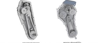
Basic design
Let's consider the device of an energy storage device. On the vast majority of modern trucks you can see brake chambers. Which are equipped with spring energy accumulators. This is a classic design, developed back in the 50s. This type of energy accumulator is considered the most reliable and durable. But the experience of using such devices in difficult conditions has revealed weaknesses - low corrosion resistance, poor protection of the mechanism from moisture and dirt, poor wear resistance of seals. All these factors do not have the best effect on the stability of the units and lead to failure of the energy storage unit.
The unit accumulates the energy of the compressed spring and, if necessary, releases it. What type of energy accumulator does the Wabco device have? Most often it is installed on the brake chambers and consists of a housing, a piston, a pusher, and a screw-axle. The spring has a fairly high power. It can release a force of about 2 tons. After this, the piston and pusher press with this force on the rod in the brake mechanism drive. When compressed air comes out from under the piston of the device (energy accumulator), holding the spring compressed, then the parking brake comes into operation. When it has worked, air again enters under the pistons.
We continue to study the design of a brake chamber with a spring energy accumulator. The screw-axis in this unit is also important. It is necessary to be able to release the brake manually. Switching off is carried out by compressing the spring. Sometimes this need for manual shutdown arises when you need to transport the machine if there is no air in the receiver due to a faulty compressor or a non-working engine.
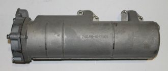
energy accumulator ZIL-KAMAZ
Trailer brake control valve
The brake chambers of the rear wheels with spring energy accumulators are designed to activate the brake mechanisms of the rear wheels when the service, parking and spare brake systems are engaged.
energy accumulator
Only a highly qualified mechanic should disassemble, inspect, clean and lubricate parts of cylinders with a spring energy accumulator in a workshop using a special device in compliance with safety measures.
Remember that a strong spring is compressed in the cylinder; if you disassemble the energy accumulator incorrectly and carelessly, you can get injured
Assembling and disassembling the brake chamber
. Place the brake chamber on a level table and, loosening the lock nut 28, but without removing it, unscrew the fork 29. Then supply air under a pressure of at least 0.5 (5 kgf/cm2) into the cavity of the spring energy accumulator. Unscrew the clamps 30 securing the drain tube 12* and remove it.
Unscrew the bolts 31 securing the clamps 32 of the camera body and carefully, holding the housing 1 with your hand, remove the clamps 32, remove the housing 1 assembled with the rod, spring, support disk and cap. Remove membrane 16
Then, compressing the spring 20, unscrew the fork lock nut and remove the support disk 17 assembled with cap 2.
energy accumulator
Release the air from the energy accumulator and secure it in a vice with soft jaws by the flange-cover 14 upwards.
On-1+, heat it with a heating device to a temperature of 200 C and unscrew it with a special socket wrench. Re-introduce air into the energy accumulator under a pressure of at least 0.5 MPa (5 kgf/cm2).
Insert a special split mandrel, model I 804.00.008, into pusher 4 and, pushing bearing 13 down with it, remove the piston.
Bleed the air from the energy accumulator. Turn the energy accumulator over in a vice at 180a and unscrew the release screw 9 with a special socket wrench (Fig. 8-1 b) (see Fig. 8-15). Then remove the energy accumulator from the vice and, turning the flange cover down, remove the s-piston 4 thrust ring 27 of the bearing, bearing 13 and ring 25.
To further disassemble the energy accumulator, it must be installed in a special device • model P 804.33.004 (Fig. 8-17) and the power spring 8 must be compressed with the screw of the device.
Then unscrew bolts 23 with a spanner wrench, holding nuts 24 with another wrench.
After this, being careful, unscrew the screw of the device, and remove cylinder 7, power spring: 8 and piston 4. energy accumulator
energy accumulator
Warning. It is strictly forbidden to unscrew bolts 23 securing the energy storage cylinder outside the device.
On the surface of the hulls. parts are not allowed to have cracks, hairlines or other defects visible to the eye. Parts must be cleaned of rust and burnt marks.
All rubber parts must be replaced with new ones.
For assembly, install the flange-cover 14 on a special device (see Fig. 8-17) and insert the piston 4 assembly into it. Next, install the power spring 8 with a tapering loop to the piston and cover it with cylinder 7 so that the drain pipe pipe is located in the middle between the bosses of the flange-cover 14.
Compress the spring 8 with the screw of the device and secure the cylinder 7 to the flange-cover with bolts 2 and nuts 24. Unscrew the screw of the device, remove the energy accumulator from it and secure it in a vice by the flange-cover 14.
tighten the brake release screw 9 with a special key, having previously lubricated it with graphite lubricant VNIINP-232, GOST 14068-79. Turn the energy accumulator over in a vice by 180 degrees, supply air to the energy accumulator under a pressure of at least 0.5 MPa (5 kgcm2) and install it in piston 4 (see Fig.
8-15) ring 25, upsetting it with a mandrel, needle bearing 13 filled with CIATIM-221 lubricant, and thrust ring 27, oriented with its chamfer upward.
energy accumulator
Release the air from the energy accumulator and unscrew the brake release screw 9, while observing whether the pusher 4 is supplied. After normal release of the brake is ensured, you need to tighten it again with a torque of 40...50 N.
https://www.youtube.com/watch?v=iPLSGQyZTX8
m Re-inject air under a pressure of 0.5 MPa into the energy accumulator, visually check the correct installation of the thrust ring 33, put the rubber sealing ring on the pusher 8, apply a drop of anaerobic sealant to its threads and screw it into the piston 4 with a torque of 40-50 Nm.
Add oil to the energy storage chamber
You will need to add about 100-150 grams of oil to the energy storage chamber. To do this, you will need to find some kind of syringe for pumping oil. We will pump oil through the drain tube.
The poured oil will lubricate the walls of the energy accumulator piston during operation, and will lubricate the piston cuff and prevent the cuff from drying out, thereby increasing its service life.
watch the video
Operating principle
Let's look at the design of the Kamaz energy accumulator in analysis. When the service brake system is activated, air compressed by the compressor enters the cavity above the diaphragm. The diaphragm bends under pressure and acts on the disc, moving the rod. The latter turns the adjusting lever, which actuates the expansion cam of the brake mechanism.
What is the structure and operation of the Kamaz energy accumulator? The rear and middle wheels are braked according to the same principle as the front wheels. When the driver uses the parking brake, the air that is under the piston of the device (energy accumulator) comes out. The spring relaxes and the piston moves to the right. Due to the diaphragm, the pusher acts on the rod, which moves the adjustment lever.
As a result of all actions, the car may slow down to a complete stop. When the driver releases the parking brake, air is again supplied under the piston. The latter moves to the left, the spring compresses, the rod returns to its normal position. This is how an energy storage device works.
Reviews say that if you need to brake the car in an emergency, when it is not possible to use emergency braking, you should unscrew the handbrake screws responsible for these tasks.
Types
These units differ from each other in their completeness, type of connection to the brake chamber, and technical characteristics.
As for the configuration, regardless of the principle of operation of the energy accumulator, there are separate devices for installation on different types of brake chambers, as well as devices together with the brake chamber.
What is their task? The first type is necessary for repair work of brake chambers, as well as modernization. The second type of component has already been selected according to technical characteristics and can be used for repairs without the need for additional assembly and disassembly.
Energy accumulators are also divided into two types based on their connection to the brake chamber. This is a flange connection with one clamp and a bolt, as well as a flange connection with two clamps.
Flanges for energy storage batteries are always used, as stated in the reviews. They allow not only to securely fix the components, but also to position them correctly relative to each other. If you use the first type of connection, then the flange is connected to the energy accumulator with bolts and nuts. And with a brake chamber - a clamp.
There is an important difference between conventional energy accumulators and mechanisms assembled with a brake chamber. This is the effective area of the membrane, piston. It is expressed in square inches. Models with an area of 20, 24, 30 square inches are now widely used.
How to replace it yourself
To reinstall the “energy”, you must follow the instructions for installing the unit step by step.
A couple of tips for assembling the device:
- the operation must be carried out without dust, metal shavings and other impurities;
- using a special lubricant for rubbing parts will prolong service life;
- During assembly, rubber gaskets and seals should be handled carefully so as not to damage them;
- It is very important to follow the installation instructions.
In some cases, it may be necessary to turn off the “energy engine”. For this:
- prepare the tool, choose comfortable clothes, since the work is carried out without removing the device, directly under the machine;
- carefully unscrew the air supply hoses and clamp them;
- insert the release bolt into the grooves, screw the nut on top until it stops.
It is better to store the brake release bolt separately, for example, in the cab of a truck. Otherwise, it may become unusable under the influence of environmental conditions.
Installation
On a truck, the brake chamber and the spring energy accumulator connected to it are mounted on the brackets of the expansion knuckles. Fastening is carried out with two nuts screwed onto the chamber bolts. The installation area must provide sufficient space to connect hoses and piping for compressed air supply. In general, installing an energy storage device is a relatively simple process.
First, you need to dismantle the brake chambers and connect them to energy accumulators. Hoses for air in the cavity above the diaphragm are connected to the corresponding fittings. Next, install and power the receiver. It supplies air to the accelerator valve and the parking brake lever. Next, the tube goes to the accelerator valve in the upper part.
Then you just need to supply air to the top of the energy accumulator - where the springs are installed. If you need to replace the energy battery, you can use this brief instruction.
Assembly Recommendations
Specialists in truck brake systems provide recommendations for assembling these units. First of all, assembly must be carried out very carefully - no chips or abrasive dust, dirt or other substances should get inside the mechanism. You also need to remember what is written on the flange - the spring is under tension.
During assembly, all parts of the mechanism that rub must be lubricated with a thin layer. When assembling rubber elements, it is important to exercise maximum caution - they are very easy to damage.
If rubber products have defects, the element must be replaced. Connecting the camera must be carried out strictly according to the instructions to the car. The release screw must be fully tightened. After assembly and installation, you need to supply and bleed air into the system at least three times.
The same recommendations should be followed when dismantling the unit. How to remove the energy accumulator on a MAZ car? The device is dismantled in the reverse order. You need to remove the brake chamber and then unscrew the flange connection nuts.
Malfunctions and repairs
Malfunctions of "energy units".
During the operation of “energy engines” on semi-trailers and trailers, problems often arise for the following reasons:
- high humidity and dirt enter the structure, adversely affecting its working parts;
- corrosion that occurs under the influence of the environment harms the parts of the mechanism;
- sealing elements have low wear resistance and quickly become unusable.
As a result of the combination of processes, the functionality of the semi-trailer braking system is impaired. The structure needs to be repaired or replaced.
In this case, you need to contact a specialized service or do the work yourself.
Selecting units
The market for spare parts for trucks offers quite a large selection. You can select devices with different parameters, units for trailers with SAF, ROR, BPW axles. There is also a large selection of energy accumulators for semi-trailers with disc and drum brakes. The energy accumulator and brake chambers can be installed both on imported models and on domestic KamAZ and MAZ vehicles, although this is not always worth doing, reviews say. The car must be equipped only with spare parts intended for a specific model. Otherwise, the high-quality and stable operation of such a mechanism cannot be guaranteed.