Design
Unlike front-wheel drive foreign cars, on all-wheel drive UAZ Patriot vehicles the clutch slave cylinder (its adjustment is at the end of the article) is hydraulic and is controlled using fluid pressure, and not a cable. The design of this element includes several components. This:
- Frame. It is made of plastic or metal.
- Piston (working rod).
- A valve that releases air when the clutch system is bleeding (adjusting).
- Retaining ring.
- O-rings. Made from durable rubber.
- Return spring.
- Pusher. It affects the previous element.
Device
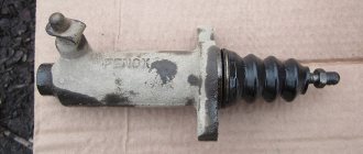
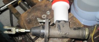
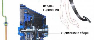
The clutch slave cylinder (CLC) is a hydraulic cylinder that receives the force created in the line by the clutch master cylinder and transmits it directly to the fork, which acts on the release bearing.
The slave cylinder is mounted on the clutch housing.
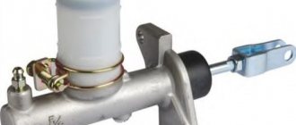
The cylinder consists of a body, a piston 4 with a rubber cuff 5, a pusher 8, a bypass valve 9 with a rubber cap 10. The pusher 8 can be adjusted in length using a screw-in part, its outlet from the body is sealed with a protective cover 6. Valve 9 is designed to remove air from systems.
Clutch release slave cylinder: 1 – hose; 2 – piston spring; 3 – cylinder body; 4 – piston; 5 – sealing cuff; 6 – protective cap; 7 – retaining ring; 8 – piston pusher; 9 – bypass valve; 10 – protective cap
Signs of trouble
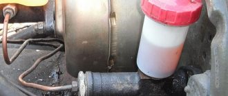
How do you know if your car needs to replace the clutch slave cylinder? UAZ is a very reliable car, but this part can also fail. A breakdown can be determined by several signs. Firstly, this is a sharp decrease in the liquid level in the tank. If there is a leak, the cylinder boot may have broken through. Damage may also affect rubber or aluminum tubes. Check their integrity. Secondly, the pedal stroke becomes softer. “Clutch failures” are observed. This indicates the presence of air in the system.
DIY replacement
First you need to drain the remaining liquid in the system. This can be done using a syringe. This operation is necessary to flush out dirt from the hydraulic drive system. On some models, access may be blocked by the cooling system expansion tank. For convenience, remove the container’s fastening nuts and remove the hose. It should be unscrewed with a 10mm wrench. Next, we dismantle the metal tube that comes from the clutch master cylinder. It can be copper or aluminum. After this, we remove the main cylinder, having previously unscrewed the two fastening nuts with a 13mm wrench. Using a 17 socket, you need to remove the hose that comes from the working cylinder. Next we will need the key for 13 again.
DIY repair
So, the part has been removed and is ready for disassembly. First, unscrew the air bleed valve and remove the retaining ring. After disassembling the part, we inspect the condition of all elements - spring, piston, pusher and sealing rubber bands. They must not show any signs of mechanical damage. Next, we wash the insides of the element. There is no need to do this with aggressive liquids like gasoline and diesel fuel. Fill a medical syringe with hydraulic fluid and use pressure to clean out the dirt inside it.
Repair
If the clutch pedal fails, in order to avoid unreasonable disassembly of the cylinder, it is worth initially bleeding the system and expelling any air that could get in when the fluid in the tank drops below the minimum permissible level. If this does not help, you should start repairing. For this case, a clutch slave cylinder repair kit is available for sale.
Disassembling the RCS
1. Remove the rubber protective cap 6 from the working cylinder and take out the pusher 8 along with the cap. 2. Remove the cap from the pusher. 3. Remove the lock ring 7. 4. Remove the piston 4 with the sealing lip 5 and the spring 2 from the cylinder body. To avoid damage to the piston and seal, apply compressed air to the hose opening. 5. Remove the sealing collar 5 from the piston. 6. Unscrew the bypass valve 9 and remove the protective cap from the valve. Wash the hydraulic drive parts thoroughly in brake fluid or alcohol, blow with compressed air and inspect.
When repairing the clutch slave cylinder, you need to follow some tips : - when repairing the cylinder, you don’t have to completely remove the fluid from the hydraulic drive (it’s enough to pinch the hose); — it is not recommended in kerosene, diesel fuel or gasoline, after which the cuffs and other rubber products may swell; the best option for washing is brake fluid; — Before assembly, you must lubricate all parts with brake fluid.
When should you not restore?
In some cases, repairs will not work. The working cylinder is replaced if the housing is damaged (cracks) or there is a large hole inside it. The latter may occur due to a faulty or defective rod. In case of any of these malfunctions, the UAZ clutch slave cylinder is replaced entirely with a new one. The cost of the element is about five hundred to six hundred rubles. The clutch master cylinder costs a little more - 750 rubles. The repair kit can be purchased at a price of 150 to 200 rubles. The amount is not impressive, so if you have limited time, it is better to immediately replace the element with a new assembly. After the clutch slave cylinder is installed, the UAZ needs to be “pumped”. This way we will eliminate all existing air pockets in the lines and adjust the normal pedal travel.
Leveling up
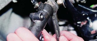
After successful installation and assembly of the element, it is necessary to fill in new hydraulic fluid. The same one is used as for the brake system. After this, unscrew the air valve of the working cylinder several turns and press the clutch pedal 5-7 times. To avoid running to the salon several times, call an assistant who will bleed the system. Be careful - when you press the pedal, hydraulic fluid will flow out of the valve. Therefore, prepare the container first. This could be an ordinary mineral water bottle.
Hydraulic clutch release
Hydraulic clutch release for utility vehicles: 1 - cover; 2 — pedal axis; 3 - fork; 4 and 12 — tension springs; 5 — clutch release pedal; 6 - coupling; 7 - spring; 8 — ball joint; 9 — clutch release fork; 10 - hydraulic hose; 11 - working cylinder; 13 and 18 — caps; 14 — bleeding valve; 15 — cuff; 16 - piston; 17 — pusher; 79 — lock nut; 20 — screw part of the pusher; 21 — master cylinder pusher; 22 — protective cap; 23 — outer cuff; 24 - piston; 25 — return spring; 26 - fitting; 27 — inner cuff; 28 — washer; 29 — compensation hole; 30 - bypass hole; 31 — clutch master cylinder; 32 — hydraulic tube; 33 - tank; 34 - mesh filter
The clutch release drive is hydraulic. The drive consists of a suspended pedal, a master cylinder, a pipeline and a working cylinder. On wagon-type cars, the fuel tank is located under the instrument panel to improve access to it, and the instrument panel has an easily removable cover. On utility vehicles, the reservoir is installed directly on the master cylinder body. When you press the clutch pedal, the piston moves and the compensation hole 29 closes (see Fig. 83), after which the working fluid is forced out of the master cylinder and moves the piston and pusher of the working cylinder, transmitting the force from the pedal to the clutch release fork. When the clutch pedal is smoothly released, the pressure in the system drops and the displaced fluid returns to the master cylinder. When the pedal is abruptly released, the liquid forced out of the system into the main cylinder does not have time to fill the space vacated by the piston and a vacuum is created in the main cylinder in front of the piston head. Under its action, the liquid from the nutrient tank passes through the bypass hole in the piston head into the cavity in front of the piston head, pushing back the spring plate and compressing the edges of the sealing collar. Subsequently, this excess liquid is forced out through the compensation hole back into the nutrient tank. The spring constantly presses the piston to its rearmost position until it hits the washer.
There is a constant gap of 0.3...0.9 mm between the pusher head and the spherical cavity on the piston, which ensures guaranteed free play of the clutch pedal. The full travel “B” of the pedal, which ensures disengagement of the clutch, is 200 mm. For normal operation of the clutch, it is required that the gap between the bolt heads of the clutch release levers and the bearing be within 2.5...3.5 mm. This corresponds to a stroke of the outer end of the clutch release fork of 3.5…5.0 mm and a free stroke “A” of the clutch pedal within the range of 35…55 mm, measured along the pedal platform. The free play of the pedals is adjusted by changing the length of the working cylinder pusher.
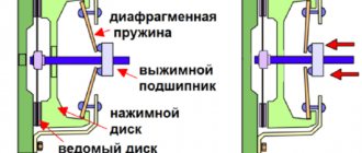
The principle of operation of the clutch on the UAZ loaf
By pressing the pedal, the driver acts on the fluid in the line. The fluid transfers pressure from the master cylinder piston to the slave cylinder piston. The master cylinder moves the fork piston.
The release fork presses against the release bearing, which transmits force to the clutch mechanism, which disengages the transmission from the transmission.
By releasing the pedal, the driver returns the entire mechanism to its original state. Under the action of the return spring, all elements involved in the process of disengaging the clutch assume their normal positions, this is how the UAZ loaf clutch works
Operation of the GVC
Below is a brief description of how the clutch works:
- When you press the clutch pedal, the pusher moves the piston and the compensation hole closes.
- It pushes fluid in front of it into the system, creating pressure.
- This pressure acts on the piston of the working cylinder, which pushes the rocker arm through the rod.
- The fork, moving the release bearing, acts on the crankcase petals, releasing the pressure plate from the clutch disc.
The valve and disc play an important role in the pumping process. Even if the system is not primed, it will still fill up. Simply unscrew the master cylinder valve and allow the fluid to flow through it. It fills the system by gravity, the same applies to the brakes.
The liquid enters through the expansion port into the cavity in front of the piston through the valve into the line. When filling is complete, the liquid flows out through the valve. The most important thing is that the piston rod should not be extended, and the expansion hole should not be blocked by the handle.
When pumping, everything happens a little differently.
- When the piston moves forward, valve 19 is open.
- When moving backwards, the valve is closed and the front valve creates a vacuum.
- There are holes in the piston that are closed by plate 3. It retracts and opens the holes. Liquid flows from the space above the piston and reservoir through the bypass hole into the space in front of the piston, which is under pressure. The collar (cork) allows it to overflow.
- When the lock ring is reached, the piston stops and the spring compresses the plunger and plate. It's ready for a new cycle.
Clutch design of the most common UAZ models
The entire clutch system UAZ loaf
First, let's define the term "clutch". It is necessary for smooth connection and disconnection of the crankshaft with the vehicle transmission. This is necessary when changing the driving mode (changing gears in the transmission) or stopping the car. The UAZ 469 military jeep was equipped with a dry single-plate clutch, a very popular system in the automotive world at that time. This coupling consisted of the following components:
- pressure disk in the housing;
- special pressure springs and clutch release levers;
- friction disc equipped with friction linings.
The general design looks like this. The so-called casing (clutch housing with all mechanisms) is bolted to the crankshaft. Alignment is established according to the factory marks on the housings. It is important to understand that when the driven and driven plates touch, a tremendous amount of friction is created to transfer torque from the crankshaft to the vehicle's transmission, which transfers it to the wheels.
Driven clutch disc
Driven clutch disc
- friction linings;
- rivets;
- driven disk spring;
- damper plate;
- damper spring;
- hub;
- friction rings;
- adjusting rings;
- driven disk;
- persistent finger;
- balancing weight;
The driven clutch disc has two friction linings 1, riveted to the disc independently of one another through leaf springs 3, and is connected to the damper plate 4 using pins 10. Cylindrical damper springs are located simultaneously in the windows of the hub flange, driven disk and damper plate. When transmitting torque from the friction linings to the hub, the springs are compressed and ensure smooth transmission of torque from the engine to the transmission. The rotation of the friction linings with discs relative to the hub is limited by the pins resting on the edges of the U-shaped cutouts made in the hub flange. The friction vibration damper of the driven disk consists of two friction washers installed on both sides of the hub flange and adjusting rings. The outer diameter of the friction lining of the driven disk is 254 mm, the inner diameter is 150 mm, and the thickness of the lining is 3.5 mm. The dimension of the hub splines is 5.4 x 28.5 x 35, the number of splines is 10. The clutch is engaged using a fork mounted on the clutch housing, which moves the clutch with a thrust ball bearing. The bearing presses on the heads of the adjusting screws of the clutch release levers. The levers, turning on the axles, retract the pressure plate and disengage the clutch. After removing the force from the fork, the release springs retract the clutch with the bearing to its original position. The characteristics of the release springs are given in the table.
| Spring catalog number | Name | Loaded spring length, mm | Spring load, N |
| M-2472 | Pedal release spring | 160 | 140…160 |
| 11-7547 | Same thing, forks | 150 | 75…95 |
| 11-7562 | Same thing, couplings | 36 | 27.5 |
Clutch malfunction UAZ loaf
The main malfunction of the GTZ is damaged flanges. If the “mushroom” is faulty, the piston will not create pressure in the system, and the UAZ loaf clutch will stop compressing. It usually has nicks, cracks, or is simply worn out. Frequent, repeated clicks will, of course, help, but not for long. You can't rush and get stuck. You need to replace the cuff or replace the main cuff entirely.
In the second option, if the second ring is damaged, the liquid will leak out. DOT will drip onto the cabin floor. It is quite possible to replace the ring from the repair kit.
Frequent malfunctions and their causes
The clutch system of a UAZ car is characterized by various violations: the reinforced clutch of the UAZ is a loaf, the mechanism does not squeeze out, slips or does not pump. Timely maintenance, replacement of worn parts, lubrication and monitoring of the fluid level in the tank, diagnostics of all systems and mechanism components allows you to avoid such problems.
Clutch repair UAZ loaf
Having a diagram of the internal structure allows you to carry out repairs yourself in case of simple defects. Increased fuel and oil consumption, coolant leakage, unusual noises and knocking in the mechanism are the first signs of the need for repairs. Maintenance and replacement of worn parts help extend the life of parts and vehicles.
How to adjust the clutch pads
To adjust the UAZ loaf clutch, the following repair work must be performed:
- Using a ruler, measure the free radius of movement of the drive pedal that disables the mechanism. The standard value for the spring type should be in the range from 35 to 55 mm, for the membrane type - from 5 to 30 mm.
- Measuring the full travel of the pedal when it is lowered all the way. The standard value for the lever-spring type is 18.5 cm, for the membrane type - 16.5 cm.
- Set the desired position by changing it using the key.
- Check the distance with the pedal down between the engine block bulkhead and the center of the rod shaft. The value of 9.6 cm must be achieved. The fork free play must be at least 1.7 cm. Changing the length of the work basket bias rod is an adjustment tool. To do this, remove and reinsert the pusher until the desired value is reached.
How does a clutch slave cylinder work?
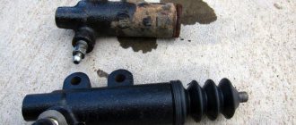
The liquid flowing through hose 1 into cylinder body 3 presses on piston 4. The piston acts on pusher 8, which in turn, through the clutch release fork, presses on the release bearing.
The pedal stroke at which the clearance in the clutch drive is selected is called free play. The pedal stroke after selecting the gap to the stop is the working stroke. Free and working travel form the full travel of the clutch pedal.
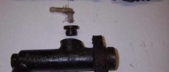
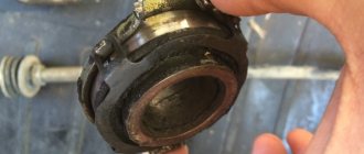
Clutch slave cylinder
Clutch slave cylinder
Replacing the clutch of a UAZ loaf with your own hands
First, drain any remaining fluid in the system. This can be done using a syringe. This operation is necessary in order to flush the hydraulic cylinder system from contaminants. On some models, access may be limited by the cooling system expansion tank. For convenience, loosen the nuts holding the tank and remove the hose. It should be unscrewed with a 10 mm wrench. Next, remove the metal tube coming from the clutch master cylinder. It could be copper or aluminum. Then remove the master cylinder by unscrewing the two mounting nuts with a 13mm wrench. You must use a 17mm socket to remove the hose coming out of the slave cylinder. Then we will need a 13mm wrench again.
Use it to unscrew the two bolts securing the clutch cylinder. The UAZ is in neutral gear at this time. The working cylinder itself in this car is installed on the gearbox housing. Carefully remove the pushrod from the fork to avoid damaging other components. If the hoses are removed “on the fly”. (i.e. with the component removed), the cylinder can be secured on one side with an adjustable wrench, and the tube can be unscrewed on the other side using a spanner. However, be careful, as the rubber may break under mechanical stress.
Need for adjustment
Adjusting the pitch of the cone in the clutch cylinder is done to ensure that the clutch performs its task correctly. If configured incorrectly, two types of interference may occur.
Free play adjustment
This is the distance the pedal can be moved without encountering resistance and without causing the clutch to engage or disengage. The free wheel is adjusted after replacing the mechanism or when the discs are worn. The clutch release drive consists of a working drive and a release bearing fork. The release mechanism housing is located on the bell body and is secured with two bolts. The pusher and rocker arm are located inside the housing.
The free wheel is adjusted by changing the length of the rod with the cylinder removed.
To adjust, follow these steps:
- Dismantle the clutch cylinder and remove the pusher;
- Loosen the lock nut and unscrew (tighten) the piston rod no more than 5 mm;
- Reinstall the pusher and assemble the control center.
Since the adjustment unit is not visible from the outside, if the adjustment is incorrect, the slave cylinder must be disassembled again.