Instructions for using the mechanism for attaching agricultural implements
The hitch mechanism is used to attach mounted and semi-mounted agricultural implements to the MTZ-82/80 tractor.
The mechanism structure is shown in Fig. 72.
The forks of the braces are connected by bolts to longitudinal rods 10. The forks have slots. When operating the tractor with wide-cut implements, install the fork on the slot. This will ensure better adaptability of the implement’s organs to the soil topography along the working width.
The design of the right brace 8 provides for its length adjustment using handle 7.
To decrease the length of the brace, the handle should be rotated counterclockwise, to increase it - clockwise.
Do not adjust the left brace when working with mounted implements; its length must be constant and equal to 515 mm. To level the plow in the transverse plane, adjust the right brace.
Leveling the depth of travel of the front and rear working parts of the mounted implement is ensured by adjusting the length of the central link. Adjustment is carried out by rotating the pipe using a handle.
Make sure that the lock nuts of the brace, limit chains and central link are securely tightened: loosening the lock nuts can lead to disruption of the adjustment of the linkage mechanism and to thread breakage.
When moving a tractor with an implement over long distances, the central link must be shortened to improve the cross-country ability of the unit.
Restrictive chains are used to limit the lateral movements of implements. The chains are attached at one end to the longitudinal rods, and at the other to brackets installed on the axis of the longitudinal rods. Adjusting bolts are screwed into the brackets, which, resting against the housing of the rear axle of the tractor, provide tension on the chains when lifting the implements into the transport position to reduce their swinging in the transverse plane.
Bolt adjustment
Adjust bolts 12 (Fig. 72) in the following order:
1. Attach the implement to the hinges of the longitudinal and central links. Screw the adjusting bolts into the brackets until they are tight.
2. Raise the implement so that its working parts do not touch the ground.
3. Adjust the length of the limit chains by rotating the ties so as to ensure freedom of rolling of the trailing link joints in accordance with the implement’s operating manual. For mounted plows, the freedom of rolling in the horizontal plane should be 120 mm in each direction from the average position.
4. Adjust the length of the right brace to the specified working depth (when working with plows).
5. Raise the implement to the transport position, unscrewing the bolts from the brackets, tighten the chains so that they sag slightly, ensuring that the implement swings no more than 20 mm in both directions.
6. Securely secure the bolts with locknuts. Each change in the length of the right brace must be accompanied by an adjustment of the right bracket bolt to ensure self-locking of the limit chains.
When inter-row cultivation, sowing, and also when working with a towed device, the longitudinal rods of the hitch mechanism must be completely blocked from lateral movements in order to avoid damage to plants or rocking of the trailer. Blocking is carried out by shortening the length of the chains as much as possible within the limits of the existing adjustment; in this case, the adjusting bolts must be screwed into the bracket all the way.
Violation of this order may lead to breakage of limiting circuits or other damage.
- Back
- Forward
Automatic hitch SA 1 (Triangle)
A device for automatically attaching machines on MTZ 80(82) “Automatic coupler SA 1” (the so-called “triangle”), is attached by three points to the hitch - two hinges of the ends of the lower longitudinal bars and the central link. The contact connecting part of CA 1 is made of a metal profile in the shape of a triangle. Fixation is carried out with a spring lock with a latch. When hanging, the triangle fits its profile into the internal profile of the triangle of the machine being hung. With the upper guide angle 8, the device, when connected, aligns the hole of the outer triangle with the spring-loaded latch 4 of the triangle on the tractor. If a match is made, the latch closes automatically under the action of a spring. To disconnect the mounted device, press down the lock lever 9 and disengage the triangle 3 by lowering the linkage. The drive of the control lever for the coupling device lock is brought out using a cable 10 to the driver's seat to ensure operation without outside help.
The CA 1 device is universal and is used in mounted systems of tractors of different brands.
The MTZ 82(80) hitch has a similar design to all wheeled tractors of the MTZ family and universal row-crop machines of the YuMZ-6, T-40, T-25 brands. Additionally, the hitch of modern tractors can be equipped with a lift-type towing device, as well as towing devices of various designs. Crawler tractors are equipped with a reinforced hitch with the possibility of two or three point connection of the hitch to the tractor.
Read also: How much does a AA battery weigh?
Rear linkage of the MTZ-80, MTZ-82 tractor device.
The attachment (hitch mechanism) is used to connect mounted, semi-mounted and trailed agricultural machines to the tractor, adjust the working position, lift into the transport position and lower into the working position of mounted and semi-mounted machines. The three points of the hitch mechanism—the two lower link pivots and the upper link pivot—are typically attached to an automatic hitch (see Figure 3), which then engages the lock on the machine. However, there are still many agricultural machines on farms that are not equipped with an automatic coupling lock. Such machines are attached directly to the hinges of the linkage linkages.
The power cylinder of the linkage mechanism is connected to the rear axle housing through a bracket. The bracket is secured to the rear axle with four special hardened bolts and two hollow pins. Using bending plates, the bolts are protected from self-loosening. The cylinder rod fork is connected to a rotary lever 14 (Fig. 1), mounted on the splines of the shaft 13, rotating in the bushings of the bracket 12. At the ends of the shaft 13, external levers 11 and 16 are installed in the same way. Using braces, they are connected to the lower rods 4 and 28.
Rice. 1 Attachment: 1 and 26 - rear ends of rods; 2 - eye; 3 and 9 - couplers; 4 — left thrust; 28 — right thrust; 5 - bottom screw; 6 — tie rod; 7 — axis of lower links; 8 - bolt; 10 - top screw; 11- left linkage lever; 16 — right linkage lever; 12 — bracket; 13 - rotary shaft; 14 — cylinder lever; 15 — upper link mounting bracket; 17 — right brace; 18 — roller; 19 — driven gear; 20 - drive gear; 21 — handle; 22 - pipe coupler; 23 — fork screw; 24 — top link; 25 — handle; 27 — tie screw; 29 — power sensor bolt; 30 — sensor earring; 31 - finger; 32 — cross member; 33 — king pin; 34 - fork; 35 - finger.
The transmission of motion from the cylinder to the mounted machine is transmitted as follows: cylinder rod - rotary lever - shaft - outer levers - braces - lower links - machine, which is also connected to the upper (central) link. When raising and lowering the hitch mechanism, the agricultural machine moves along a trajectory determined by the movement of the rear ends of the lower and upper links. The brace on the left side of the tractor is usually not adjustable, and the size between its lower and upper pins should be 500 mm. This brace consists of two screws - 5 and 10 and a tie 9. The length of the right brace is adjusted by the handle 21 of the roller 18, on which the drive gear 20 is attached, transmitting rotation to the gear 19. This gear is rigidly connected to the tie-pipe 28, into the thread of which they screw or turn out the fork screw 23. Rotating the handle 21 of the roller 18 clockwise, when viewed from above, increases the length of the brace; by rotating in the opposite direction, it decreases it.
The upper link 24 is connected to the earring 30 of the force regulation sensor. The front hinges of the lower links are fixed to axle 7, passing through steel bushings pressed into the eyes of the rear axle. Brackets 6 are fixed on the same axis, connected using screws 27 and couplers 3 with the lower rods. They constitute limit chains and provide adjustment of the lateral movements of the machine in transport and working positions. Bolts 8 are screwed into the brackets 6, which, resting against the rear axle housing, provide tension on the chains in the transport position of the machine and reduce its swaying. A force regulation sensor is mounted in bracket 12 of the rotary shaft.
To improve the adaptability of wide-grip agricultural machines to field unevenness and the ability to move them in a vertical transverse plane relative to the tractor frame, the braces to the lower links 4 (see Fig. 1) and 28 should be connected through grooves in the forks (see position A). In this case, the forks of the braces must be attached to the rods with the holes forward, so that the pins connecting the rear ends of the rods with the front ones do not interfere with the movement of the braces along the grooves.
When working with heavy attachments (for example, seeders), it may be necessary to increase the lifting capacity of the attachment. This is achieved by connecting the braces to the longitudinal rods through additional holes located closer to the rear hinges. In this case, the forks of the braces must be positioned with the grooves forward so that they do not affect the pins connecting the ends of the longitudinal rods.
To attach trailed machines to the tractor, a crossbar 32 with a fork 34 is mounted on the lower links 4 and 28.
Before installing the cross member, it is necessary to remove the rear ends 1 and 26 of the lower links, for which you should unpin and remove the pin connecting the front and rear ends of the links with eye 2. The cheeks of the cross member are inserted into the grooves of the front ends of the lower links, which are secured with fingers and eyes.
To avoid lateral movements of the towing device, it is necessary to shorten the length of the limiting chains as much as possible by rotating the tie rods 3. Adjusting bolts 8 should be completely screwed into brackets 6.
Mechanism for fixing mounted machines. The increased transport speeds of the tractor and the weight of mounted agricultural machines required the creation of devices to reliably hold them in the transport position.
The mechanism for fixing mounted machines serves this purpose.
Rice. 2. Fixation mechanism: 1 - handle; 2 — bracket guide; 3 — bracket visor; 4 - bracket; 5 — lever tooth; 6 and 7 - cheeks; 8 — cylinder bracket; 9 — cylinder axis; cylinder; 11, 13, 19 and 21 - levers; 12 and 14 - axles; 15 — bracket; 16 - spring; 17 and 20 - thrust; 18 - power lever.
In the transport position, the mechanism connects bracket 8 (Fig. 2) of cylinder 10 with the rotary lever 18 of the attachment. It eliminates the possibility of spontaneous gradual lowering of the machine due to oil flowing through the gaps in hydraulic units (in the cylinder, distributor, regulator, hydraulic booster), as well as its fall due to rupture of pipelines or high-pressure hoses, or accidental transfer of the distributor or regulator handle to the “forced lowering” position "
Read also: What paint goes on wood varnish
The fixing mechanism is a bracket 4, connected by means of two cheeks - 6 and 7 with the axis 9 of fastening the hydraulic cylinder 10 to the bracket 8. The power lever 18 has a tooth 5, with which the bracket comes into contact when the mechanism is in a fixed position. In this way, lever 18 is connected to axis 9 and the hydraulic system (cylinder, oil lines, distributor) is completely unloaded.
In the upper unfixed position, the mechanism is held using a locking device consisting of levers 11 and 13 connected by an axis 12, a bracket 15 and a spring 16. The locking device is controlled by the driver with handle 1 through the open rear window of the cabin using rods 17 and 20, levers 19 and 21 .
The bracket 4 has a visor 3 with a sliding surface for interaction with the outer surface of the tooth 5 of the power lever 18 and a guide 2 for interaction with the cylinder rod fork 10.
Blocking the attachment with the machine attached to it in the transport position occurs as follows. When the hydraulic cylinder rod is retracted all the way, the attachment rises to the transport position. In this case, the power lever 18 approaches the hydraulic cylinder body and stops in a position in which its tooth 5 is under the supporting surface of the bracket 4. When you press handle 1, the levers 19 and 21 will move the rod 17, which, overcoming the force of the spring 16, will deploy the lower lever 13 clockwise relative to axis 14. The upper lever 11 will rotate counterclockwise and release the bracket 4 onto the power lever 18. When the pressure in the hydraulic cylinder is removed (setting the distributor spool to the “floating” position), the attachment will lower slightly under the influence of gravity of the attached agricultural machine down until the working surface of the tooth 5 of the lever 18 is pressed tightly against the supporting surface of the bracket 4. The attachment will be blocked in the transport position.
To lower the attachment from the upper to the lower position, it is necessary to retract the hydraulic cylinder rod by moving the distributor handle to the “lift” position and lift the bracket up until it is installed on the locking device, for which you need to lift handle 1 up. In this case, levers 11 and 13, rotating around axis 12, will be installed in one line and raise the locking mechanism. After installing both levers in one line, under the influence of the spring 16, they will rotate around the axis 12 at a small angle (pass through the “dead” position) until the lower lever 13 stops in the protrusion of the upper lever 11. From the lower (open) position, the locking mechanism cannot lower spontaneously down, since the gravity of the mechanism presses the protrusion of the lever 11 to the body of the lever 13, preventing the levers from turning in the opposite direction. The attachment is unlocked and can now go down, since the lever 18 passes freely under the raised bracket 4.
If the tractor driver lowers the locking mechanism before the end of the full retraction stroke of the cylinder, guide 2 of the bracket will lie on the rod fork or visor 3 of the bracket and come into contact with the outer surface of tooth 5 of the lever, preventing the locking mechanism from lowering. When the hydraulic cylinder rod is retracted, the guide will slide along the rod fork, and the bracket visor will slide along the outer surface of the lever tooth, preventing the mechanism from lowering and thus eliminating damage to the cylinder parts (in particular, the stop of the hydromechanical valve). Only in the extreme retracted position of the cylinder rod will the bracket be able to lower onto the lever body and block the attachment.
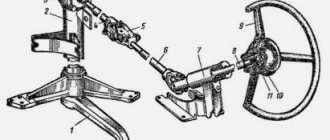
Automatic coupling SA-1. In recent years, tractors have been equipped with an automatic coupling SA-1 (Fig. 3), which greatly facilitates the connection of the tractor with machines that have so-called mating locks.
Rice. 3. Automatic coupling SA-1 (I) with a mating lock (II) of an agricultural machine: 1 - frame; 2 - cheek; 3 and 4—fingers; 5 - cable; 6 — handle; 7 — clamp; 8 - spring.
The automatic coupler is attached to the hinges of the lower and upper links of the tractor hitch. Typically, the longitudinal rods are connected to the outer fingers 4 of the frame 1. However, in cases where widely spaced lower rods interfere with work, it is recommended to use the inner fingers 3 (cultivation of tall crops).
The central (upper) link is attached through the holes to the cheek 2. To facilitate coupling, it is recommended to slightly lengthen the central link, and after attaching the agricultural machine, shorten it.
Connect the tractor to the machine as follows. The automatic coupler is lowered down using the linkage mechanism. The tractor is moved back, inserting automatic coupler I into lock II of the machine. When lifting the linkage mechanism, the automatic coupler automatically engages with the lock, the latch 7, under the action of the spring 8, enters the groove of the lock and secures the connection.
To disconnect the machine, you need to use cable 5 to turn handle 6 and remove the latch from engagement with the lock stop. While holding the cable in this position, it is necessary to lower the hitch in the “floating” position of the distributor until it comes out of the lock and drive away from the car. If the automatic coupler does not come out of the lock, you should lower the hitch while holding the distributor handle in the “forced lowering” position. However, in this case, it is necessary to ensure that there is no mutual distortion of the automatic coupler and the lock and that the tractor is not mounted on the agricultural machine.
The use of the SA-1 hitch reduces the time for connecting and disconnecting the tractor with the machine several times, facilitates working conditions, and increases work safety. [MTZ-80 and MTZ-82 tractors. 1984]
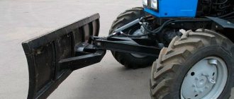
The hitch in MTZ 82 is used for using additional attachments on the tractor base. With the help of such a mechanism, a blade, a boom with an excavator bucket, as well as various mowers, cranes, and plows are installed on the machine. This allows you to use the tractor to solve most production tasks on a farm or small private farm.
This type of device is mounted on the front or rear of the tractor body. In addition, it is possible to use both options simultaneously. The simple design of the hinge ensures easy installation and dismantling of additional units.
Necessary equipment for the MTZ 82 tractor
Heated mirrors: benefits, design and installation yourself
The fastening of a specific element is carried out on the frame or chassis by a technician in combination with a control system. But there are models that are designed to work with their own chassis. If it is possible to install mechanisms for the rear and front use of mounted devices, then it is possible to expand the capabilities of innovative tractor models, regardless of their company and manufacturer. What MTZ model range exists is indicated in this article.
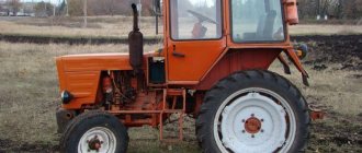
Characteristics of the MTZ 82 tractor.
Cultivators, plows, brushes, loaders and much more are installed on tractors of a given model. When a farmer needs to perform a certain number of agricultural activities, it is enough to simply equip his equipment with a certain type of attachment.
The price of a segment mower and other data are indicated in the article.
Mounting drill
This installation is made of high-quality steel, thanks to which the design can be used for drilling holes of various sizes and on any soil. The drill is installed on a three-point rear linkage.
Excavator
This device is capable of solving any given problem. But it is advisable to use it in small areas. Read about the rotary mower for the MTZ 83 tractor here.
Tank, jaw type buckets
This technique is used throughout the year. In addition to sowing activities, it can be used for watering crops and caring for the garden.
It is used both for gardening and for sowing grain.
Branch chopper
This device is also attached to the MTZ 82 tractor. Attachments are used in forestry. This need for this technology is due to the fact that the woodworking industry does not stand still. A device such as a chopper is used to chop branches and various types of wood.
The price of MTZ 80 and other features are indicated in the article.
Thanks to this, there is no need to use manual labor.
Mounted bucket equipped with backhoe
This device finds its application in the field of construction. Without it today it is difficult to imagine building a house or any other complex structure. Thanks to this work, all assigned tasks will be completed quickly and easily.
Photos of New Holland and other data can be found in the article.
Cleaning equipment: brushes, knives, etc.
Snow blowers, bulldozer blade, brushes, sand spreaders. This type of equipment is actively used in municipal services when performing certain cleaning work.
Hiller
This device is used when preparing soil for sowing. Thanks to the presence of wings, it is possible to easily and quickly cultivate the soil and make furrows. After the work has been done, all that remains is to place the seeds in the grooves and sprinkle with soil. The soil can be prepared using a disc or petal hiller.
Seeders
The presented devices for the MTZ 82 tractor allow you to sow planting material in the form of seeds efficiently and quickly. They arrive through bunkers at a specific distance from each other. Thanks to this, it is possible to achieve harmony in the rows of crops planted nearby. You can learn how to use Buhler for its intended purpose in this article.
Seeders are designed for sowing agricultural crops.
Lugs
When working with a tractor, it becomes necessary to create an adhesion to the surface. For these purposes, lugs are used. They increase the traction force of the tractor during plowing, hilling and collecting root crops. Today you can purchase these products in any size or type.
Description and characteristics
The MTZ 82 linkage cylinder is the most important component of the design of the working mechanism; it is used to hold it in a certain position, raise, lower, and perform various tasks. A similar element is used for the correct operation of attachments, as well as trailed devices. This kind of element has the identification number ts-100x200-3, which makes it easy to find it in the spare parts catalog. Among the characteristics of such a product it is worth noting:
- weight - 22 kg;
- nominal/maximum pressure - 16/20 MPa;
- working cylinder diameter - 10 cm;
- piston stroke - 20 cm;
- rod - 4 cm;
- nominal/maximum operating speed - 0.15-1 m/s.
It should be mentioned that a cylindrical element of this type has a wide range of applications; it is used in popular models of tractors MTZ 50, 80, 82, as well as YuMZ-6, which makes the components interchangeable. The hydraulic cylinder model is of the piston type and has a two-way operating principle. Moreover, it is made according to an outdated model, which is currently practically not used in new technology. It is called the main one because it is used to perform most tasks.
In addition to the above-mentioned cylinder, the design of the product contains 2 more similar elements with a diameter of 7.5 cm. This kind of product is called remote, since they are mounted on the body of the unit, and communication with the main hydraulic system is carried out through special pipelines and hoses.
Device
It should be noted that all cylinders installed in the tractor design are completely identical to each other in their operating principle and technical design, and their main difference is the size of the parts. When studying the structure of the main hydraulic cylinder, it is advisable to highlight several key elements of its design. Among them:
- frame;
- back and front covers;
- rod cavity and fork;
- oil line;
- piston and rod;
- MTZ 82 hydraulic cylinder mounting bracket, studs and valves.
The internal structure of the product deserves a more detailed consideration. The body appears to be a special pipe, the inside of which has been processed. It is sealed by means of rings, which are located in the corresponding cavities of the back and front covers. The studs provided by the design are used to securely connect such elements to the body, and a fork is located at the end of the back cover. It is important to remember that the cylinders with a diameter of 7.5 cm use cast iron as the material for the cover, while the main hydraulic cylinder uses high-strength steel. The oil required for the operation of the mechanism enters through the corresponding hole located in the front cover. The cylinder of the MTZ tractor is constructed in such a way that when the rod is retracted, the attachment is lifted. The stop in the extreme position does not interfere with the movement of the rod, but helps move the valve to a special place on the product cover.
Kun for Belarus MTZ-82
We recommend reading our other articles
- Continuous tillage cultivator
- Cultivator Viking 585
- Seeder John Deere 455
- Plow PLN
The simplest and most common type of special attachment, of course, can be called KUN on the MTZ-82. KUN is a universal mounted hay hauler, which is essentially a tractor front-end hydraulic loader for moving, lifting and lowering various large loads. KUN on the MTZ-82 tractor is used not only for moving and storing hay, but also for transporting bulk and bulk cargo. They are modernized and manufactured independently; a prominent representative of the tuned KUN is the bucket.
Photo of MTZ 82 with KUN
Most often, the PKU-0.8 device is mounted on the MTZ-82 as a KUN; the main technical characteristics are as follows:
- weight of lifted loads up to 800 kilograms;
- high-rise ceiling up to 3.5 meters;
- weight of the mounted loader up to 700 kg;
- maximum travel speed with load up to 20 km/h.
The nature of the malfunction of the MTZ 80 tractor gearbox
Malfunctions and breakdowns in the gearbox occur both as a result of natural wear and tear of the elements present here, and in the absence of proper care of this system by the driver. In particular, it is not recommended to pull the lever when moving it from one mode to another.
Signs of when MTZ 80 gearbox repair is necessary:
- large free play of the lever;
- difficulty changing gears;
- extraneous noise from the gearbox.
The MTZ 82 transfer case is subject to periodic maintenance. This procedure includes changing the lubricant. This is necessary to prevent premature wear of the rollers and the driven race of the freewheel.
In some cases, the cause of knocking noises may lie in the fact that there is a breakdown of the gear teeth. Periodically, the tractor owner must tighten the threaded connections.
Gearbox repair begins with dismantling the MTZ 82/80 gearbox. This procedure is relevant if there are worn bearings. These consumables must be replaced. If squeaks occur, it is necessary to check the condition of the gear shafts. As a rule, they require adjustment.
It is necessary to check the shift fork if play in the switch begins to appear, thanks to which the optimal mode is set. When the shift forks break (wear out), the linkage falls out and a violation of the rod adjustment occurs. In this case, you should check the condition of the gear teeth and clamps. The forks can be changed either as an assembly or separately. It is necessary to check the gaps of the shift pin and gearbox fork on the MTZ 80 if involuntary activation of speed modes is observed. The optimal gap is 2.2 millimeters.
You also need to pay attention to the clutch. If it is incorrectly adjusted on a vehicle, this is often a consequence of the fact that the gearbox is not operating correctly
During a major overhaul of the transmission system, the gearbox is removed and is subject to a complete overhaul. This procedure is necessary to replace the worn components present here. It is better to entrust major repairs to craftsmen who work in auto repair shops that have lifting equipment and diagnostic stands. Assembly is carried out in reverse order.
Thus, the gearbox (MTG) present on a wheeled tractor is a reliable unit. It is necessary to periodically undergo maintenance, cleaning and lubrication in order to minimize the risk of serious breakdowns.
Possible faults
The MTZ hydraulic system is characterized by a long service life, simple and reliable design. However, with use, many of its parts may wear out, which leads to failure of the unit. If desired, repair work can be performed independently by performing troubleshooting, purchasing and replacing damaged elements. An example is hinge joints, which are subject to intense mechanical stress, which negatively affects their service life. In addition, it is often necessary to repair or replace the splined joints of the lift arms, as well as the shaft. Such problems lead to a significant increase in gaps, which complicates the adjustment of attachments and leads to a decrease in processing accuracy. In some cases, it may be necessary to weld and rework damaged areas of the structure.
Maintenance of the hydraulic system of the MTZ hinged mechanism comes down to timely lubrication of the mechanism using standard elements, as well as monitoring the degree of wear of the component elements.
How to make it yourself
If you do not have additional funds to purchase attachments, then it is quite possible to do everything yourself. You can see what the T 70s looks like from the article.
If you need a plow, you can make one using old horse-drawn plows. Of course, the sizes will vary slightly, but such devices also differ in their effective operation.
In the video - do-it-yourself attachments for MTZ 82:
To produce a cross hay rake, you can use a factory-type rake and charcoal cutter. Attach them to the frame. The hub and wheels are welded to the pepper pipe. There is a channel installed in the middle, and a hydraulic cylinder on it. It is he who will lift and lower the rake.
What the Challenger model looks like is indicated in this link.
Attachments are a necessary thing on the farm. In order for the tractor to fully perform the tasks assigned to it, it is necessary to organize the entire work process as comfortably as possible. Sometimes, in order to cope with the problem that has arisen, various types of attachments are used. In addition, it is not at all necessary to purchase it, because today everything can be done with your own hands, using improvised means. In our other articles you can get acquainted with the self-propelled sprayer.
What attachments do you use for the MTZ 82?
User manual
The operation of the units does not cause any difficulties, which is due to the ease of use of the tractor’s hydraulic mechanism. In some cases, the unit may need to be adjusted correctly to make it effective and safe to use.
Adjustment is carried out by changing the length of the braces, as well as the thrust. With the help of the former, it is possible to adjust the transverse arrangement of the equipment, and with the help of the central rod, the longitudinal arrangement. Since the weight of most types of attachments used with tractors in this series is impressive, the mechanism periodically sags. This situation can be corrected using a special fixation mechanism, which is mounted directly on the cylinder bracket and allows you to securely secure its position.
Excavator based on MTZ 82
Excavators, loaders and bulldozers based on Belarus MTZ tractors are the most common use cases that are in service with many companies due to their reliability and maintainability.
The MTZ-82-based backhoe loader is designed to perform excavation work on soils of categories I-IV, loading and unloading operations, transporting bulk materials over short distances, leveling sites, backfilling trenches with bulk soil, and cleaning work. The excavator can operate in temperate climates at temperatures from -40 to +40C. It is possible to operate an excavator in frozen soils and soils above category IV only after preliminary loosening of the soil.
Trouble-shooting
The main problems are the wear of the hinge joints of the braces and bars, as well as the splined joints of the rotary shaft and lifting levers. Increased gaps do not allow the structure to be fixed in the desired position and complicate the adjustment process when adjusting the depth of processing and the accuracy of the movement of working tools mounted on agricultural implements. cars Elimination of increased play in joints is achieved by replacing worn parts. In some cases, welding and subsequent machining of worn surfaces to the required dimensions are used.
Maintenance of the structure consists of lubricating the rotary shaft through standard oilers, monitoring the integrity of parts, as well as regularly checking the reliability of hinged and threaded connections.
Reasons for lowering the hitch
The cause is a malfunction in the tractor's hydraulic system. In addition to the usual oil leakage from the system, one of the main reasons is wear of the piston and rod seals of the hitch's power cylinder. The development in the seals of the unit allows oil to flow from the lifting cavity to the lowering cavity and the cylinder rod changes its position, lowering the linkage. The second reason for lowering is a malfunction of the hydraulic distributor as a result of debris or general contamination. If flushing does not eliminate the cause, the unit is sent for repair.