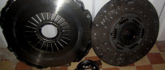
Many farmers are interested in how the MTZ-82 clutch is adjusted. On MTZ types 80, 82, 82-1, 320 and 1221 a single-disc clutch is installed. The function of such an element in the system is to transmit torque to the transmission from the engine. At this time, the engine is disconnected from the soft connection and the gearbox. At the same time, the clutch design of the MTZ-80 and other models allows the car to move smoothly and stop when the brakes are turned on.
How to adjust the clutch
Let's consider what this mechanism consists of. The clutch device includes friction discs pressed tightly against one another. These discs are located in the clutch. The transmission is engaged when the driving disc slips against the driven disc. They are connected to each other by a splined unit and a gearbox. When the pedal is released, the circuit turns on, and then the discs are pressed tightly together, and are separated when the pedal is pressed. At this moment, a gap appears between the disks.
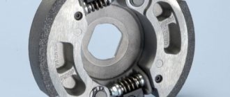
The MTZ-82 and 80 tractors from the Minsk plant have a single-disc, single-thread mechanism, which includes:
- flywheel;
- pressure and support disks;
- 12 pressure springs located between the discs.
Farmers ask how to install the clutch of the MTZ 80 tractor. Installation is carried out at the factory, but if repairs need to be made, you can do it yourself. The tractor is equipped with parts that can wear out during long-term use of the equipment. That is why the MTZ clutch is adjusted and the paw or disc is replaced.
MTZ LuK petal clutch
Several years ago, a unique new product appeared on the domestic market of auto-tractor spare parts - the German LuK clutch for tractors of the MTZ family. Until this point, the market supply of stores and wholesale warehouses was limited to clutch parts from the Bobruisk Tractor Parts and Assemblies Plant, which supplied the primary and secondary markets with MTZ driven and pressure plates, as well as release bearing couplings (layout). In addition, a number of manufacturers produce driven clutch discs (ferodo).
Since the MTZ clutch is a hot commodity, very soon cheap clutches from China appeared on the shelves, as well as “baskets” of handicraft production and “refurbished” ones from used parts. Moreover, a homemade clutch in appearance is difficult to distinguish from a factory one, and the consumer, at the price of the original, receives a low-quality, unbalanced product, in violation of geometric dimensions, heat treatment requirements and assembly standards. Obviously, only the seller was left with the profit from the sale of such a clutch, and the machine operator overpaid and once again “halved” the tractor.
That is why the consumer accepted the new product as an excellent replacement for the “conventional clutch.”
Adjusting the clutch feet
Let's look at how the MTZ-82 clutch paws are adjusted:
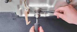
- First you need to unfasten the rod from the lever by extending your finger.
- Unscrew the MTZ-82 clutch adjustment bolt and set the pedal to its original position.
- After this, you need to unscrew the lever counterclockwise until the bearing stops, which is fixed into the release levers.
- Next, I adjust the traction fork, which will allow me to connect the hole of the lever and the fork.
- Reduce the thrust by 5 turns of the fork, then connect it to the lever using your finger.
- Check the health of the system.
It is necessary to adjust the clutch tabs on the clutch basket of the MTZ-80(82) tractor with the basket installed, while removing the transmission housing. The correct position of the foot is determined by a distance of 12 millimeters from the flange of the clutch support disk to the working plane of the lever-foot. This gap between the paws and the clutch disc must be set to the same; a minimum error of 0.3 mm is allowed.
The debugging test can be done by placing a flat, level plate or glass against the tabs. If they all touch the plate, then the adjustment is made correctly and the paws are in the same plane parallel to the flywheel.
You will be able to prevent such problems with the mechanisms of the tractor clutch system if the clearance of the feet is adjusted regularly:
- the disk will not warp;
- The paws will wear evenly.
Diagnostics of mechanism parts
To diagnose the condition of the coupling, you need to gain access to the unit. To do this, disconnect the engine from the transmission and roll out the tractor. Then an initial inspection of the unit is performed. Then unscrew the six nuts securing the basket to the flywheel and dismantle the assembly for a full inspection.
Release bearing condition
The bearing is replaced: the contact surface is worn out, it is noisy when rotating and has play in the races, the bearing is jammed.
Practitioners recommend that, in addition to the original bearing of the MTZ 80 tractor, you can install a KamAZ 5320 release bearing, which has proven itself in the operation of the tractor clutch mechanism.
When worn out at the contact areas of the bearing and fork drive, the parts can be restored by welding metal, followed by processing to the appropriate size.
Condition and degree of deterioration of the working surfaces of the feet and their integrity
When the working surfaces of the legs exceed 2.5 mm, they are replaced or welded on with subsequent processing.
When installing new paws, you need to pay attention to the contact plane of the levers with the release bearing. Often, castings of levers have non-identical contours and a contact surface; when applied to a bearing, they protrude beyond the working surface, capturing the part holder. In this case, the protruding part is ground off. When replacing paws, you also need to pay attention to the degree of metal hardness. One of the reasons for the rapid erasure of the feet after repair is the mismatch of the material used or the lack of hardening of the working surfaces of the part.
Condition of the foot springs
If broken springs are identified, all three springs are replaced.
Condition of the basket hub splines
If the splines are sufficiently worn or hub play appears, the basket is replaced.
Friction disc condition
If cracks, uneven wear, lifting of the linings, wear of the hub splines and play, loss of damper springs, as well as sufficient wear of the linings are detected, in all cases the disc is replaced.
Condition of the working plane of the basket pressure plate and the mounting holes for the paws
In case of uneven wear of the pressure plate, leveling by milling and grinding is allowed, taking into account the tolerance of the disk thickness of at least 21 mm. If the mounting holes for the release levers are broken into an ellipse, or if cracks are detected, the disc is replaced with a new one.
Flywheel contact plane condition
If acceptable ellipse of the flywheel surface is determined, alignment is carried out by milling and grinding. If the surface is worn too much, it must be replaced.
After defect detection of parts has been carried out, based on the condition, a decision is made: to carry out routine repairs of the unit with the replacement of worn parts or to replace the assembled unit.
How to change paws without rolling out the tractor
If you need to change the clutch feet, the working surface of which has worn out by more than 2.5 mm, without rolling out the tractor, you will need:
- new paws;
- file;
- screwdriver with short handle;
- a head stand for convenience (you can use a wooden block of suitable size).
Changing the paws without rolling out the tractor is quite simple, but it requires skill. First, remove the cover of the lower housing hatch by unscrewing the 3 bolts.
How to change the paws: press out the faulty levers and remove them by unscrewing the adjusting bolts; Use a file to slightly correct the unevenness of the contact surface of the new paws; install them and tighten the bolts; make adjustments and tighten the nuts; check the serviceability and close the lower hatch cover.
Let's now consider how to set the paws with a barbell.
This technique is used when the tractor was rolled out for repair.
In order to correctly align the tabs with the bar after replacing the release bearing, tabs or return springs, it is necessary to measure the distance from the plane of the PTO drive hub to the working plane of the basket clutch lever-claw. The gap should be 15 millimeters (±1 mm). Having tightened the adjusting bolts, we bring the contact surface of the clutch feet onto one plane and tighten the locknuts.
The next stage of repair of the MTZ-82 clutch involves moving the pedal to the initial position. To do this, you need to move the pedal to the full stroke length. If sagging is observed, you need to unscrew the bolts by turning the bracket clockwise.
If replacing the MTZ-82 clutch is not carried out by adjusting the rod length, then the position of the levers must be changed. When the adjustment is completed, tighten the locknut and secure the pin.
After adjusting the clutch, you need to start adjusting the release levers. Here you will need a frame that is made according to the inner diameter of the hub. It has an end surface designed to support the levers. They must be brought back to normal using nuts that will allow the levers to be brought all the way to the end, and lock washers installed.
Adjusting the clutch pedal free play.
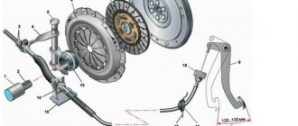
The pedal drive is regulated by changing the length of the drive rod 9 (in the figure) for clutch control, due to its threaded ends, providing a gap between the working plane of the release bearing and the claw levers. Correct adjustment gives the clutch pedal a free play of 40-45 mm, while the gap between the paws and the release bearing should be 3 mm. The adjustment is fixed using control nuts on the adjustable drive rod. The gap is measured through the lower hatch of the dry clutch housing with a feeler gauge of the appropriate size.
Current adjustment is carried out when the free play of the pedal decreases, compensating for the natural wear of the linings of the friction driven disk of the mechanism.
pedal free play adjustment
Often, machine operators adjust the position of the legs through the lower hatch of the housing, avoiding the time-consuming procedure of disconnecting the transmission from the engine or, popularly, rolling out the tractor. The position of the tabs is adjusted through the lower crankcase hatch when replacing a failed tab or its return spring. Such forced repairs are quite inconvenient due to poor accessibility to the basket mechanism, but are justified by saving time and labor costs. The disadvantage of this adjustment is the difficulty of checking its accuracy. Often adjustment is carried out “by eye”, which leads to misalignment of the planes of the clutch disks, uneven wear, a decrease in the efficiency of power transmission and, as a consequence, a decrease in the working life of the clutch mechanism.
How to adjust the clutch on a removed engine using a bar
You can adjust the clutch on an old-style MTZ-80 with the engine removed using a caliper.
- To do this, you need to measure the distance from the surface of the clutch disc to the washer with a caliper. If set correctly, it should be 2 mm (±0.1 mm).
- Measurements must be taken at several points.
- Then we unscrew the technological bolts and lock nuts. The nuts should be rotated carefully.
- We make adjustments.
- Reinstall the locknuts and bolts.
- Tighten without allowing the lock nuts to turn.
In order to adjust the MTZ-80(82) clutch feet through the hatch, you must:
- Turn off the tractor engine and put the handbrake on.
- Then remove the clutch hatch and, turning the engine crankshaft, “catch” the wringer with the adjusting screw through the hatch.
- Using a 3 mm feeler gauge, measure the gap between the release bearing and the tab; the feeler gauge should fit tightly.
- If the foot gap differs from the reference one, use a wrench and a screwdriver to turn the screw to the desired position.
- Carry out the procedure with the two remaining legs, turning the crankshaft 120 degrees.
- Close the hatch.
- How to check: the pedal travel will be free if the clearances are set correctly.
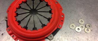
Design features of the MTZ LuK clutch:
133061010 MTZ LuK push clutch disc (basket).
| LuK clutch advantage | Consumer benefit |
| A fundamentally different design of the pressure plate is the use of a diaphragm spring (petal “basket”) instead of a complex, archaic scheme with “legs” and coil springs. The original “basket” 80-1601090 contains more than 180 parts! | There is no need to regularly adjust the release arms (feet). |
| Soft, smooth and controlled squeezing without jerking or twitching. | |
| The reliability of the clutch assembly is higher due to the smaller number of parts, simplicity of design and the absence of hinge joints. | |
| Perfect balance of the LuK pressure plate. | No vibration or beating. |
| The use of high-quality German steel in the support disk. | Strength, rigidity and reliability of the structure. |
| High precision and cleanliness of pressure plate processing. | No premature wear of the driven disk. |
Adjustment Tips
Additional tips and videos with visual examples will help you correctly adjust the clutch, adjust the clearance of the basket legs and generally maintain the mechanism in good condition for as long as possible.
- If repairs are required to replace spare parts, choose high-quality components;
- The clutch paws should be hardened; they will last you 2 times longer than unhardened ones;
- File the working surface of the new legs with a file before installation, as unevenness can often be found on them;
- Change the feet of the MTZ-80 clutch basket when the wear reaches 2.5 millimeters.
Consumer benefits of the MTZ LuK clutch:
- The MTZ LuK clutch resource exceeds a conventional clutch by 5-10 times (depending on operating conditions).
- Low pedal effort, soft and smooth squeezing is ensured by the use of a diaphragm spring, which replaced designs with coil springs for cars back in the 70s of the last century.
- Reduced amount of routine maintenance when servicing the clutch assembly (no need for adjustment) and for repair/replacement due to a longer service life.
- The ability to use the MTZ tractor in more severe operating conditions without losing useful torque and reducing the service life of transmission units.
- Effective damping of noise, vibrations and vibrations of transmission units, a positive effect on the service life of tractor parts and operator comfort.
- The production of LuK clutches is located exclusively in the European Union countries (Germany, Great Britain, Czech Republic, Italy). All production facilities are certified based on the most stringent quality management system requirements to date. The buyer is guaranteed to receive a first-class product.
- LuK clutches are supplied to the conveyors of tractor giants: Case IH, Claas, Mercedes-Benz, Farh, New Holland, JCB, John Deere, Lamborghini, Landini, Laverda, Massey-Ferguson, Renault, Same, Ursus, Valmet, Zetor and others.
You can buy an MTZ LuK clutch in Nizhny Novgorod by contacting us in a way convenient for you.
Transmission from A to Z - perfect contact
When does a mechanism need to be replaced?
Let's consider when there is a need to replace this mechanism. Replacement and repair of the MTZ-82 clutch is carried out in the following cases:
- The device does not allow you to obtain full torque.
- The pedal moves partially or the radius of its movement increases several times.
- The driven disc linings, lift brackets or cuffs are worn.
- Doesn't turn off completely.
- Oil gets onto a dry disc.
- The drive shaft bearing cap has been squeezed out.
Clutch malfunctions of the MTZ 82 tractor
1 Poor gear shifting with a grinding noise or inability to engage a gear. By squeezing the control pedal, the clutch is not completely disconnected.
Cause : Increased free play of the clutch pedal as a result of incorrect adjustment.
2 When the clutch is smoothly engaged, the tractor begins to move with a jerk.
Cause : Loss of damper springs or rubber bands from the driven friction disk of the mechanism.
3 Clutch slipping when the traction load on the tractor increases or the engine speed increases.
Cause : Incorrect adjustment - lack of pedal free play; wear of the friction linings of the driven disk; oil getting on the clutch discs as a result of a leak in the oil seal of the main bearing of the engine crankshaft, or oil seals in the tractor transmission.
4 Rumble, grinding, slipping, incomplete shutdown when the pedal is fully depressed; the transmitted rotation from the engine is accompanied by jerking and vibration.
Reason ; wear of the release bearing, wear of the working surfaces or breakage of the release levers, breakage of the springs of the release levers, wear of holes for the mounting pin of the levers, breakage or loss of damper springs and friction disk rubbers, wear of the driven disk linings, wear of the surface of the basket pressure disk (thickness less than 21mm), uneven wear of the engine flywheel surface, wear of the splines and play of the hubs of the basket and clutch disc, wear of the axle and drive levers of the release bearing pressure forks.
5 If, after adjustment, the mechanism does not perform its functions, or if it is impossible to adjust it, the unit is dismantled and then completely disassembled with defective parts.
In addition, it should be noted that the service life of the coupling depends on the technical condition of the support bearings of the power shaft. With increased play in the shaft support, the balance during rotation is disturbed, runout occurs in the hubs of the coupling mechanism, and as a result leads to breakdown.
Replacing the clutch yourself
To replace the clutch disc with your own hands, we suggest using the following algorithm:
- In order to avoid constant contact of the disk with the heads of the mounting bolts, it should be installed with its extended side facing the flywheel.
- Install the basket onto the flywheel stud bushings.
- Center the coupling.
- Tighten all nuts holding the clutch basket.
- Adjust the foot gaps.
- Connect the main parts of the tractor (engine and transmission) with the clutch assembly and tighten it.
The MTZ-80 clutch basket is repaired and adjusted in the same way. This wheeled tractor model, like the 1221 and 320, has the same reasons for clutch wear.
Correct installation of the clutch disc on MTZ 80(82)
- The driven friction disc is installed with the side with the extended part of the hub facing the engine flywheel, otherwise the damper springs will touch the heads of the flywheel mounting bolts.
- The clutch basket assembly is installed on six flywheel mounting studs with bushings.
- Align the clutch mechanism with a prepared false shaft or used one. shaft gaps.
- The six nuts securing the basket to the flywheel are tightened and the positions of the paw levers are adjusted.
- The transmission and engine are connected to the clutch mechanism by placing the shaft splines into the clutch hub splines.
- The connection between the housing and the engine crankcase is tightened.
If you are installing a new clutch mechanism, you must remember to unscrew the three technological mounting bolts from the basket body.
When communicating with professional machine operators, it is often discussed that the success of a repair depends on the quality of the spare parts purchased for replacement. There are a lot of products of dubious quality on the market. When selecting and purchasing, you need to pay attention to the compliance of the linear dimensions of the parts, seats, and the compliance of the material of manufacture, its hardening or carburization, grinding, if necessary, balancing.
How to make adjustments on MTZ-320
Let's look at how the clutch is adjusted on the MTZ-320 and how to correctly install the clutch disc. Like tractors such as MTZ-80, 82 and 82-1, the MTZ-320 has a dry single-disc friction clutch, which is of the permanently closed type.
The clutch is fixed to the flywheel with 6 bolts placed on three pins. The torque from the pressure disk and the flywheel of the motor passes to the driven disk, and then to the shaft. Between the release discs there are 9 pairs of springs.
The pedal can move freely in the basket, but the limit is 40 mm. If this parameter is larger, it will be difficult to shift the gearbox and problems will arise with the operation of the mechanism.
If the pedal travel is insufficient, slipping may well occur, which threatens wear on the discs.
You can cope with this situation by installing the MTZ-320 clutch. This is done according to the following scheme:
- You need to unfasten the rod from the lever and pull out the finger.
- Rotate the lever counterclockwise until the bearing stops in the lever. Then you need to turn the traction fork, connect the holes on the lever and the fork.
- You need to turn the fork a few turns and try to connect it to the lever, for which you need to use your finger.
- At the very end of the contract, the finger is secured.
- After this, it is necessary to check the serviceability of all components and fasteners that are included in this system of the MTZ mini-tractor.
When adjusting the MTZ-1221 clutch, adjust all the devices that together make up the MTZ clutch. Unlike the models of mechanisms installed on MTZ-80, 82 and 320, clutch adjustment on 1221 involves working with a different type of system.
This tractor model has a double-disc friction mechanism with a pressure disc called a basket. The driven part of the system also includes 2 driven ones, on which there are rotation vibration dampers. They are located on the power shaft, which ensures an effective connection.
Before installing a new clutch on Belarusian mini-tractors, you must first remove it. First, bolts are installed, which are screwed into the pressure plate. Secondly, the fastening nuts are unscrewed and the discs are removed. Thirdly, first the slave is removed, then the middle slave, and at the very end the second slave.
The adjustment involves first installing a splined mandrel into the flywheel bearing. Then the first driven one is installed, and then the one that is mounted in the grooves of the flywheel.
Next, the second slave is installed, after which it is necessary to put in place the disks that are assembled. They must be secured with nuts and bolts. At the very end, the position of the release levers is adjusted.
In order for the release levers to fall into place, you need to alternately screw in and unscrew the adjusting nuts and put them on the other side. When the repaired levers can be controlled, it is necessary to install the locking plates and remove the frame.
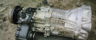
Tractor clutch Belarus 80.1/82.1/820
Tractor clutch Belarus 80.1/82.1/820
A dry single-plate clutch of a permanently closed type is installed on flywheel 1 (Figure 1) of the engine.
The driving part of the clutch is the flywheel 1 and the pressure plate 3. The driven part of the clutch includes the driven disk 2 (with asbestos-free linings) with a torsional vibration damper 8, mounted on the power shaft 6.
On the BELARUS-80.1/82.1/820 tractors, the required pressing force on the rubbing surfaces of the driving and driven parts is provided by nine springs 20.
Elastic elements are installed between the floating bushing 7 connected to the PTO drive shaft 4 and the support disk 10. The clutch is turned on and off by a tap 16 with a release bearing 14 moving along a bracket 15. The tap fork 17 with a roller 18 is connected by a rod to the clutch pedal.
The release bearing 14 is lubricated through a grease nipple screwed into the release pin.
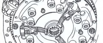
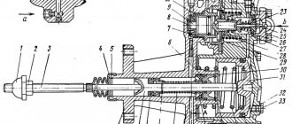
Clutch for tractors "BELARUS-80.1/82.1/820"
1 – flywheel; 2 – driven disk; 3 – pressure disk; 4 – PTO drive shaft; 5 – hub; 6 – power shaft; 7 – floating bushing; 8 – torsional vibration damper; 9 – release lever; 10 – support disk; 11 – fork; 12 – nut; 13 – locking plate; 14 – release bearing; 15 – layer bracket; 16 – layer; 17 – shutdown fork; 18 – control roller; 19 – glass; 20 – pressure spring; 21 – insulating washer.
Figure 1 – Clutch of tractors “BELARUS-80.1/82.1/820”
Clutch for tractors BELARUS-80.1/82.1/820
1 – flywheel; 2 – driven disk; 3 – pressure disk; 4 – floating bushing; 5 – release lever; 6 – support disk; 7 – locking plate; 8 – adjusting nut; 9 – fork; 10 – bushing.
Figure 2 – Installation, dismantling and adjustment of clutch release levers Belarus 80.1/82.1/820
Technological mandrel for adjusting the MTZ 80.1/82.1/820 clutch
Figure 3 – Technological mandrel
Dismantling the clutch is carried out after disconnecting the engine from the transmission in the following order:
— install three technological bolts (M12×40), screwing them into pressure disk 3 (Figure 2) through the technological holes of support disk 6;
— unscrew the nuts securing the support disk to the flywheel and remove the clutch disc assembly (support 6 with pressure 3);
— remove driven disk 2.
Installation of clutch Belarus 80.1/82.1/820
Installation of the clutch is carried out in the following order:
— install driven disk 2 (Figure 2) with the long end of the hub to flywheel 1;
— install the clutch disc assembly (support 6 with pressure 3) on the fingers
flywheel with bushings 10, secure with nuts (tightening torque from 70 to 90 Nm);
— install the technological mandrel and unscrew the technological bolts.
— adjust the position of the release levers 5.
Adjusting the clutch release levers
The clutch release levers must be adjusted as follows:
— by screwing or unscrewing the adjusting nuts 8 (Figure 3.2.2), adjust the position of the release levers to a size of 13±0.5 mm from the supporting surfaces of the levers to the end of the support disk hub. The difference in size for individual levers should be no more than 0.3 mm;
— after adjusting the levers, install locking plates 7 and secure them with bolts;
- remove the mandrel.
The MTZ 80.1/82.1/820 clutch is controlled as follows:
When you press the pedal pad 6 (Figure 4), the rod 5 moves and turns the lever 1, connected through the control shaft 18 (Figure 1) with the clutch release. The clutch is then disengaged. When pedal 6 is released (Figure 4), the clutch is engaged.
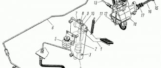
Clutch control MTZ 80.1/82.1/820
a) without creeper b) with creeper
1 – lever; 2 – finger; 3 – fork; 4 – lock nut; 5 – traction; 6 – pedal; 7 – servo device; 8 – bolt; 9 – bracket; 10 – cover; 11 – washer; 12 – creeper.
Figure 4 – Clutch control
Adjusting the free play of the clutch pedal
ATTENTION: TOO LONG PEDAL TRAVEL WILL NOT ALLOW THE CLUTCH TO BE COMPLETELY DISENGAGED AND MAKE IT DIFFICULT TO SHIFT GEARS. THE LACK OF FREE STROKE OF THE PEDAL WILL CAUSE SLIPPING OF THE CLUTCH DISCS, RAPID WEAR OF THE DISCS AND OVERHEATING OF THE CLUTCH PARTS!
The free play of the clutch pedal, measured with the engine not running, should be in the range from 40 to 50 mm. If this value is exceeded or underestimated, adjust the clutch pedal free play.
To adjust the free play, do the following:
— loosen lock nut 4 (Figure 4) of fork 3, unpin and remove pin 2, disconnecting rod 5 from lever 1;
— unscrew the adjusting bolt 8 until pedal 6 touches the cabin floor;
— turn lever 1 counterclockwise until it stops, i.e. until it touches the release
MS release lever bearings;
— adjust the length of rod 5 by rotating fork 3 until the holes in the fork and lever 1 coincide. Then screw in fork 3 five turns (shorten the rod).
— tighten locknut 4, connect fork 3 to lever 1 using pin 2.
If your tractor is equipped with a creeper, then to prevent the pedal 6 from freezing, you need to install up to four washers 11. The free play of the clutch pedal can be reduced to 35 mm.
ATTENTION: ENSURE THAT THE CLUTCH PEDAL IS RELIABLY RETURNED TO THE PEDAL IN THE PEDAL FREE ROLL AREA. OTHERWISE, ADJUST THE SPRING FORCE OF SERVO DEVICE 7 (FIGURE 4) USING BOLT 8 OR CHANGE THE POSITION OF BRACKET 9 BY TURNING IT COUNTERCLOCKWISE RELATIVE TO THE AXIS OF THE MOUNTING BOLT!
The clutch housing of the BELARUS-80.1/82.1/820 tractors can be equipped with a mechanical reduction gearbox (Figure 5), a reverse gearbox (Figure 6), and a synchronized reduction gearbox (Figure 3.2.7).
Clutch housing 7 (Figure 5-8) can be divided into two parts: the dry compartment and the gear part.
In the dry compartment of the clutch housing there is a clutch mounted on the flywheel 1 of the engine. On the release bracket 6, also located in the dry compartment, a release with release bearing 5 is installed; the release pins fit into the eye of the clutch release forks 3. A grease fitting is screwed into one of the release pins, designed to lubricate the release bearing.
The gear part includes an independent two-speed rear PTO drive, a hydraulic pump pump drive and a reduction gearbox.
The independent two-speed PTO drive is designed to obtain two rotation modes on the power take-off shaft shank: 540 min-1) and 1000 min-1). The drive shaft-gear 30 of the PTO drive, mounted on two bearings 8 and 12, is connected through splines to the floating sleeve 2 of the clutch support disk and is in constant engagement with two driven gears of the PTO drive 26 and 27.
The driven gear 27 of the 540 min-1 drive) is installed on the driven shaft of the PTO drive 22 on two needle bearings with an outer race 28. The driven gear 26 of the 1000 min-1 drive is installed on the driven gear 27 on two ball bearings 25). The transmission of torque from the driven gears to the driven shaft 22 is carried out through a gear coupling 24 mounted on the splines of the driven shaft. The gear coupling is engaged with one of the gears using a control shaft 23.
The GNS pump is driven by gear 10 mounted on two ball bearings 9 of axis 11. Drive gear 10 is in constant mesh with gear shaft 30.
The reduction mechanical gearbox (Figure 5.) is designed to obtain an additional range of speeds necessary for working with agricultural machines. The reduction gear is located between the clutch housing and the gearbox. On the power shaft 14 of the clutch housing, a connecting gear coupling 19 is mounted movably on splines. When the gear coupling 19 is
control mechanism 18 engages with the drive gear of the gearbox 16, mounted on the power shaft on rollers 17, then the reduction gearbox is turned on (lower stage of the reduction gearbox). If the gear coupling engages with the driven gear 20 mounted on the splines of the input shaft of the gearbox, then the reduction gear is turned off (increased stage of the reduction gear). The shift lever for the reduction gearbox is located in the tractor cabin.
Clutch housing with mechanical reduction gear MTZ 80.1/82.1/820
1 – flywheel; 2 – floating bushing; 3 – fork; 4 – hub; 5 – release bearing; 6 – branch bracket; 7 – clutch housing; 8, 9, 12, 13, 15, 25, 29 – bearing; 10 – GNS pump drive gear; 11 – axis; 14 – power shaft; 16 – drive gear of the reduction gearbox; 17 – rollers; 18 – gearbox control mechanism; 19 – gear coupling; 20 – driven gear of the reduction gearbox; 21, 28 – needle bearing with outer race; 22 – driven shaft of the PTO drive; 23 – control roller; 24 – gear coupling; 26 – driven gear of the PTO drive (mode 1000 min-1)); 27 – driven gear of the PTO drive (mode 540 min-1)); 30 – drive shaft-gear of the PTO drive.
Figure 5 – Clutch housing with mechanical reduction gear
The reverse gearbox (Figure 6.) is designed to change the direction of movement of the tractor. The reverse gearbox is located between the clutch housing and the gearbox. A synchronizer 18 is installed on the input shaft of the gearbox. The synchronizer carriage, controlled by the control mechanism 17, can engage with the driven gear of the reverse gearbox 19 (reverse movement) or with the drive gear of the reverse gearbox 16 (forward movement). The reverse gear shift lever is located in the tractor cabin. By moving the lever forward in the direction of movement of the tractor, forward movement is activated. When you shift the lever back, you move in reverse.
Clutch housing with reverse gearbox MTZ 80.1/82.1/820
1 – flywheel; 2 — floating bushing; 3 – fork; 4 – hub; 5 – release bearing; 6 – branch bracket; 7 – clutch housing; 8, 9, 12, 13, 15, 27, 31 – bearing; 10 – hydraulic system pump drive gear; 11 – axis; 14 – power shaft; 16 – drive gear of the reverse gearbox; 17 – reverse gear control mechanism; 18 – synchronizer; 19 – driven gear of the reverse gearbox; 20 – ball; 21 – reverse gear idler gear; 22-needle bearing; 23, 30 – needle bearing with outer race; 24 — driven shaft of the PTO drive; 25 – control roller; 26 – gear coupling; 28 – driven gear of the PTO drive (mode 1000 rpm); 29 — driven gear of the PTO drive (mode 540 rpm); 32 – drive shaft-gear of the PTO drive.
Figure 6 – Clutch housing with reverse gear
The synchronized reduction gearbox (Figure 7) is designed to provide an additional range of speeds necessary for working with agricultural machines. The gearbox is located between the clutch housing and the gearbox. A synchronizer 18 is installed on the input shaft of the gearbox. The synchronizer carriage, controlled by the control mechanism 17, can engage with the driven gear of the reduction gearbox 19 (lower stage of the reduction gearbox) or with the drive gear of the gearbox 16 (increased stage of the reduction gearbox). The shift lever for the reduction synchronized gearbox is located in the tractor cabin.
Clutch housing with synchronized reduction gearbox MTZ 80.1/82.1/820
1 – flywheel; 2 — floating bushing; 3 – fork; 4 – hub; 5 – release bearing; 6 – branch bracket; 7 – clutch housing; 8, 9, 12, 13, 15, 25, 29 – bearing; 10 – hydraulic system pump drive gear; 11 – axis; 14 – power shaft; 16 – drive gear of the reduction gearbox; 17 – gearbox control mechanism; 18 – synchronizer; 19 – driven gear of the reduction gearbox; 20 – ball; 21, 28 – needle bearing with outer race; 22 — driven shaft of the PTO drive; 23 – control roller; 24 – gear coupling; 26 – driven gear of the PTO drive (mode 1000 rpm); 27 – driven gear of the PTO drive (mode 540 rpm); 30 – drive shaft-gear of the PTO drive.
Figure 7 – Clutch housing with synchronized reduction gear
How to avoid system wear
During operation of the mechanism, you must carefully monitor the condition of the coupling. Among the main recommendations it is worth noting the following:
- Every 60 hours of movement, the mechanism must be completely lubricated.
- Carry out a full pedal free play inspection every 240 hours.
- Use grease as a lubricant.
- It is necessary to monitor the size of the freewheel; it decreases over time due to wear of parts. The maximum free play should not be more than 30 mm. If necessary, the clutch disc is installed or replaced.
On Belarusian tractors, the installation diagram provides for compliance with the following rules of use:
- When the machine is moving, the operator working on the tractor should not press the pedal for a long time. Otherwise, the wear rate of parts may increase.
- The clutch must be moved smoothly. It is forbidden to leave it in an intermediate state for a long time.
- You cannot keep the clutch turned off for a long time, which has a bad effect on the operation of the mechanism.
- The pads should be checked every 120 hours of driving, as they reduce the pedal travel of the mechanism.
- Check the stroke of the lever, which should be located at a distance of 6-7 mm. This corresponds to the free travel of the pedal, the size of which varies from 40 to 50 mm.
Thus, clutch adjustment on MTZ-80 and 82 differs from repair of MTZ-1221, since it has a more modern system and design. After familiarizing yourself with this material, each farmer will be able to independently adjust the clutch on his tractor and, if necessary, replace or repair the relevant parts. This will save money.
General information
The tractor design uses a four-cylinder diesel engine and a multi-speed gearbox. Between these units there is a clutch assembly, which requires regular maintenance. Adjusting the clutch on the MTZ-82 allows you to ensure that the power and traction indicators of the tractor comply with the factory documentation. The performance of the equipment depends on the correctness of the set gap in the mechanism, since when the clutch wears out, it begins to slip, which causes faster and faster wear of the unit.
Key Points: How to Correctly Adjust the Clutch System
The mechanism is structurally a pair of friction discs tightly pressed against each other, mounted on a clutch. The transmission is activated by the sliding of the driving element towards the driven element. Both parts are secured by the gearbox and spline assembly. As soon as the operator releases the pedal, the circuit turns on, causing the discs to be pressed. If the driver presses, the elements move apart, forming a gap.
The manufacturer installs a single-flow system on MTZ 80, 82 tractors, which includes:
- flywheel;
- two disks (pressure and support);
- compression springs in the amount of 12 pieces.
The machine's clutch is installed and adjusted at the factory. However, during repairs it may be necessary to install the system. If some parts have become unusable due to prolonged work in difficult conditions, you can put the mechanism in order on your own.
The clutch paws are adjusted as follows:
- unfasten the rod from the lever;
- Unscrew the bolt that is designed to adjust the clutch;
- put the pedal in its original position;
- unscrew the lever until it stops (counterclockwise only);
- adjust the rod fork to connect the hole of the lever, the fork itself;
- reduce thrust by five turns;
- connect the fork and lever;
- check the functionality of the system.
Next, you need to move the clutch pedal to its original position. Pull it back to full stroke length. If you notice any sagging, tighten the bolts.
Sometimes it is not possible to adjust the clutch by adjusting the rod length. Then it is necessary to change the position of the levers. After completing all manipulations, tighten the locknut and secure the pin.
A special frame is used for adjustment. Install it with the end surface to the lever stops, tighten it until it stops, and secure it with lock washers.
Typical faults
One of the most common problems is incomplete supply of torque from the engine flywheel to the wheels. The reason for this may be the lack of free play in the pedal, which should be set when adjusting the clutch on the MTZ-82. With an increased stroke, the friction discs are not completely retracted, which causes difficulty switching gears. A characteristic sign of such a problem is the grinding of gears when switching.
The owner and driver of the tractor must remember that operating equipment with an unadjusted clutch will lead to breakdowns of many components and costly repairs. In addition, the equipment will be idle, which is unacceptable if urgent work is necessary (for example, during harvesting or sowing).
Source
Check and possible malfunctions
Like any moving mechanical unit, the clutch is subjected to strong and serious workload during operation, which sooner or later leads to failures and breakdowns.
It doesn’t take much intelligence to determine that the clutch system of a Belarusian tractor is functioning properly. Remember two main signs of its high-quality work:
- When the clutch is operating, the discs do not slip relative to each other, sending regular force from the diesel engine;
- When you depress the pedal, you should immediately feel that the clutch is completely disengaged.