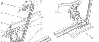
To raise and lower the KamAZ cab, a pump mounted on the vehicle frame is used (see Fig. Mechanism for raising and lowering the cab). The position of the handles for raising and lowering the cabin is indicated on the plate located on the pump body, see fig. Control knob position plate or Control knob position plate (option) ).
Mechanism for raising and lowering the cabin 1 - control handle, 2 - tipping mechanism pump, 3 - pump handle, 4 - pump probe, 5 - cabin wing, 6 - right spar, 7 - tipping device cylinder, 8 - right longitudinal cabin beam, 9 -bracket
During the operation of a KamAZ vehicle, it is necessary to ensure control over the oil level in the hydraulic lift system. The oil level should be between the marks indicated on the pump dipstick mounted in the pump reservoir housing.
| Control knob position label | Control knob position plate (optional) |
Raising the cab to the first position provides access to the engine during its maintenance. Before raising the cab you must:
- brake the car with the parking brake system;
- set the gear shift lever to the neutral position (for gearboxes of models 142, 144, 152, 154 to the neutral middle position of engaging 2nd - 3rd gears);
- lift the front facing panel;
- for a cabin equipped with locking devices, turn up the handles of both cabin locks (see Fig. Cabin locking device), release the safety hook; for a cabin with hydraulic locks, the hydraulic locks open automatically when the pump is running.
Cabin locking device 1 - locking handle handle; 2 — cabin lock body; 3 — safety hook bracket; 4 spring; 5 — safety hook; 6 - finger; 7 — constipation axis; 8 - hook; 9 — locking handle; 10 bracket; 11 — rubber cushion; 12 — bracket
To raise the cabin, set the handle on the hydraulic cabin lift pump, depending on its model, to the cabin lift or up arrow position and, shaking the pump handle with a mounting blade, raise the cabin.
When raising the cabin (by approximately 40°), it is necessary to check the straightening of the rack and the alignment of the holes in the lower and upper racks. If these holes coincide, stop raising the cabin. To prevent accidental lowering of the cab, secure the limiter posts with a safety pin (see Fig. Cabin post).
To lower the cabin, remove the safety pin, set the handle on the pump, depending on its model, to the cabin lowering or down arrow position and, shaking the pump handle with a mounting blade, begin lowering the cabin, then insert the pin into the transport position into the hole in the lower stop post, lower cabin Close the handles of the right and left locking devices.
For a cab with hydraulic locks, they should lock when the cab is lowered. If at least one of the two hydraulic locks is not latched, the warning lamp located on the instrument panel lights up.
To raise the cabin to the second position, raise the cabin to the first position (see above). Undo the pin and remove the pin from the bracket (see Fig. Cabin pillar). Use a hydraulic lift to raise the cabin to the second position.
To raise the cabin to the second position to remove the engine, remove the buffer, lift the front facing panel and raise the cabin to the first position. On vehicles equipped with a KAMAZ engine, starting with environmental class 2, and a non-adjustable steering column, disconnect the driveshaft from the steering mechanism shaft and secure it in a position that prevents damage to steering parts when raising and lowering the cab.
Hydraulic cylinder device for lifting the MAZ cab
The piston type mechanism consists of a shut-off valve.
The hydraulic cylinder of the MAZ cab is part of the tilting system of cabover cars. The lifting device provides unobstructed access to the engine. When the mechanism handle is installed in the “Lift” position, the hydraulic cylinder of the MAZ cab acts on the cams. Details are revealed. The element then raises the cabin. To return the mechanism to its original position, you need to set the lever to “Lower”.
The locking mechanisms open automatically. The process occurs during lifting thanks to the hydraulic cylinder of the MAZ cab.
If it is necessary to remove the pump or other mechanism of the tipping system, first disconnect the pipes. Be sure to remove the battery. Unscrew the fasteners.
The hydraulic cylinder for lifting the MAZ cab is responsible for transmitting and distributing the force of the tipping mechanism. If the climb is difficult or incomplete, repairs are necessary.
Mechanical wear causes the sleeves, seals and rods of the MAZ cabin lift hydraulic cylinder to fail. In such cases, diagnosis is necessary. Repairs are performed using special equipment. However, if you have the appropriate skills, independent repairs are possible.
To dismantle the part, carefully disconnect the pipelines, as well as:
- The finger is removed.
- Remove the cylinder by unscrewing the bolt.
- All dismantling work is carried out with the cabin in its highest raised position. Be sure to use a safety rope.
When choosing a new MAZ cab lift hydraulic cylinder, they are guided by technical characteristics. Take into account the manufacturer's recommendations. For uninterrupted operation of the lifting mechanism, I use only original hydraulic cylinders.
Source
How the cabin works
The cabin is equipped with various systems, such as electronics, heating, air conditioning, which creates a comfortable environment for the operator.
- for comfortable working conditions;
- to create a microclimate;
- to protect the operator from vibrations;
- to ensure driver rest;
- to create good visibility of the road surface.
Recently, the design of the MAZ cabin has been improved; soft seats, an upper berth, and springs under the driver's seat have appeared. The modern design consists of a frame, cladding and a tipping unit. Metal frame. In terms of overall dimensions, the structure can be small or large. The first one has no sleeping space.
These vehicles are used in cities for short-distance transportation. Oversized structures are installed on tractors; they have one or two berths. The basis of the structure is a welded metal frame. The frame is assembled from two sidewalls, two parts, a floor and a roof. Then they install doors equipped with side shields to protect the openings. The instrument panel is installed under the windshield. A windshield frame reinforcement has been added. There are 3 windshield wipers.
The interior trim hides the components of the radiator and other mechanisms. Since 1990, the interior has been equipped with plastic sidewalls and additional systems. The cladding is equipped with thermal insulation. At the front are the instrument panel and the ducts for supplying warm air from the heater. The seat is height adjustable.
Shock absorbers in the form of rubber bushings eliminate vibration. The cabin is tipped by a hydraulic cylinder spring. To activate the unit, press the lever. A thin cable protects the structure from excessive tipping.
MAZ hydraulic cylinder for raising the cab - review
The driver's seat in MAZ trucks is located directly above the power plant; many parts of the engine and auxiliary systems are closed for access. Therefore, cars are equipped with a tilting cab. For lifting, a MAZ 6430 5003010 hydraulic cylinder is used. In this article we will talk about the design of the system, as well as the operating features.
Don’t forget that you can buy a MAZ hydraulic cylinder for lifting a truck cab in our catalog.
We will provide fast delivery to any city in Russia and the most favorable payment terms.
Device 6430 5003010 10
The part is distinguished by its simplicity of design and a good coefficient of increase in the applied force. The design of the mechanism consists of:
- Housings;
- Rod with fastening in the form of a stop and a piston;
- Containers for working fluid, which uses oil;
- Pipe connections of the main cavity with the oil tank;
- A drive handle connected to the plunger via a crank.
Also included are several valves of different directions, as well as a regulator-switch. Most often, the hydraulic cylinder 6430 5003010 10 also uses a filter that cleans the oil.
Features of operation and repair of the unit
The operating principle of the MAZ hydraulic cylinder for lifting the cab looks like this:
- If lifting is necessary, the regulator moves to the appropriate position;
- By pumping the pump handle, one valve opens;
- Oil fills the lower part of the housing;
- As the volume of liquid increases, pressure increases;
- The force is transferred to the piston, which pushes out the rod.
The bottom of the cylinder automatically goes into the frame beam, the upper part of the rod goes into contact with the cabin, and it rises. The front of the cabin has hinged fasteners, this makes it possible to lift and turn in an arc.
If the hydraulic cylinder malfunctions, the part must be replaced. If the valves lose their tightness or the stem is deformed, the mechanism can usually be repaired. Analogues of 6430 5003010 010 are produced by several manufacturers, but it is best to purchase components recommended by the manufacturer.
On our website you will find a wide range of hydraulic cylinders - these are parts with catalog numbers 6430 5003010, 6430 5003010 10, 6430 5003010 010 and their analogues.
Not available:
| № | Part code | Name | Part Information |
| 64221-5004020 | Filler plug | Quantity 1 Model 64221 Group Cabin (Body) Subgroup Upholstery and casings Serial part number 020 | Not available |
| 64221-5004040 | Jet spool | Quantity 1 Model 64221 Group Cabin (Body) Subgroup Upholstery and casings Serial part number 040 | Not available |
| 64221-5004060-01 | Filter | Quantity 1 Model 64221 Group Cabin (Body) Subgroup Upholstery and casings Serial part number 060 | Not available |
| 64221-5004012 | Spring | Quantity 1 Model 64221 Group Cabin (Body) Subgroup Upholstery and covers Serial part number 012 | Not available |
| 64221-5003057 | Emphasis | Quantity 1 Model 64221 Group Cabin (Body) Subgroup Sidewall Part serial number 057 | Not available |
| 64221-5004016 | Pump housing | Quantity 1 Model 64221 Group Cabin (Body) Subgroup Upholstery and casings Serial part number 016 | Not available |
| 64221-5004021 | Pump base | Quantity 1 Model 64221 Group Cabin (Body) Subgroup Upholstery and casings Serial part number 021 | Not available |
| 64221-5004026 | Cylinder | Quantity 1 Model 64221 Group Cabin (Body) Subgroup Upholstery and casings Serial part number 026 | Not available |
| 64221-5004027 | Plunger | Quantity 1 Model 64221 Group Cabin (Body) Subgroup Upholstery and casings Serial part number 027 | Not available |
| 18-5004028 | Cuff | Quantity 1 Model 18 Group Cabin (Body) Subgroup Upholstery and casings Part number 028 | Not available |
| 64221-5004029 | Protective washer | Quantity 1 Model 64221 Group Cabin (Body) Subgroup Upholstery and casings Serial part number 029 | Not available |
| 64221-5004031 | Plunger spring | Quantity 1 Model 64221 Group Cabin (Body) Subgroup Upholstery and casings Serial part number 031 | Not available |
| 64221-5004036 | Lever arm | Quantity 1 Model 64221 Group Cabin (Body) Subgroup Upholstery and casings Serial part number 036 | Not available |
| 64221-5004041 | Shaft | Quantity 1 Model 64221 Group Cabin (Body) Subgroup Upholstery and casings Serial part number 041 | Not available |
| 64221-5004044 | Video clip | Quantity 1 Model 64221 Group Cabin (Body) Subgroup Upholstery and casings Serial part number 044 | Not available |
| 64221-5004046 | Valve body | Quantity 1 Model 64221 Group Cabin (Body) Subgroup Upholstery and casings Serial part number 046 | Not available |
| 64221-5004054 | Valve washer | Quantity 1 Model 64221 Group Cabin (Body) Subgroup Upholstery and casings Serial part number 054 | Not available |
| 64221-5004058 | Cork | Quantity 1 Model 64221 Group Cabin (Body) Subgroup Upholstery and casings Serial part number 058 | Not available |
| 64221-5004058-01 | Cork | Quantity 1 Model 64221 Group Cabin (Body) Subgroup Upholstery and casings Serial part number 058 | Not available |
| 64221-5004072 | Limiter | Quantity 1 Model 64221 Group Cabin (Body) Subgroup Upholstery and casings Serial part number 072 | Not available |
| 64221-5004082 | Limit washer | Quantity 1 Model 64221 Group Cabin (Body) Subgroup Upholstery and casings Serial part number 082 | Not available |
| 64221-5004086-20 | Support | Quantity 1 Model 64221 Group Cabin (Body) Subgroup Upholstery and casings Serial part number 086 Additionally Not interchangeable with a part previously released under the same number | Not available |
| 64221-5004094 | Locking bolt | Quantity 1 Model 64221 Group Cabin (Body) Subgroup Upholstery and casings Serial part number 094 | Not available |
| 500-3918112 | Locking ring | Quantity 1 Model 500 Group Driver's tools and accessories Subgroup 3918 Part number 112 | Not available |
| 200317 | Bolt M10-6gх45 | Quantity 2 Coated uncoated | Not available |
| 201500 | Bolt M10-6gх32 | Quantity 2 Coated uncoated | Not available |
| 252006 | Washer 10 | Quantity 2 Coated uncoated | Not available |
| A-10-04-19 | Washer A.10.04.19 | Quantity 2 | Not available |
| 252136 | Washer 10.OT | Quantity 4 Coated uncoated | Not available |
| 258038 | Cotter pin 3.2x16 | Quantity 1 Coated uncoated | Not available |
| 258630 | Pin 5x25 | Quantity 2 Coated uncoated | Not available |
| 260061 | Finger 10x38 | Quantity 1 Coated uncoated | Not available |
| 400337 | Retaining ring | Quantity 1 Coated uncoated | Not available |
| 6-20 | Ball | Quantity 2 | Not available |
| 6-60 | Ball | Quantity 2 | Not available |
| 015-019-25-2-3 | Ring | Quantity 1 | Not available |
| 018-022-25-2-3 | Ring | Quantity 1 | Not available |
| 020-024-25-2-3 | Ring 020-024-25-2-3 | Quantity 3 | Not available |
| 022-028-36-2-3 | Ring | Quantity 1 | Not available |
| 025-031-36-2-3 | Ring | Quantity 1 | Not available |
| 066-071-30-2-3 | Ring | Quantity 1 | Not available |
More drawings and projects on this topic:
Contents: Set of documents for the technological process of machining the “Bottom” part (TP), Non-adjustable hydraulic shock absorber (before modernization) (SB), Adjustable shock absorber for a MAZ bus (after modernization) (SB), Comparative analysis of an adjustable shock absorber for a MAZ bus with a basic one non-adjustable design (СХ), Rod with seal and piston (СБ), Detailing (compression valve, body nut, oil seal housing, piston, rod, Bottom), Three-jaw chuck with hydraulic drive (СБ), Technical and economic indicators (СХ)
Source
Repair of MAZ cabin hydraulic cylinder
If the mechanism fails, contact a specialized service station. The service center will check the hydraulic cylinder of the MAZ cab and make the necessary repairs. Specialists will remove and install the piston. Check the lubrication in the hydraulic system. The device will be washed and tested.
Gasket rupture occurs under excessive loads. If there is no pressure in the piston cavity of the MAZ steering hydraulic cylinder, check the seals. If gaskets are damaged, replace. If there are oil leaks along the rod, install new seals.
If the rod heats up or the part moves unevenly with noticeable vibrations, check the fastenings. Due to large lateral loads, the connection became loose. When eliminating the defect, ensure that the rod is aligned with the drive mechanism.
If the part moves jerkily and noise is heard, air has entered the hydraulic cylinder of the MAZ cab. It is necessary to check the pipelines and seals. Eliminate air and eliminate suction in connections.
The bent rod is straightened on the press. Check the chrome parts. The rod is processed or a new rod is purchased for the MAZ hydraulic cylinder.
After repairing the cylinder, all parts are cleaned of dirt. Spare parts are washed with a special solution. Before assembly, blow with compressed air. The quality of washing is monitored visually. Seals and cuffs are lubricated. Check the tightness of the cuffs. Remove traces of corrosion and defects. After assembly, the rod should rotate freely. Before installation, the hydraulic cylinder is tested on a bench. Check strength, external tightness and idle operation.
If the mechanism cannot be repaired, buy a MAZ hydraulic cylinder along with a repair kit in our catalog. Fast delivery, reasonable prices, free consultation on product selection - we will offer you the best conditions for purchasing spare parts.
Source
What is a cab tilt cylinder?
The cab tilting mechanism cylinder (MOK cylinder, MOK hydraulic cylinder) is an actuator for the cab tilting mechanism of trucks with a cabover layout; Double-acting hydraulic cylinder for raising and lowering the cab.
The MOK cylinder has several functions:
- Raising the cabin for maintenance or repair of the engine and other systems;
- Assists the balancing mechanism in supporting the cab in an inverted position;
- Smooth lowering of the cabin without jolts or jerks.
Specifications
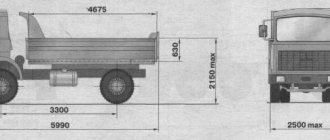
MAZ-5551 is a two-axle dump truck with a 2x4 wheel arrangement and double tires on the rear wheels. The body is all-metal, with automatic opening and closing of the tailgate. Unloading of the dump truck in the basic configuration is rear. The engine is located longitudinally, under the cabover cab. All power elements are fixed to a metal frame.
Engine
Most often, modern MAZs are equipped with four-stroke power plants manufactured in Yaroslavl YaMZ-6563.10-03.
- Type – with compression ignition and direct fuel injection;
- Working volume – 11.15 l;
- Number and arrangement of cylinders – 6, V-shaped;
- Compression ratio – 17.5;
- Power – 230 hp (169 kW);
- Maximum torque at a crankshaft speed of 1100-1300 rpm – 90 Nm;
- Minimum specific fuel consumption – 200 g/kWh;
- Turbocharging system – with intermediate cooling of charge air. Air-to-air heat exchanger.
The engines are equipped with a Yazda fuel supply system with a Compact-40 fuel injection pump. The engine ensures compliance with EURO-3 environmental standards.
Fuel consumption
The fuel consumption of the MAZ-5551 is 22 l/100 km. Taking into account the large capacity of the fuel tank (200 l), the truck can cover over 800 km without additional refueling.
Chassis
The front suspension is made on two semi-elliptical springs with double-acting hydraulic shock absorbers. The rear suspension is on two main and two additional springs with anti-roll bar. The brake mechanisms are drum. The drive of the main brake system is pneumatic, separately for the front and rear wheels. Parking brake - on the rear wheels with pneumatic drive, from spring energy accumulators. The car is equipped with tires of size 12.00R20 mod. ID-304.
Power transmission
In the basic configuration, the car is equipped with a five-speed manual transmission YaMZ-236P. Synchronizers are installed in 2nd, 3rd, 4th, and 5th gears. The transmission of torque from the engine to the transmission elements is carried out by a double-disc friction clutch. The clutch drive is hydraulic with a pneumatic booster. The rear axle is a double transmission, consisting of a central gearbox and wheel gears. The drive axle ratio is 7.79. Open type cardan transmission with hinges on needle bearings
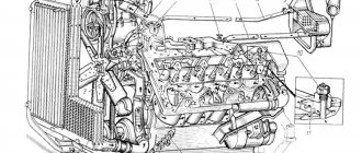
Design and principle of operation of the cylinder of the cab tilting mechanism
Currently, all cabover vehicles use double-acting MOK hydraulic cylinders with a built-in hydraulic drive throttling mechanism. The design of this device is based on a steel cylinder, closed at both ends with lids. On the cover covering the lower end of the cylinder there is an eye for hinged mounting on the side member of the car frame. Inside the cylinder there is a piston with sealing rings, the piston is connected to a steel rod, which passes through the top cover (sealing is provided by the cuff) and ends with an eye for a hinge connection with a longitudinal beam or other power element of the cabin.
In the covers of the MOK hydraulic cylinder there are fittings (or bolt fittings) for connecting pipelines. In the top cover (on the rod exit side), the fitting immediately goes into a channel through which the working fluid is supplied and discharged from the cylinder. In the bottom cover (on the side of installation on the frame) there is a throttle (throttle assembly) and/or a check valve, which limit the speed of flow of the working fluid from the cylinder when lowering the cabin. The throttle is a narrowing of the channel machined into the cover, the passage of which can be constant or varied with an adjusting screw. And the check valve (also known as a hydraulic lock) prevents leakage of working fluid from the cylinder cavity when the cab is raised.
The operating principle of the MOK hydraulic cylinder is simple. If it is necessary to raise the cabin, the pump is rotated and oil is supplied through a pipeline to the bottom cover of the cylinder, the liquid passes through the channels into the cylinder and pushes the piston - under the influence of the pressure created by the liquid, the piston moves and pushes the cabin through the rod, ensuring its overturning. If it is necessary to return the cabin to its original position, oil is supplied to the top cylinder cover, through which it enters the cylinder and pushes the piston - under the action of the created force, the piston moves down and lowers the cabin. However, a throttle is located in the lower cylinder cover, which prevents the rapid flow of oil from the cavity - this creates a force that limits the speed of lowering the cabin, thereby preventing shocks and shocks.
The speed of raising and lowering the cabin is regulated by a throttle and a check valve, for which appropriate screws (with a slotted head or a hexagon for an open-end wrench) are provided on the top cover of the MOK cylinder.
Cylinders can be divided into two groups according to the method of supplying working fluid:
- With connections of lines directly to the top and bottom covers;
- With lines connected to one cover (usually the bottom) with oil supplied to the second cover by a built-in metal tube.
The MOK cylinders of the first type are most simply designed - on both of their covers there are fittings to which pipelines (hoses) from the MOK pump are connected. Hydraulic cylinders of the second type are more complicated; both fittings are located on the bottom cover, but one fitting is connected to a steel tube through which oil flows to the top cover. Devices of the second type make it possible to reduce the length of oil lines and increase their reliability, since they are in the same plane and deform synchronously when the cabin is raised/lowered.
How to lift the body on a KamAZ
How to raise the body of a Kamaz truck is one of the most popular questions among drivers.
The dump truck body is made in the form of a rising and falling platform; it is controlled not by one button, but by a system of mechanisms.
To understand how to lift the body on a Kamaz dump truck, photo above, you need to know the structure of the platform, and how to control these devices, let’s start in order.
Construction of the KAMAZ 6520 platform
ATTENTION! A completely simple way to reduce fuel consumption has been found! Don't believe me? An auto mechanic with 15 years of experience also didn’t believe it until he tried it. And now he saves 35,000 rubles a year on gasoline! Read more"
The platform on the KAMAZ 6520 dump truck is all-metal, welded, has a protective visor, an opening tailgate and automatic tailgate locks, it is heated by exhaust gases to prevent the cargo from freezing in the cold season.
The dump truck equipment consists of a platform, a lifting and lowering mechanism and a subframe. The volume of the Kamaz platform is 12 cubic meters, and its tilting angle is 50 degrees. The subframe is a welded structure consisting of a pair of side members, a cross-shaped reinforcement and cross members.
The mechanisms for raising and lowering the KAMAZ platform consist of:
- A power take-off equipped with an oil pump is designed to take power from the gearbox;
- Gear type high pressure oil pump. It provides an oil supply of 85 l/min with a rotation speed of 1920 rpm;
- Hydraulic cylinder (one-way telescopic);
- The control unit, which serves to control the pressure of the working fluid inside the hydraulic system of the tipping mechanism, it consists of an electro-pneumatic valve and a control valve;
- The platform lift limiting valve is used to stop the platform lifting when it reaches the maximum angle;
- The oil tank is stamped in two halves; it is equipped with filters located in the filler neck and in the drain line;
- The stabilizer serves to hold the platform during unloading to avoid lateral movements
Principle of operation
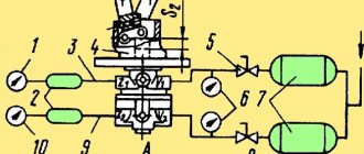
Diagram of dump mechanism components
The mechanism that lifts the platform is hydraulic.
It consists of a power take-off box (abbreviated PTO), an oil pump, a hydraulic distributor, a hydraulic cylinder, a valve that limits the rise of the platform, a pneumatic block, an oil tank with a filter and a whole system of hydraulic and pneumatic wires.
To turn on the hydraulic systems of the platform tilting mechanism, you need to turn on the clutch, then turn on the electromagnet “A” on the pneumatic block (look at the diagram of the mechanism components just above), which controls the power take-off. The air, in this case, enters the pneumatic cylinder 4, which turns on the PTO 3. As soon as the clutch is engaged, the oil pump starts working, from tank 1 the oil flows to the hydraulic distributor 7, from which it goes to drain.
To raise the platform, you need to turn on the electromagnet “B”, which controls the hydraulic distributor section.
From the pneumatic system, air enters the pneumatic cylinder 6 on the hydraulic distributor 7 and moves its spool to the left extreme position.