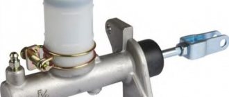
To convert the force with which the driver presses the pedal into the pressure of the working incompressible fluid located in the clutch drive, UAZ “Bukhanka” vehicles use a clutch master cylinder (MCC). Naturally, this part is not unique to UAZ vans; the GCS is installed on vehicles with a hydraulic type of clutch drive.
Let's talk about the design and functions of the GVC, possible unit malfunctions and their diagnosis.
The device of the UAZ clutch master cylinder
The main clutch for UAZ 3151, “Hanter”, Patriot with article number 420.469-1602300 has some differences, but not dramatic ones. It just has a tank installed, not a tube and an eye instead of a cylinder piston pusher fork. For “tadpoles” and “loaves” the article number is 420.3741-1602300.
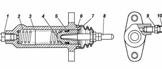
It is quite possible to replace the necessary parts and assemble what you need. How the GTZ works is shown in the figure below.
The device shows how the free play of the clutch pedal is adjusted. To do this, you need to screw in or unscrew the pusher fork.
GCS cuffs consist of a ring and a so-called “mushroom” with a diameter of 22 mm.
Operation of the GVC
Briefly, the clutch operation looks like this:
- When the clutch pedal is depressed, the pusher moves the piston and the compensation hole closes.
- It pushes fluid into the system in front of it creating pressure.
- This pressure acts on the piston of the working cylinder, which pushes the fork through the rod.
- The fork, moving the release bearing, presses on the petals of the basket and moves the pressure plate away from the clutch disc.
The valve and plate play an important role during pumping. Even if the system is not pumped, it will still fill up. It is enough to fill in the liquid and unscrew the valve on the working cylinder. It will fill the system by gravity, this also applies to the brakes.
The liquid enters the cavity in front of the piston through the compensation hole through the valve into the line. Once everything is filled, the liquid will flow out through the valve. Here, the main thing is that the rod is not extended and the compensation hole is not blocked by the cuff.
When pumping, everything is a little different.
- When the piston moves forward, valve 19 is open.
- When it goes backwards, the valve is closed and a vacuum is created at the front.
- There are holes in the piston covered by plate 3. It moves away and opens the holes. Liquid flows from the cavity above the piston and the reservoir through the bypass hole into the discharged cavity in front of the piston. The cuff (fungus) allows it to leak.
- Having reached the locking ring, the piston stops, the spring presses the fungus and the plate. This is readiness for a new cycle.
The principle of operation of the clutch on the UAZ loaf
By pressing the pedal, the driver acts on the fluid in the line. The fluid transfers pressure from the master cylinder piston to the slave cylinder piston. The master cylinder moves the fork piston.
The release fork presses against the release bearing, which transmits force to the clutch mechanism, which disengages the transmission from the transmission.
By releasing the pedal, the driver returns the entire mechanism to its original state. Under the action of the return spring, all elements involved in the process of disengaging the clutch assume their normal positions, this is how the UAZ loaf clutch works
Operation of the GVC
Below is a brief description of how the clutch works:
- When you press the clutch pedal, the pusher moves the piston and the compensation hole closes.
- It pushes fluid in front of it into the system, creating pressure.
- This pressure acts on the piston of the working cylinder, which pushes the rocker arm through the rod.
- The fork, moving the release bearing, acts on the crankcase petals, releasing the pressure plate from the clutch disc.
The valve and disc play an important role in the pumping process. Even if the system is not primed, it will still fill up. Simply unscrew the master cylinder valve and allow the fluid to flow through it. It fills the system by gravity, the same applies to the brakes.
The liquid enters through the expansion port into the cavity in front of the piston through the valve into the line. When filling is complete, the liquid flows out through the valve. The most important thing is that the piston rod should not be extended, and the expansion hole should not be blocked by the handle.
When pumping, everything happens a little differently.
- When the piston moves forward, valve 19 is open.
- When moving backwards, the valve is closed and the front valve creates a vacuum.
- There are holes in the piston that are closed by plate 3. It retracts and opens the holes. Liquid flows from the space above the piston and reservoir through the bypass hole into the space in front of the piston, which is under pressure. The collar (cork) allows it to overflow.
- When the lock ring is reached, the piston stops and the spring compresses the plunger and plate. It's ready for a new cycle.
Clutch design of the most common UAZ models
The entire clutch system UAZ loaf
First, let's define the term "clutch". It is necessary for smooth connection and disconnection of the crankshaft with the vehicle transmission. This is necessary when changing the driving mode (changing gears in the transmission) or stopping the car. The UAZ 469 military jeep was equipped with a dry single-plate clutch, a very popular system in the automotive world at that time. This coupling consisted of the following components:
- pressure disk in the housing;
- special pressure springs and clutch release levers;
- friction disc equipped with friction linings.
The general design looks like this. The so-called casing (clutch housing with all mechanisms) is bolted to the crankshaft. Alignment is established according to the factory marks on the housings. It is important to understand that when the driven and driven plates touch, a tremendous amount of friction is created to transfer torque from the crankshaft to the vehicle's transmission, which transfers it to the wheels.
The pressure plate is installed together with springs, protected from overheating by special insulating washers on the side of the pressure plate. For this reason, the basket is made of alloy and leaves ventilation holes, and the pressure plate is installed together with springs, which are protected from overheating by special heat-insulating gaskets on the side of the pressure plate.
Malfunctions
The main malfunctions of the GTZ are damage to the cuffs. If the “fungus” is damaged, the piston will not create pressure in the system and the clutch will stop squeezing. Usually these are burrs, cracks, or simply worn down. Frequent, repeated pressing will, of course, help, but not for long. It is impossible to turn on the speed and move away. It is necessary to change the cuffs or replace the entire main one.
In the second option, if the second annular cuff malfunctions, the liquid will leak out. DOT will drip onto the cab floor. It is quite possible to replace it with a ring from the repair kit.
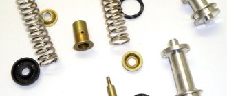
Clutch master cylinder repair kit
The quality of UAZ clutch cylinders leaves much to be desired. Some car enthusiasts converted them to VAZ cars, which are more reliable. I also refused to use repair kits, since there are no fewer problems with them. Given the low cost of repairs, the service life of the repaired GVC was from a month to six months.
To replace cuffs:
- unscrew the main fitting;
- remove the retaining ring;
- push the cuff with the piston towards the stopper;
- wipe all parts and the inside of the cylinder with a clean cloth;
- make sure his mirror is not scratched;
GCS assembly
- replace the ring cuff;
- on the stopper side, put the piston in place and install the stopper;
- on the side of the fitting, place a plate and 2 cuffs;
- insert the spring and tighten the fitting by squeezing.
Prevention
To ensure that the clutch system lasts as long as possible, monitor the level of remaining fluid in the system. After 2 years or 50 thousand kilometers, it must be drained and filled with a new one. After this procedure, be sure to bleed the system. Remember that hydraulic fluid absorbs moisture well. If replacement is delayed, rust will form in the system, which will shorten the life of the clutch master and slave cylinders. Make sure the tubes are tight, especially in the places where metal and rubber connect. It happens that the material cracks or rubs against the wheel (if we are talking about the front ones). This is very dangerous, since if the system depressurizes, you will be left without a clutch and you can only get to your destination by towing or ruining your gearbox.
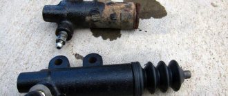
Replacing the clutch master cylinder
Prepare keys for 12 and 13, pliers and a screwdriver. Before starting replacement work, pump out any remaining DOT from the reservoir.
- loosen the clamp with a screwdriver and disconnect the tube from the tank;
- Using pliers, remove the cotter pin from the pin in the pusher fork and remove it;
- unscrew the cylinder mounting nuts;
- unscrew the line pipe;
- remove the part.
GCS piston with plate and fungus
To remove the main clutch you will have to sweat because of the inconvenience
You can unscrew the tube onto the working cylinder at the end
After replacing with a new one, do not screw the outlet tube until liquid flows out of the hole.
As you can see, replacing the cylinder yourself is quite simple. There are only difficulties with installing the pin and pinning it. Now there is a larger selection on the market, it is quite possible to choose a good quality one. When replacing, an “Expert Part” was installed and the flight was normal for 2 years. Well, in conclusion, a video on the topic:
Principle of operation
How does a clutch slave cylinder work? UAZ "Patriot" controls it using hydraulics. When you press the clutch pedal, pressure from the metal rod is applied to the piston. Next, the fluid, moving through the pipelines, activates the clutch slave cylinder. UAZ “Hunter” has aluminum lines, which are replaced with rubber lines at the connection points. Under the influence of high pressure, the rod releases the release bearing. This stops the transmission of torque from the engine to the gearbox. When the pedal is released, the clutch slave cylinder (UAZ-469 is no exception) reconnects the clutch discs. Torque transmission resumes. It is worth noting the ease of use of such a system. Compared to a cable drive, this pedal is much easier to press. The disc connects softly and smoothly. Lining wear is minimal.
The device of the UAZ clutch master cylinder
The main clutch for UAZ 3151, “Hanter”, Patriot with article number 420.469-1602300 has some differences, but not dramatic ones. It just has a tank installed, not a tube and an eye instead of a cylinder piston pusher fork. For “tadpoles” and “loaves” the article number is 420.3741-1602300.
It is quite possible to replace the necessary parts and assemble what you need. How the GTZ works is shown in the figure below.
The device shows how the free play of the clutch pedal is adjusted. To do this, you need to screw in or unscrew the pusher fork.
GCS cuffs consist of a ring and a so-called “mushroom” with a diameter of 22 mm.
Operation of the GVC
Briefly, the clutch operation looks like this:
- When the clutch pedal is depressed, the pusher moves the piston and the compensation hole closes.
- It pushes fluid into the system in front of it creating pressure.
- This pressure acts on the piston of the working cylinder, which pushes the fork through the rod.
- The fork, moving the release bearing, presses on the petals of the basket and moves the pressure plate away from the clutch disc.
The valve and plate play an important role during pumping. Even if the system is not pumped, it will still fill up. It is enough to fill in the liquid and unscrew the valve on the working cylinder. It will fill the system by gravity, this also applies to the brakes.
The liquid enters the cavity in front of the piston through the compensation hole through the valve into the line. Once everything is filled, the liquid will flow out through the valve. Here, the main thing is that the rod is not extended and the compensation hole is not blocked by the cuff.
When pumping, everything is a little different.
- When the piston moves forward, valve 19 is open.
- When it goes backwards, the valve is closed and a vacuum is created at the front.
- There are holes in the piston covered by plate 3. It moves away and opens the holes. Liquid flows from the cavity above the piston and the reservoir through the bypass hole into the discharged cavity in front of the piston. The cuff (fungus) allows it to leak.
- Having reached the locking ring, the piston stops, the spring presses the fungus and the plate. This is readiness for a new cycle.
Design
Unlike front-wheel drive foreign cars, on all-wheel drive UAZ Patriot vehicles the clutch slave cylinder (its adjustment is at the end of the article) is hydraulic and is controlled using fluid pressure, and not a cable. The design of this element includes several components. This:
- Frame. It is made of plastic or metal.
- Piston (working rod).
- A valve that releases air when the clutch system is bleeding (adjusting).
- Retaining ring.
- O-rings. Made from durable rubber.
- Return spring.
- Pusher. It affects the previous element.
Replacing the UAZ clutch disc
Removing the clutch pressure and driven discs SEQUENCE OF ACTIONS Remove the gearbox.
Removing the hydraulic clutch slave cylinder
Using a 12mm wrench, unscrew the four bolts securing the lower part of the clutch housing. One of the bolts secures the end of the ground wire to the clutch housing.
Remove the lower part of the clutch housing with the gasket.
We use a chisel to mark the relative positions of the flywheel and the clutch drive plate (“basket”).
While holding the flywheel from turning with a screwdriver or a mounting spatula, use a 12mm wrench to evenly unscrew the six bolts securing the “basket” to the flywheel. Only two “basket” mounting bolts are accessible at a time. To access the remaining bolts of the flywheel, turn it, engaging the teeth of the ring with a screwdriver.
We remove the “basket” and the driven disk.
The driven disk hub protrudes more on one side than on the other. This side should be facing the gearbox. We install the driven and driving disks on the flywheel and secure them with bolts. We do not tighten the bolts to maintain the mobility of the driven disk.
We center the clutch driven disc using a special mandrel or the gearbox input shaft. Without removing the mandrel, evenly tighten the drive disk mounting bolts to the recommended torque. We take out the mandrel and install the lower part of the clutch housing and the slave cylinder. We install the gearbox by applying CV joint-4 lubricant to the splined end of the input shaft.
DIY replacement
First you need to drain the remaining liquid in the system. This can be done using a syringe. This operation is necessary to flush out dirt from the hydraulic drive system. On some models, access may be blocked by the cooling system expansion tank. For convenience, remove the container’s fastening nuts and remove the hose. It should be unscrewed with a 10mm wrench. Next, we dismantle the metal tube that comes from the clutch master cylinder. It can be copper or aluminum. After this, we remove the main cylinder, having previously unscrewed the two fastening nuts with a 13mm wrench. Using a 17 socket, you need to remove the hose that comes from the working cylinder. Next, we will again need a 13mm wrench. Using it, we unscrew the two bolts that secure the clutch slave cylinder. The UAZ is in neutral gear. The working cylinder itself on this car is mounted on the gearbox housing. To avoid damaging other elements, carefully disconnect the pushrod from the fork. If the hoses are removed “in weight” (that is, on the removed element), the cylinder can be secured with an adjustable wrench on one side, and on the other, unscrew the tube with a cape. But be careful, as mechanical stress may cause the rubber to crack.
Malfunctions
The main malfunctions of the GTZ are damage to the cuffs. If the “fungus” is damaged, the piston will not create pressure in the system and the clutch will stop squeezing. Usually these are burrs, cracks, or simply worn down. Frequent, repeated pressing will, of course, help, but not for long. It is impossible to turn on the speed and move away. It is necessary to change the cuffs or replace the entire main one.
In the second option, if the second annular cuff malfunctions, the liquid will leak out. DOT will drip onto the cab floor. It is quite possible to replace it with a ring from the repair kit.
Signs of trouble
How do you know if your car needs to replace the clutch slave cylinder? UAZ is a very reliable car, but this part can also fail. A breakdown can be determined by several signs. Firstly, this is a sharp decrease in the liquid level in the tank. If there is a leak, the cylinder boot may have broken through. Damage may also affect rubber or aluminum tubes. Check their integrity. Secondly, the pedal stroke becomes softer. “Clutch failures” are observed. This indicates the presence of air in the system. It can only get in if there is mechanical damage to the boot or the body itself. In this case, it is necessary to repair the part or replace the entire clutch slave cylinder. In case of such a malfunction, the UAZ also changes the pedal stroke. The clutch is released and squeezed lower and lower, and the gears are very difficult to shift. Most often, in this case, a malfunction of the return spring occurs. Here it is enough to make repairs by purchasing a repair kit. It includes such elements as cuffs, rod, spring, stopper and o-ring.
Clutch master cylinder repair kit
The quality of UAZ clutch cylinders leaves much to be desired. Some car enthusiasts converted them to VAZ cars, which are more reliable. I also refused to use repair kits, since there are no fewer problems with them. Given the low cost of repairs, the service life of the repaired GVC was from a month to six months.
To replace cuffs:
- unscrew the main fitting;
- remove the retaining ring;
- push the cuff with the piston towards the stopper;
- wipe all parts and the inside of the cylinder with a clean cloth;
- make sure his mirror is not scratched;
DIY repair
So, the part has been removed and is ready for disassembly. First, unscrew the air bleed valve and remove the retaining ring. After disassembling the part, we inspect the condition of all elements - spring, piston, pusher and sealing rubber bands. They must not show any signs of mechanical damage. Next, we wash the insides of the element. There is no need to do this with aggressive liquids like gasoline and diesel fuel. Fill a medical syringe with hydraulic fluid and use pressure to clean out the dirt inside it. If the damage is only local, we need a repair kit to restore it. It is worth noting that even with one damaged part, all the entire elements are replaced, be it an elastic band, boot or spring. This will increase the service life of the working cylinder.
Frequent malfunctions and their causes
The clutch system of a UAZ vehicle is characterized by various malfunctions: the clutch is strengthened, the mechanism does not disengage, slips or does not pump. Timely maintenance, replacement of worn parts, lubrication and monitoring of the liquid level in the tank, diagnostics of all systems and components of the mechanism help to avoid such problems.
The operating instructions provide basic information about the operation of transport units, their preparation for operation, the rules and frequency of monitoring the functionality of the units, the main malfunctions and the decoding of error codes. Following the manufacturer's recommendations will extend the life of the equipment. Simple breakdowns can be fixed yourself.
For more complex system malfunctions, it is recommended to contact a service center.
The first category of reasons relates to the problem when the system cannot start completely when the pedal is lowered. The algorithm of actions is as follows:
- Lack of free play on the pedal. Repair measures consist of adjusting the shutdown drive.
- A malfunction in the pressure plate movement design requires replacement of the part or removal of the cause of the jam.
- Defective pressure springs, reduced force. Purchasing new spare parts will help correct the situation.
- Oil getting on the friction surface of the discs. It is necessary to rinse and wipe the elements dry with gasoline.
- Prolonged slippage causes overheating. The mechanism will cool down on its own after some time.
If the system starts up jerkily or with vibration, the reasons may be as follows:
- Oil getting on the friction surface of the discs. It is necessary to install a new part or wipe the old one with gasoline, remove protruding irregularities on the surface of the pressure plate and flywheel.
- Friction linings worn down to the rivets indicate the need for immediate replacement of the component.
- Incorrect placement of the pull levers. It will be necessary to dismantle the clutch and adjust the components.
If an extraneous noise occurs when you press the pedal, this may indicate that the bearing has become unusable or lacks lubrication. If using oil does not help, you will need to purchase a new element. A break in the release spring makes it impossible to lock the pedal in the upper position. The spring needs to be replaced.
Clutch disappears
Often the mechanism does not start or disappears after the vehicle has been idle for a long time. The probable cause is “sticking” of the driven disk to other structural elements. If several attempts to start the car do not lead to success, it is better to contact a service center. In this case, you will not be able to correct the situation on your own.
Drives the clutch
A common group of malfunctions is associated with a situation where the clutch is driven and there is no way to completely disengage the mechanism. There could be several reasons:
- Free play is greater than the permissible limit. An adjustment needs to be made.
- Damage to the driven disk. It is necessary to change or, if possible, correct the deformation.
- Destruction of driven disk elements. There is only one way out - to purchase a new part.
- Air entering the hydraulic piping system. Pumping the mechanism will help correct the situation.
- Hub jamming. Remove nicks, foreign elements, burrs and other causes of structural malfunction.
- Incorrect placement of the pull levers. It will be necessary to dismantle the clutch and adjust the components.
everything useful is here
Removing the clutch pressure and driven discs SEQUENCE OF ACTIONS
We remove the gearbox.
Removing the hydraulic clutch slave cylinder
Using a 12mm wrench, unscrew the four bolts securing the lower part of the clutch housing. One of the bolts secures the end of the ground wire to the clutch housing.
Remove the lower part of the clutch housing with the gasket.
We use a chisel to mark the relative positions of the flywheel and the clutch drive plate (“basket”).
While holding the flywheel from turning with a screwdriver or a mounting spatula, use a 12mm wrench to evenly unscrew the six bolts securing the “basket” to the flywheel. Only two “basket” mounting bolts are accessible at a time. To access the remaining bolts of the flywheel, turn it, engaging the teeth of the ring with a screwdriver.
We remove the “basket” and the driven disk.
The driven disk hub protrudes more on one side than on the other. This side should be facing the gearbox. We install the driven and driving disks on the flywheel and secure them with bolts. We do not tighten the bolts to maintain the mobility of the driven disk.
We center the clutch driven disc using a special mandrel or the gearbox input shaft. Without removing the mandrel, evenly tighten the drive disk mounting bolts to the recommended torque. We take out the mandrel and install the lower part of the clutch housing and the slave cylinder. We install the gearbox by applying CV joint-4 lubricant to the splined end of the input shaft.
Repair
The presence of a diagram of the internal structure of the structure allows you to carry out independent repairs in case of simple malfunctions. Increased fuel and oil consumption, coolant leakage, uncharacteristic noises and knocking in the mechanism are the first indications for repair. Maintenance and replacement of worn-out components helps prolong the functioning of parts and vehicles.
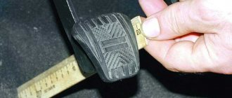
How to adjust the clutch pads
In order to adjust the clutch on a UAZ, you will need to carry out the following repair work:
- Measuring with a ruler the free radius of movement of the drive pedal that turns off the mechanism. The standard value for the spring-lever type should be within the range of 35 to 55 mm, for the diaphragm type - from 5 to 30 mm.
- Measuring the full travel of the pedal after it has been lowered to the limit. The standard value for the spring-lever type is 18.5 cm, for the diaphragm type - 16.5 cm.
- Adjust the required position by changing the position using the key.
- Controlling the distance when the pedal is lowered between the partition of the motor part and the middle of the rod axis. It is necessary to achieve a value of 9.6 cm. The fork must have a free path of movement of at least 1.7 cm. Changing the length of the work basket pusher is an adjustment tool. To do this, you need to remove and screw back the pusher until the desired value is obtained.
Adjustment of the free play of the clutch pedal is required if the distance between the rotating part located on the release levers and the adjusting screws and elements of the device does not lie within the range of 50.75-52.25 mm. The screws can be removed and put back in until the correct size is established.
The diaphragm spring connection does not require free play adjustment and does not require adjustment of the mechanism release system. The correct dimensions of the gaps and strokes are ensured by the design features.
How to bleed the clutch
Bleeding the hydraulic drive will be required if the pedal is pressed too softly and it is not possible to completely turn off the mechanism. All this indicates the presence of air in the hydraulic drive unit. Repair measures are carried out through the bypass valve in the same way as work with a hydraulic brake drive. Having an assistant will make the task easier. Sequencing:
- Adding working fluid to the master cylinder tank to the standard limit.
- Release the bypass valve head from the protective element, connect the rubber hose.
- Preparing a container with a volume of more than 0.5 liters filled with the working mixture. Place the free end of the hose into the liquid.
- Creating pressure in the resulting system with several presses on the pedal in 1-2 seconds.
- Turn the bypass valve half a turn.
Air will escape from the system into the container with liquid. When the movement of bubbles stops, you need to press the pedal and turn the valve all the way. During activities, the presence of the mixture in the master cylinder tank should be constantly monitored to avoid re-entry of air into the system.
The described procedures are performed several times until the bubbles completely disappear.
After pumping, add liquid to the tank and return the protective cap to the valve. Do not use liquid from the container into which the hose was placed for this purpose. It contains air that disappears on its own after 24 hours or after filtration.
Leveling up
After successful installation and assembly of the element, it is necessary to fill in new hydraulic fluid. The same one is used as for the brake system. After this, unscrew the air valve of the working cylinder several turns and press the clutch pedal 5-7 times. To avoid running to the salon several times, call an assistant who will bleed the system. Be careful - when you press the pedal, hydraulic fluid will flow out of the valve. Therefore, prepare the container first. This could be an ordinary mineral water bottle. To avoid leaks, use a rubber hose. Place one end on the air valve and lower the other end into the neck of the bottle. The liquid will splash at first - this is normal. With subsequent presses, the amount of air will decrease. Press the pedal until clean, bubble-free liquid comes out of the hose. This will mean that there is no more air left in the system. Screw the valve back on and put on the protective rubber cap. Due to its location, the part is constantly exposed to water, dirt and dust. To protect the valve from clogging, this rubber cap is provided. Check the level under the hood. If necessary, top up to the maximum level. During operation, maintain the level at maximum. At this stage, bleeding of the UAZ clutch slave cylinder is completed. The pedal will return to its factory stroke.