Category: UAZ
- general information
- Precautionary measures
- Relationship between motor and circuit
- Vehicle interior
Today, not a single vehicle can do without an electrical component, so the electrical circuit of the UAZ Hunter has been repeatedly modernized and refined. The result of the designers' efforts was a full-fledged product that meets European safety and quality standards. It is no coincidence that the brand received praise from fans and connoisseurs after the appearance of an updated modification of the UAZ-315195, which complies with Euro-5 standards, in 2014.
The brainchild of the Ulyanovsk plant is still popular in the market today. Most owners value the car for its reliable and trouble-free design, which pleases with its survivability and ability to overcome off-road conditions.
UAZ-315195 “Hunter”:
general information
Serial production of the UAZ “Hunter” modification began on November 19, 2003. The predecessors of the car, modifications: 3151, 31512, 31514, 31519, 3153 were produced from 1985 to 2007. The founder who laid down the principles of the all-terrain model, UAZ-469, was produced from 72 to 85. For most fans, the cessation of production of the car in 2014 was unexpected. However, a year later, the creation resumed, only the modification complied with the increased environmental standards of the Euro-5 class.
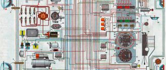
Electrical diagram of UAZ “Hunter” with fuel injection:
The wiring diagram of the UAZ Hunter is made according to the principle of one conductor, the second being the car body. Electrical circuits that control a power plant with several conductors are connected to the core only through the electronic unit. Communication with other consumers occurs through the ignition switch. The combination switch contains an interaction point and a mechanism that prevents theft. The circuit is safe because the on-board voltage does not exceed twelve volts.
The car console is equipped with devices for opening road lights and anti-fog lights. In addition, there are regulators for the operating mode of the electric fan of the stove. The following are combined into a single unit located on the switches under the steering wheel of the car: headlights, turn lamps, glass cleaners, and a cleaning fluid sprayer. Devices that consume more power are connected via electromagnet relays.
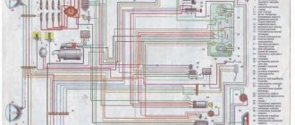
Connection diagram for motor control ZMZ-5143.10:
Precautionary measures
A UAZ Hunter car, the electrical circuit of which fails if used incorrectly, requires compliance with safety rules.
- Manipulations with the machine related to electrical equipment are carried out with the energy storage battery removed. Disabling and connecting the battery to the circuit is mandatory when the excitation is deactivated;
- Circuit monitoring is carried out without shorting the conductors to the housing; in addition, checking the serviceability of equipment using the “spark” method is prohibited, since it will lead to breakdown of some units; Only safety elements of the established type are used; Replacement of fuses is carried out with non-metal devices to avoid connecting points of the electrical circuit with different potential; You cannot remove the battery from a running power plant, this will damage the voltage regulator and other elements;
- Do not touch conductors with a high degree of electrical potential when the engine is running; Checking the diodes of the rectifying unit with an ohmmeter, as well as with a control lamp, the power supply of which is more than 12V without disconnecting the products from the generating device is excluded; Resistance to the passage of current by the insulating layer of the stator coil of the generating device is checked on a dismantled product from the machine and disconnected from the rectification unit;
- Manipulations with the welding machine on board the UAZ “Hunter” are carried out by first disconnecting the conductors from the battery, as well as disconnecting the terminals of the generating device and controller;
- When charging the battery, the product is disconnected from the vehicle.
History of the name
According to the industry norm, the new model received the index 31519, the modification is added to the index by the serial number (in this case - 5), and in the consumer market the automaker promotes the car under the name “Hunter” (from English - hunter).
Besides:
- The car is available in two bodies (all metal and with a tent roof);
- Equipped with a choice of different power units.
See also the UAZ 31514 wiring diagram.
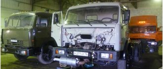
Official photo of UAZ Hunter
conclusions
We are confident that the technical features outlined in this article will help you when carrying out scheduled and repair work. Using the included color schemes, taking into account the characteristics of the car, you can properly maintain your car.
Today, not a single vehicle can do without an electrical component, so the electrical circuit of the UAZ Hunter has been repeatedly modernized and refined. The result of the designers' efforts was a full-fledged product that meets European safety and quality standards. It is no coincidence that the brand received praise from fans and connoisseurs after the appearance of an updated modification of the UAZ-315195, which complies with Euro-5 standards, in 2014.
The brainchild of the Ulyanovsk plant is still popular in the market today. Most owners value the car for its reliable and trouble-free design, which pleases with its survivability and ability to overcome off-road conditions.
Electrical circuit diagrams
18.0 Electrical diagrams
18. Electrical circuit diagrams Diagram 1. Connections of the engine control system mod. ZMZ-5143.10 Diagram 2. Connections of the engine control system mod. ZMZ-409 (Euro-2) Diagram 3. Connections of the engine control system mod. ZMZ-409 (Euro-0) Scheme 4. Electrical equipment of cars mod. 31519-095, 31519-195 Scheme 5. Electrical equipment of cars mod. 315195-025, 315195-125 Scheme 6. Electrical equipment of cars mod. 315195-023, 315195-123…
18.1 Diagram 1. Connections of the engine control system mod. ZMZ-5143.10
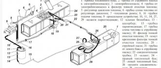
18.1. Diagram 1. Connections of the engine control system mod. ZMZ-5143.101 – electronic engine control unit; 2 – crankshaft position sensor; 3 – fuel injection pump lever position sensor; 4 – fuel stop valve; 5 – coolant temperature sensor; 6 – solenoid valve for recirculation control; 7 – connecting block; 8 – battery; 9 – diagnostic connector; 10 – fuel pump relay; 11 – electric fuel priming pump; 12 – fine filter...
18.2 Diagram 2. Connections of the engine control system mod. ZMZ-409 (Euro-2)
18.2. Diagram 2. Connections of the engine control system mod. ZMZ-409 (Euro-2)1 – battery; 2 – ignition switch (lock); 3, 29 – fuses; 4 – diagnostic block; 5 – electronic engine control unit; 6, 7, 8, 9 – fuel injectors; 10 – idle speed regulator; 11, 12 – ignition coils; 13, 14, 15, 16 – spark plugs; 17 – instrument cluster; 18 – tachometer; 19 – signal lamp; 20 – air temperature sensor in the intake pipe; 21 – temperature sensor...
18.3 Diagram 3. Connections of the engine control system mod. ZMZ-409 (Euro-0)
18.3. Diagram 3. Connections of the engine control system mod. ZMZ-409 (Euro-0)1 – battery; 2 – ignition switch (lock); 3, 31 – fuses; 4 – diagnostic block; 5 – electronic engine control unit; 6, 7, 8, 9 – fuel injectors; 10 – solenoid valve for purge of the adsorber; 11 – idle speed regulator; 12, 13, 15, 17 – spark plugs; 14, 16 – ignition coils; 18 – instrument cluster; 19 – tachometer; 20 – signal lamp; 21 – connecting deck…
18.4 Scheme 4. Electrical equipment of cars mod. 31519-095, 31519-195
18.4. Scheme 4. Electrical equipment of cars mod. 31519-095, 31519-1951 – front right lamp; 2 – right headlight; 3 – right fog lamp; 4 – sound signal; 5 – left fog lamp; 6 – left headlight; 7 – front left lamp; 8 – generator; 9 – coolant temperature sensor; 10 – emergency oil pressure sensor; 11 – oil pressure sensor; 12 – emergency coolant temperature sensor; 13 – electric washer; 14 – brake warning lamp switch...
18.5 Scheme 5. Electrical equipment of cars mod. 315195-025, 315195-125
18.5. Scheme 5. Electrical equipment of cars mod. 315195-025, 315195-1251 – right front lamp; 2 – right headlight; 3 – right fog lamp; 4 – sound signal; 5 – left fog lamp; 6 – left headlight; 7 – left front lamp; 8 – generator; 9 – coolant temperature sensor; 10 – sensor for emergency drop in oil pressure; 11 – oil pressure sensor; 12 – emergency coolant temperature sensor; 13 – electric washer; 14 – malfunction indicator lamp switch...
18.6 Scheme 6. Electrical equipment of cars mod. 315195-023, 315195-123
18.6. Scheme 6. Electrical equipment of cars mod. 315195-023, 315195-1231 – right front lamp; 2 – right headlight; 3 – left fog lamp; 4 – sound signal; 5 – right fog lamp; 6 – left headlight; 7 – left front lamp; 8 – generator; 9 – coolant temperature sensor; 10 – emergency oil pressure sensor; 11 – oil pressure sensor; 12 – emergency coolant temperature sensor; 13 – electric washer; 14 – brake malfunction warning lamp switch...
Blog about UAZ
The electrical equipment of UAZ-31519, 315195, 315148 Hunter cars is mainly made according to a single-wire circuit. The negative outputs of electricity consumers are connected to the car body and engine, which serve as the second wire. The rated voltage in the on-board network of the UAZ Hunter is 12 volts. Electrical circuit diagrams are presented below.
Electrical circuit diagrams for UAZ-31519, 315195, 315148 Hunter vehicles produced before 2007.
The electrical circuits of the engine control system are made according to a multi-wire circuit and are connected to the vehicle ground only through the electronic control unit. To switch the main circuits of the car, a combined ignition switch (lock) is used, consisting of a contact part and a mechanical anti-theft device with a lock.
The exterior lighting and fog light switches and the heater fan operating mode switch are located on the console under the instrument panel. The headlight, turn signal, windshield wiper and washer switches are combined into a block of steering column switches. High power consumers are switched on via electromagnetic relays.
Electrical equipment diagrams have the following wire color designations:
B - white; G - blue; F - yellow; Z - green; K - red; Kch - brown; O - orange; P - pink; C - gray; F - purple; Ch - black; SB - gray with white stripe; SK - gray with a red stripe; SG - gray with a blue stripe; GK - blue with a red stripe; KchB - brown with a white stripe; OG - orange with a white stripe; BG - white with a blue stripe; ZZh - green with a yellow stripe; ZK - green with a red stripe; ZCh - green with a black stripe; RG - pink with a blue stripe; RF - pink with black stripe; FB - purple with a white stripe.
Electrical diagram of a UAZ-31519 with a UMZ-4218 engine and a contactless ignition system.
Electrical diagram of UAZ-31519-095 and UAZ-31519-195.
Electrical diagram of UAZ-315195 Hunter with a ZMZ-409 Euro-2 engine and an electronic control system for fuel injection and ignition with a MIKAS-7.2 control unit.
Electrical diagram of UAZ-315148 Hunter with ZMZ-5143 engine and electronic engine control system with control unit VS-9.2 514.3763.
Electrical diagram of the UAZ-315148 Hunter engine control system with a ZMZ-5143 engine and a VS-9.2 514.3763 control unit.
Features of operating electrical equipment of the UAZ Hunter.
— Carry out any work on the vehicle’s electrical equipment only with the battery disconnected. — The battery can only be disconnected or connected when the ignition is turned off.
(-3163)
Patriot 2006. PDF (181) (GIF 500)
Patriot 2007. PDF 300)
-31638 ( -51432) PDF
Limited 2014. (3). PDF. Le Capitaine.
Limited 2014. ( 38 ). PDF. Le Capitaine.
(2008): 23602-3724010 PDF 3163-3724010-55 PDF 3163-3724020-55 PDF 3163-3724026-55 PDF 3163-3724030-55 PDF -8 3163-3724095 PDF -8 3163-3724090-20 PDF 3163-3724084- 20 PDF 3163-3724080 PDF
: 3163-6512020 PDF 3163-6512020. . PDF 3163-6512021 PDF 3163-6512021. . PDF
17.9.7 BOSH 3 (-3164) PDF
SMARTRA 3. 3163-3777001. PDF
troubleshooting
On any domestic car, problems periodically arise in the operation of electrical equipment. If you notice that the UAZ wiring is not working correctly, you need to diagnose it and check all the elements. If there are any malfunctions in the operation of electronic devices, first of all you need to check whether the fuses in the mounting block have burned out. If everything is fine with these elements, but the equipment still does not function, for example, if we talk about optics, then you need to check whether the light bulbs are working. If the lamps themselves are working, it is necessary to test the electrical part using a tester (the author of the video about testing car wiring is Ramil Abdullin).
If the Loaf refuses to start at all, you need to do the following:
- First of all, check the functionality of the battery.
- With the battery charged, use a tester to test the circuit from the coil to the generator; often the reason for the inability to start the engine is breaks in the wiring. If there are breaks, the wires should be changed. If there is oxidation on the contacts, they should be cleaned.
- Starting the power unit will be impossible if there is no spark. To diagnose the presence of a spark, remove the high-voltage cable from the spark plug and bring it to the body. When you try to start the engine, a spark should jump between the cable and the body.
- If there is no spark, the problem may be carbon deposits and deposits on it. By the way, carbon deposits are often the cause of unstable engine operation and tripping. To get rid of such a malfunction, it is advisable to clean the spark plugs; step-by-step instructions for this process are presented here.
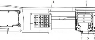
Blocks under the hood
Location
Fuse box
The power fuse block (1) consists of high power fuse links. On UAZ 315143 and UAZ 315148 cars it consists of 4 inserts, on the rest of 2.
General scheme
Purpose
Option 1
- 40A Outdoor lighting
- 90A Ignition switch terminal 30
Option 2
- 90A Ignition switch terminal 30
- 40A Outdoor lighting
- 15A Fuel filter heating
- 90/60A Glow plugs
Relay block
(2) Relays and fuses for the engine management system and fuel injection system are located here.
Additional block
Used primarily on diesel engines UAZ-315195, 315148.
Scheme
Decoding
| K1 | Starter relay |
| K2 | Main relay 2 |
| short circuit | Main relay 1 |
| K4 | Fuel heating relay |
| F1 | 30A On-board network |
| F2 | 30A On-board network |
| F3 | 25A Fuel heating relay |
| F4 | 5A Diagnostics |
| F5 | 20A Starter Relay |
| F6 | 10A Mass Air Flow Sensor |
| F7 | 5A Control unit |
| F8 | 15A Main relay 1 |
| F9 | 10A Main relay 2 |
| F10 | 25A Main relay 2 |
Relationship between motor and circuit
When releasing the car, the designers equipped the UAZ “Hunter” with three types of power plants. This move made it possible to choose a car that satisfies the needs of the consumer. However, the move used made changes to the electrical circuit of the car. Thus, the electrical circuit of the UAZ Hunter diesel is different in comparison with the gasoline unit. In addition, the electronics used on the motors have not been used before.
Motor UMZ-4213:
Install on the car:
- Electronic ignition control unit;
- Electronic filling that controls the motor;
- Sensors for reading engine indicators;
- Electronic execution mechanisms.
| Power plants used on the UAZ “Hunter” | |||
| Motor model | UMZ-4213 | ZMZ-409.10 | ZMZ-5143.10 |
| Motor type | Gasoline (injector) | Gasoline (injector) | Diesel |
| Engine volume, (l) | 2,890 | 2,693 | 2,235 |
| Motor power, (hp) | 104 | 128 | 98 |
| Cylinders, (pcs) | 4 | ||
| Camera, location | row | ||
| Chamber, section, (mm) | 100 | 95,5 | 87 |
| Displacer stroke, (mm) | 92 | 94 | 94 |
| Compression | 8,2 | 9,0 | 19,5 |
Technological solutions have made vehicle diagnostics and updates easier. It is worth noting the contribution made by the electronic system that controls the engine. The main task in the unit is performed by an electronic controller. Errors in the operation of the power plant are recorded and transmitted to the reading device in the form of a digital code.
The information is read through the diagnostic connector. Connecting the device and then deciphering the code gives an idea of where the failure occurred and how to fix the problem. Performing diagnostics involves performing manipulations.
UAZ diagnostic connector:
- The algorithm of actions is as follows:
- Set the ignition key to the “off” position;
- Remove the battery from the car for 10-15 seconds. The “self-diagnosis” mode of the controller starts;
- We connect the battery back to the car;
- We start the engine and let it run for sixty seconds;
- We connect the terminals of the diagnostic connector with a separate conductor, this activates the “self-diagnosis” mode;
Generating device Bosch 6 003 GB5011:
Confirmation of activation will be code “12” displayed three times on the reader, subsequent codes are recorded errors.
New electric current-generating devices are used to power the car and charge the battery. At the initial stage, the wiring diagram of the UAZ Hunter injector 409 engine included an “Iskra” product, the diesel engine had a “Bosch 6 003 GB5011”. Since the circuits of the generating devices are different, the connectors and conductors used under the hood of the car are also different. In the latest models, the manufacturer began to install a generating device of its own design (9422.3701). You can also read about Fuel consumption per 100 km UAZ 469.
Engine compartment
The automaker offers the following engines:
- Diesel power unit model ZMZ-5143.10 with a volume of 2.2 liters;
- Gasoline with fuel injection ZMZ-409.10 with a volume of 2.7 liters;
- Gasoline with fuel injection UMZ-4213 with a volume of 2.9 liters.
For reference: Until 2006, the model was equipped with an imported Andoria 4CT90 diesel engine, which was later abandoned in favor of domestic development. However, the electrical circuit in the engine compartment of these versions has some differences.
Under the hood there are previously uninstalled:
- Electronic ignition control unit;
- Electronic engine control system (ECM);
- Various sensors recording engine operating parameters;
- Executive electronic mechanisms.
Diagnosis of ECM faults
The basis of the ECM is an electronic controller with the following types of memory:
- PROM - programmable read only memory;
- RAM - random access memory;
- EPROM is an electrically reprogrammable read-only memory device.
For reference: thanks to such features and the self-diagnosis system, the controller remembers all deviations and errors and issues them in the form of digital codes when connecting diagnostic devices. Using the codes, it is easy to determine the cause of the failure and the electrical network component responsible for the error.
Since the price of diagnostic devices is low, many car owners independently purchase them to service their car.
The automaker recommends the following algorithm for reading service information with your own hands:
- Turn off the ignition;
- To put the electronic controller into self-diagnosis mode, you must disconnect the car from the battery for 10-15 seconds;
- Reconnect the battery;
- Start the engine and let it run for exactly 60 seconds;
- Open the diagnostic connector and connect the leads with a separate wire (No. 2 in the diagram above)
This activates the self-diagnosis mode. To confirm switching on, the signal lamp will display code 12 three times, and all subsequent ones will display faults stored in the controller’s memory.
Tip: a good help in mastering diagnostic skills will be videos from thematic forums, where owners demonstrate the features of working with testers.
Generator
In the process of improving the UAZ Hunter model, the automaker equipped the car with components and assemblies from different manufacturers. In particular, in the first batches the following was installed:
- Generator Iskra AAK 5572;
- Or a Bosch 6 003 GB5011 generator (for versions with a diesel engine).
Accordingly, they have different connectors for connection, which forced the modification of the engine compartment wiring. Currently, the automaker equips the car with its own generator 9422.3701. This feature should also be taken into account when servicing cars yourself.
Features of the modification with multifunctional control
Variations with the car body did not greatly affect its technical equipment. But when changes affected the governing bodies, they underwent modernization:
- Interior wiring for UAZ;
- Steering column control unit for turns and exterior lighting;
- Control unit for the operation of electric windshield wipers on the instrument panel.
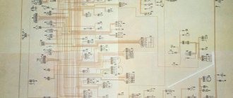
Electrical circuit diagram of a UAZ vehicle equipped with a multifunction steering column switch
Reason for modernization
Old-style instrument panel
On cars of the UAZ family, the windshield wiper control unit was located on the instrument panel. And since this did not meet safety requirements, then on all subsequent modifications:
- it was replaced with a more modern multifunctional unit located directly on the steering wheel;
- They began installing a new instrument panel.
New steering wheel switch cluster with new instrument panel
Self-upgrade
Cars of new releases already have a multifunctional control unit in the database. But owners of early editions can re-equip the car with their own hands to meet modern safety requirements.
To do this you will need:
- Original UAZ 2206 wiring - as the most suitable for self-conversion;
- Factory instruction diagram that allows you to correctly connect the steering column switches to the standard diagram;
- Desire to make high-quality installation.
Diagram of a conventional wiper control unit
The work algorithm will be as follows:
- Disconnect the battery;
- We remove the control unit from the instrument panel;
- We disconnect the wires, checking their compliance with the factory diagram in Fig. 1;
- Remove the standard switches from the steering wheel column.
To remodel, you will need to purchase several new parts:
- Block of multifunctional steering column switches from the UAZ 390995 model;
- Relay for the windshield wiper circuit (the VAZ model is best suited, as is wiring 2112, connecting the relay and the switch block);
- Contact blocks in the amount of 3 pieces (one 8-pin for the side of the steering column switches and two 6-pin for the relay and standard adapter).
New connection diagram for older versions of cars
Multi-function switch installation process
Let's start installation:
- We replace the standard connector with a new one;
- We cut the 4x4 wire (in Fig. 2 indicated by a red cross);
- We connect its ends to 31V and to the S contact of the windshield wiper relay;
- We connect wire 5-2 to pin 15 of the wiper relay;
- Contact J of the relay is connected to the 2nd contact of the steering column switch;
- We connect the 13-pin relay to ground;
- We connect the new terminal block with an adapter cable;
- We connect it to the block, which was previously connected to the standard switch on the instrument panel;
- We close the contacts of the windshield washer electric motor to contacts 6 and 7 of the switch;
- On the relay, connect pin 86 to pin 6 of the steering column switch.
Modernization scheme improved by car enthusiasts
Car enthusiasts improved the modification scheme proposed by the manufacturer, making some changes to it (in Fig. 3):
- A variable resistor R=10K was introduced into the circuit, thanks to which the pause value in the intermittent operating mode of the windshield wipers can be smoothly changed from 4 s to 15 s;
- Connect the resistor in such a way that the countdown of the operating mode begins from the moment the brush motor stops.
Conclusions: cars of the UAZ family are not only unitary multi-purpose SUVs, but also easy-to-maintain vehicles. Almost any car owner, armed with knowledge and colored electrical diagrams, is able to not only restore a failed component, but also carry out useful modernization of the car and its individual elements.
Vehicle interior
The changes also affected the interior of the car, making the modification attractive and capable of competing with cars from similar manufacturers. The upholstery, dashboard, as well as the electrical circuit of the interior have changed.
UAZ “Hunter”, instrument panel:
Changes have occurred:
- A new, informative instrument panel has been installed;
- Electric window lifts installed;
- Electrical diagram of the UAZ Hunter 315195 injector includes a relay that protects fuel injection. An electric glass and rear door wiper is installed;
- A new type of fuses are used to protect twenty-six vehicle circuits.
Internal “filling”: the next stage of evolution
Since all the main distinctive features in the engine compartment of the electrical circuits have already been described, a few words should be said about the changes inside the UAZ 315195 interior, which, by the way, are no less large-scale in their significance. The “richness” of the new model immediately catches your eye: a new electrical circuit, a UAZ wiring diagram, as well as a fuse diagram. 315195 in this part looks much preferable to the simple five-kopeck 469.
It is immediately worth noting the brand new dashboard. It has become much more informative and modern, which, of course, added “diversity” to electrical circuits.
Particular attention should be paid to the diagram of new fuses. The blade fuse block in 315195 protects 26 circuits in the SUV. For example, the following electrical circuits will be “protected” by fuses: light (low, high, side), sound signal, cigarette lighter, heater, license plate light and much more (diagram 3).
And finally, it would not be out of place to add that the electrical circuit also contains a relay unit to protect the fuel injection system. A very important thing when it comes to automotive electrical equipment.
Thus, we can say with confidence that the UAZ 315195 Hunter is a new step in the evolution of domestic SUVs. Such positive dynamics in the development of technologies and the modernization of existing developments of domestic designers, with an eye to the best European and American examples, in any case cannot but please all car enthusiasts of “native” SUVs.
The latest modernization of the Ulyanovsk Automobile Plant family of SUVs has given motorists a wonderful car – the UAZ Hunter. This is the second generation of the iconic “469” model, which has received modified components and assemblies. In particular, the power unit and electrical wiring diagram of the UAZ Hunter fully meet modern requirements for efficiency and reliability.
Characteristics
Despite its simplicity, the UAZ-469 already in those years had two fuel tanks and excellent cross-country ability. It was possible to overcome fords, obstacles and bad roads on this SUV without any modifications, but today tuning of various UAZs, including the 469 model, is becoming increasingly popular. Amateurs equip cars with larger wheels with mud tires, lift the car and install more powerful engines. True, with the latter option, all the simplicity of the design fades into the background, because you have to completely redo the entire electrical wiring of the cars. Nevertheless, the popularity of the car is only growing.
UAZ Hunter wiring diagram. Diagnosis of ECM faults. Generator Features
Did you like the article? Follow our channel for new ideas of useful car tips. Subscribe to us in Yandex.Zen. Subscribe.
The latest modernization of the Ulyanovsk Automobile Plant family of SUVs has given motorists a wonderful car – the UAZ Hunter. This is the second generation of the iconic “469” model, which has received modified components and assemblies. In particular, the power unit and electrical wiring diagram of the UAZ Hunter fully meet modern requirements for efficiency and reliability.