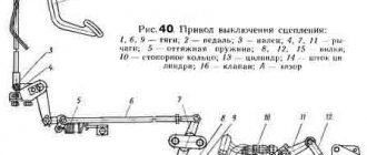
Diagram and principle of operation of the clutch release drive with a pneumatic amplifier
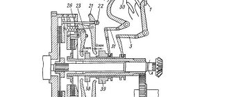
The pneumatic clutch booster serves to reduce the force on the clutch pedal when disengaging. The amplifier consists of three main parts: a source of pneumatic energy (compressor and compressed air cylinder), actuator B (Fig. 84) and a distribution device A. The amplifier body consists of two parts 5, between which a membrane is sandwiched. The amplifier housing contains hydraulic 12, pneumatic 11 and follower pistons. The working fluid from the main cylinder through tube 3 and hole 14 is brought simultaneously into the actuator cylinder? and to the end of the follower piston of the distribution device A.
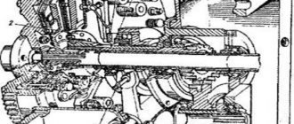
Pneumatic amplifier for the clutch drive of a KamAZ vehicle:
1 — clutch pedal; 2 - main cylinder; 3 and 4 - tubes for liquid and compressed air, respectively; 5 — parts of the pneumatic amplifier housing; 6 — pusher; 7 — return spring; 8 — clutch release lever (fork); 9 - layering; 10 — compressed air channel from the intake valve; 11 - pneumatic piston; 12 — hydraulic piston; 13 - working cylinder; 14 - hole; A - switchgear; B - actuator
When you press the clutch pedal, fluid pressure is transmitted to the hydraulic piston 12 of the actuator and the follower piston in the distribution device A, which, moving, opens the inlet valve. Through the opened inlet valve, compressed air from the cylinder enters through channel 10 under the pneumatic piston 11 of the actuator. The total force from the action of both pistons is transmitted to the pusher 6 of the clutch release fork. The fluid and air pressure is set in proportion to the force on clutch pedal 1.
When the clutch pedal is released, the intake valve closes. The pistons, under the action of springs, move back to their original position, and air from the pneumatic cylinder is released into the atmosphere.
The pneumatic clutch booster serves to reduce the force on the clutch pedal when disengaging. The amplifier consists of three main parts: a source of pneumatic energy (compressor and compressed air cylinder), actuator B (Fig. 84) and a distribution device A. The amplifier body consists of two parts 5, between which a membrane is sandwiched. The amplifier housing contains hydraulic 12, pneumatic 11 and follower pistons. The working fluid from the main cylinder through tube 3 and hole 14 is brought simultaneously into the actuator cylinder? and to the end of the follower piston of the distribution device A.
Pneumatic amplifier for the clutch drive of a KamAZ vehicle:
1 — clutch pedal; 2 - main cylinder; 3 and 4 - tubes for liquid and compressed air, respectively; 5 — parts of the pneumatic amplifier housing; 6 — pusher; 7 — return spring; 8 — clutch release lever (fork); 9 - layering; 10 — compressed air channel from the intake valve; 11 - pneumatic piston; 12 — hydraulic piston; 13 - working cylinder; 14 - hole; A - switchgear; B - actuator
When you press the clutch pedal, fluid pressure is transmitted to the hydraulic piston 12 of the actuator and the follower piston in the distribution device A, which, moving, opens the inlet valve. Through the opened inlet valve, compressed air from the cylinder enters through channel 10 under the pneumatic piston 11 of the actuator. The total force from the action of both pistons is transmitted to the pusher 6 of the clutch release fork. The fluid and air pressure is set in proportion to the force on clutch pedal 1.
When the clutch pedal is released, the intake valve closes. The pistons, under the action of springs, move back to their original position, and air from the pneumatic cylinder is released into the atmosphere.
Pneumohydraulic clutch boosters (PGU)
PGU clutches for KAMAZ, MAZ, PAZ, LiAZ, KAVZ and other vehicles
Our website presents PGU clutches for trucks and buses of domestic and foreign production.
For KAMAZ, MAZ, LiAZ, KAVZ, PAZ, Ikarus. When choosing a CCGT, take into account the make of the car, the type of gearbox, as well as the technical characteristics of the unit:
- Case dimensions;
- Operating pressure;
- Maximum piston stroke.
The pneumatic hydraulic booster does almost all the work of disengaging the clutch, while the driver, by applying force to the pedal, essentially only controls it.
When the pedal is in a free state, that is, the clutch is engaged, the amplifier rod is pressed against the seat of the mating hydraulic and pneumatic pistons. In this case, the follower mechanism pusher is in a position that corresponds to an open exhaust and closed inlet air valve.
When the driver presses the pedal (when the clutch is disengaged), the working fluid from the master cylinder enters the hydraulic cylinder, as well as to the follower pusher.
The working fluid directly pushes the hydraulic piston and at the same time transmits force to the follower pusher.
The valve of the tracking device is in position, compressed air from the receivers of the vehicle's pneumatic system is pumped into the cavity of the pneumatic cylinder and puts pressure on the pneumatic piston, moves it, and it acts on the hydraulic cylinder rod. Thus, two forces act on the rod:
- the force of the hydraulic piston, communicated by the driver himself by pressing the pedal
- the force of the pneumatic piston, which is acted upon by compressed air from the car’s pneumatic system
The PSU rod acts on the pusher, and the latter acts on the clutch fork lever. When the amplifier is operating, the follower valve is under the influence of two oppositely directed forces: on one side it is acted upon by the working fluid, and on the other by compressed air.
As soon as the driver releases the pedal, it begins to return to its original position, the working fluid stops being pumped into the piston cavity, the exhaust valve in the pneumatic cylinder is activated, through which the air leaves the above-piston cavity, the pressure drops, and return springs return all parts to their initial position. The clutch engages.
PSU repair kits
In addition to assembled, ready-to-install pneumatic hydraulic boosters, spare parts and repair kits are produced under the Hottecke brand.
Repair kit includes:
- Air valve assembly;
- Rubber O-rings, gaskets, cuffs;
- Dream remover;
- Retaining rings.
The composition of PSU repair kits may differ depending on the make and model of the vehicle. Sets of seals, wipers, and locking elements are individual for each machine.
Where to buy PGU
You can buy Hottecke pneumatic hydraulic boosters and repair kits for them in the stores of our partners.
Hottecke representative offices are open in Moscow, Yekaterinburg, Rostov-on-Don, Krasnodar and other cities of Russia.
You can also order PSU with delivery to any city in Russia in large online stores.
Clutch Inspection and Maintenance
First of all, it is worth considering what the clutch drive consists of. The design of this element includes the following parts:
- pedal;
- spring;
- main and working cylinders.
The latter is equipped with a pneumatic amplifier. Additionally, the design provides various pipes and hoses. They are used to transport working fluid. The fluid comes from the main cylinder. Through a special hose it is transferred to a pneumatic amplifier and a compensation tank.
Any actions to configure or pump the MAZ PSU require a complete inspection of the vehicle’s drive system. To do this you will need:
- Check the element for tightness. This is done by pressing the pedal about two or three times. Air leaks can be detected by ear. If the leak is weak and no extraneous sounds are heard, then it is checked visually using a soap or other solution. If a breakdown is detected, the failed elements are tightened or completely replaced.
- Check the condition of the fluid and its level inside the compensator tank. The optimal volume of liquid should be 15-20 mm below the edge of the container neck. If the level is reduced, then it is necessary to top it up to the required volume. It is important to use liquids of the same brand, otherwise problems may arise during operation.
- Check the functionality of the release springs, which are attached to the clutch pedal and the fork shaft lever. If a malfunction is detected, it must be eliminated by replacing the elements.
Additionally, during the inspection, you should check how tight the fastening bolts are, which are responsible for fixing the pneumatic amplifier, and also drain the damaged condensate that is inside the amplifier.
PGU KamAZ-5320: malfunctions
Most often, the following problems occur in the node in question:
- The compressed air flow is supplied in insufficient quantities or completely absent. The cause of the malfunction is swelling of the inlet valve of the pneumatic booster.
- Jamming of the follower piston on the pneumatic booster. Most likely, the reason lies in the deformation of the o-ring or cuff.
- There is a “failure” of the pedal, which does not allow the clutch to be completely disengaged. This problem indicates that air has entered the hydraulic drive.
KamAZ-5320, PGU: design and principle of operation
What is the KamAZ-5320 PGU device? This question interests many beginners. This abbreviation may confuse an ignorant person. In fact, the PGU is a pneumatic hydraulic power steering. Let's look at the features of this device, its operating principle and types of maintenance, including repairs.
- 1 – spherical nut with lock nut.
- 2 – piston pusher of the clutch deactivator.
- 3 – protective cover.
- 4 – clutch release piston.
- 5 – back part of the frame.
- 6 – complex seal.
- 7 – follower piston.
- 8 – bypass valve with cap.
- 9 – diaphragm.
- 10 – inlet valve.
- 11 – graduation analogue.
- 12 – pneumatic type piston.
- 13 – drain plug (for condensate).
- 14 – front part of the body.
- “A” – supply of working fluid.
- “B” – supply of compressed air.
Purpose and device
A truck is a fairly massive and large-sized vehicle. Controlling it requires remarkable physical strength and endurance. The KamAZ-5320 PGU device makes it easier to adjust the vehicle. This is a small but useful device. It makes it possible not only to simplify the driver’s work, but also increases work productivity.
The node in question consists of the following elements:
- Piston pusher and adjusting nut.
- Pneumatic and hydraulic piston.
- Spring mechanism, gearbox with cover and valve.
- Diaphragm seats, control screw.
- Bypass valve and piston follower.
Application
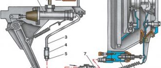
1. Compensation tank. 2. Tank cover. 3. Bolt. 4. Nut. 5,14,23. Bracket. 6. Cylinder stop. 7. Main cylinder. 8. Pedal mechanism. 9,32,37,51,54,59. Springs. 10. Brake pedal. 11. Clutch pedal stop. 12.15. Brake pedal rods. 13. Brake valve control lever. 16,24,33. Hoses. 17,19,22,31. Clutch drive pipes. 18. Triple protective valve. 20. Air cylinder. 21. Check valve. 25. Clutch fork shaft lever. 26. Rod. 27. Pneumohydraulic booster (PTU). 28. Bleeding valve. 29. Bracket thrust bolt. 30. Clutch pedal. 34,53,64. Cases. 35. Cap. 36. Control valve.
38.65. Piston. 39. Cover. 40. Wiper. 41.49. Forks. 42. Nut. 43. Guide ring. 44.66. Cuffs. 45. Exhaust window. 46.67. Retaining rings. 47,48,58,63. O-rings. 50,56,57. Traffic jams. 52. Air valve. 55. Spool. 60. Spring cup. 61. Pressure spring. 62. Underwater fitting. 68. Protective cover. 69. Pusher. 70. Ring. 71. O-ring.
B,C,D,F,K,V,M. Cavities. a. compressed air supply b. supply of working fluid
Data for monitoring and adjustments
d=0.2-0.6 mm L=185-200 mm L1=289 mm L2=30-40 mm
Leveling up
When replacing brake fluid or repairing the hydraulic part of the drive, bleed the system in the following order: - fill compensation tank 1 with brake fluid; - remove the protective cap 35, put the bleeding hose on the valve 28, unscrew the valve 1/2-3/4 turn and immerse the end of the hose in a clean, transparent container with brake fluid;
- loosen nut 4 and when the first drops of liquid appear, tighten; - sharply press the clutch pedal 30 with the valve open and slowly release with the valve closed until air bubbles stop coming out of the hose. If the release of air bubbles with liquid has stopped, tighten the bleeder valve. To prevent air from being sucked into the main cylinder when pumping, you need to ensure that the liquid level in the compensation tank is always more than half, and the end of the hose is constantly in the liquid. The criterion for complete pumping is a sharp increase in the force on the pedal when it moves by an amount of L = 35-40 mm after selecting free play.
Adjusting the clutch pedal travel
The adjustment should be carried out with the system fully bled and in the absence of compressed air in the pneumatic part of the drive in the following order:
- loosen the lock nut of the stop 11, screw it into the pedal until it stops; - move the main cylinder 7 to the upper position in the oval holes of the bracket 5; - using stop 6 and bolts 3, fix the main cylinder; -press the clutch pedal all the way to the floor;
-check the cleanliness of the clutch disengagement (the clutch should not “drive”); - if the clutch “drives,” disengage the clutch by moving the master cylinder down in increments of 1/2 turn of stop 6;
- tighten bolts 3 of the main cylinder 7 to a torque of 44-56 N.m (4.4-5.6 kgf.m); - use stop 11 to adjust the free play of the pedal, the gap between pusher 69 and piston 65 should be <1=0.2-0.6 mm, which corresponds to a pedal stroke of 1-3 mm; - with wear of the friction linings of the driven clutch disk, lever 25 turns counterclockwise, the minimum permissible size is L1 = 254 mm, if the condition of the linings is satisfactory and when the minimum size of 1L is reached, move lever 25 one slot clockwise; -measure the stroke of rod 26 at an air pressure of 800 kPa (8.1 kgf/cm2), which should be within the range L2 = 30-40 mm.
Design and operation of the clutch drive of the KamAZ-5320 vehiclePneumohydraulic clutch booster for the KAMAZ-5320 vehicle
The pneumohydraulic booster is mounted on the clutch housing (see Fig. 4.3) on the right side of the power unit.
The amplifier housing (Fig. 4.5) consists of two parts. The front (right in Fig. 4.5) part of the body 14 is made of aluminum alloy, and the rear 5 is made of cast iron. A gasket is installed between the parts of the housing, which is also the diaphragm 9 of the follower device located above the cylinder of the pneumatic amplifier.
Clutch tracking device for KamAZ-5320
The tracking device automatically changes the air pressure on the pneumatic piston 12 depending on the force of pressing the clutch pedal. The main parts of the follower device include a follower piston 7 with a sealing collar, inlet 10 and outlet 11 valves, diaphragm 9 and springs.
When the clutch pedal is released (the clutch is engaged), the pneumatic piston 12 and the clutch release piston 4 are in the extreme right (front) position (the pneumatic piston occupies this position under the action of the return spring). The pressure in the cavity in front of the piston and behind the piston corresponds to atmospheric pressure. The position of the clutch release piston 4 is determined by the stop of its pusher in the bottom of the pneumatic piston. In the tracking device, the outlet valve 11 is open and the inlet valve 10 is closed.
When you press the clutch pedal, the working fluid flows under pressure to hole A, creating pressure in the cavity of the clutch release cylinder and at the end of the follower piston 7. Under the pressure of the working fluid, the follower piston acts on the valve device in such a way that the outlet valve 11 closes, and the inlet valve 10 opens, allowing compressed air to pass through pipelines to hole B in the housing of the pneumatic-hydraulic booster. Under the pressure of compressed air, the pneumatic piston 12 moves, acting on the piston rod. As a result, a total force acts on the clutch release piston 2, ensuring complete release of the clutch when the driver presses the pedal with a force of about 200 N (20 kgf)
When the pedal is released, the pressure in front of the follower piston 7 drops, as a result, the inlet valve in the follower device closes and the outlet valve opens. Compressed air from the cavity behind the pneumatic piston is gradually released into the atmosphere, the impact of the piston on the rod is reduced and the clutch is engaged smoothly.
In the absence of compressed air in the pneumatic system, the ability to control the clutch remains, since the clutch can be released using pressure only in the hydraulic part of the amplifier. In this case, the pedal force created by the driver should be about 600 N (60 kgf).
Repair of KamAZ-5320 PGU
When troubleshooting the elements of a unit, special attention should be paid to the following points:
- Checking sealing parts. Deformations, swelling and cracks are not allowed on them. If the elasticity of the material is impaired, the element must be replaced.
- Condition of the working surfaces of the cylinders. The internal clearance of the cylinder diameter is monitored, which in fact must comply with the standard. There should be no dents or cracks on the parts.
The CCGT repair kit includes the following KamAZ spare parts:
- Protective cover for rear housing.
- Cone and diaphragm of the gearbox.
- Cuffs for pneumatic and follower piston.
- Bypass valve cap.
- Retaining and sealing rings.
Before installation, it is recommended to treat all parts with Litol type lubricant.