The specifics of Russian entrepreneurship include, among other things, independent servicing of labor items. In particular, the GAZelle wiring diagram is needed by owners precisely for this reason.
However, many of them do not understand why there are so many differences.
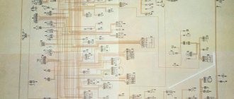
Wiring diagram for a GAZelle with a ZMZ-406 engine
Let's figure out why there are so many differences in models that are almost identical by year of production due to the electrical circuit.
Power units
The heart of any car is the engine. However, the price for it also occupies a central place in the overall cost, but that’s not the point.
When considering the chronology of the use of power units, you can see that:
- Until 2007, GAZelle was equipped with the famous ZMZ-4063 (see wiring diagram for Gazelle 406) with a volume of 2.3 liters and a power of 98 hp. With. This carburetor engine did not meet Euro-2 requirements, so the factory workers abandoned it;
- Simultaneously with it, since 2002, the injection ZMZ-40522 was installed on the factory conveyor. Naturally, both the wiring on the Gazelle and the entire ignition system were radically different from the carburetor version. In addition, it had a volume increased to 2.5 liters and a power of 143 horsepower;
- Since 2008, GAZelles began to be equipped with a new, Euro-engine from the Zavolzhsky plant, ZMZ-40524, with a capacity of 124 hp. With. It also had its own special electrical wiring (see wiring on Gazelle-405).
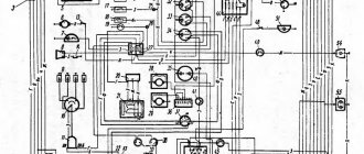
Wiring diagram - GAZelle with ZMZ 402 engine
For reference: the overwhelming majority of cars of the GAZelle family are powered by the ZMZ-40522 engine. In past years, about 150 thousand cars rolled off the assembly line annually.
Modern realities
Today, purchasing a GAZelle car is carried out using the European method:
- The buyer orders the package in advance;
- The manufacturing company will independently purchase the required chassis from the GAZ plant;
- Will install the ordered body on it;
- Equipped with the selected power unit;
- Will draw up documents for the car (PTS), including assigning your own VIN number.
Electrical wiring Gazelle Business
For reference: the length of the chassis also affects the electrical part. The plant was constantly looking for new suppliers of components, so different connectors for sensors and side lights are not uncommon on cars of the same family.
Service maintenance
It is clear that with the new power units the Gazelle’s electrical wiring has also changed:
- Injection models were equipped with more energy-intensive spark-forming elements;
- This required the use of other electronic components (a switch instead of a distributor, all kinds of sensors, an electronic unit, etc.);
- The car was equipped with a more modern generator and starter;
- New elements were added to the traditional wiring harness in the engine compartment.
Instructions for the new ignition system of the GAZelle Sobol engine
Accordingly, only official service centers, which the automaker supplied with educational photos and video materials, knew about all the changes. But private owners who serviced their cars with their own hands did not have such information.
Connection diagram of the front wiring harness GAZelle-Business
| 1 Right headlight 2 Starter 3 Battery 4 Fuse box in the engine compartment 5 Alternator 6 Left headlight 7 Windshield wiper 8 connection block to the windshield wiper wiring harness | 9 engine compartment lamp 10, 16 horn 11 windshield washer 12, 14 connections to the anti-lock brake system wiring harness 13 brake fluid level sensor 15 starter relay 17 heater valve | 18 connection block to the heater valve wiring harness 19 additional heater pump 20, 21, 22 connection block to the engine management system wiring harness 23, 24 connection block to the rear wiring harness 25, 26 connection block to the instrument panel wiring harness 27 connection block (not used ) |
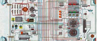
Diagram of a GAZ-2752 car with a ZMZ-4063 engine
Electrical diagram of a Sobol car with a ZMZ-4063 engine
The vehicle uses DC electrical equipment with a rated voltage of 12 V
The electrical equipment of the car is made according to a single-wire circuit - the negative terminals of sources and consumers of electricity are connected to ground, which serves as the second wire
In turn, the role of “mass” is played by the car body. Most circuits are turned on by the ignition switch.
Always on (regardless of the position of the key in the ignition switch): anti-theft system warning lamp, door locking, high beam headlight alarm, brake lights, exterior lighting, interior and individual lighting, hazard warning lights, horn and engine compartment lamp.
Diagram details : 1 – side direction indicator; 2 – direction indicator; 3 – headlight; 4 – front side light lamp; 5 – headlight lamp; 6 – switch for lights in the rear of the cabin (for a car with two rows of seats); 7 – engine compartment lamp; 8 – lights for the rear of the cabin (for vehicles with two rows of seats); 9 – canopy lighting for the front part of the cabin; 10 – lampshades (canopy lamp for GAZ-2752 with two rows of seats) of the cargo compartment of the van; 11 – starter relay; 12 – central fuse block; 13 – generator; 14 – starter; 15 – button for remote battery switch; 16 – battery switch; 17 – parking brake warning relay; 18 – ignition switch; 19 – parking brake warning switch; 20 – alarm sensor for emergency drop in brake fluid level; 21 – microprocessor ignition system fault indicator; 22 – coolant temperature indicator sensor; 23 – coolant overheat indicator sensor; 24 – oil pressure indicator sensor; 25 – emergency oil pressure indicator sensor; 26 – switch for fog light lamps; 27 – central light switch; 28 – lower fuse block; 29 – actuators of the headlight electric corrector; 30 – control unit for electric headlight corrector; 31 – windshield washer motor; 32 – sound signal; 33 – portable lamp socket; 34 – platform lamp (GAZ-2310); 35 – driver signal buzzer (GAZ-2310); 41 – instrument cluster; 42 – fuel level indicator in the tank; 43 – indicator of fuel reserve in the tank; 44 – voltmeter; 45 – speedometer; 46 – daily mileage counter; 47 – turn signal indicator (green); 48 – indicator of an emergency drop in the brake fluid level and activation of the parking brake (red); 49 – generator fault indicator; 50 – backup signaling device; 51 – coolant overheat indicator (red); 52 – side light indicator (green); 53 – high beam headlight indicator (blue); 54 – tachometer; 55 – oil pressure indicator; 56 – emergency oil pressure indicator (red); 57 – coolant temperature indicator; 58 – brake signal switch; 59 – reverse light switch; 60 – fuel level indicator sensor; 61 – switch for the electric motor of the additional heater and the electric pump for the heating system (for vans with two rows of seats); 62 – license plate lights; 63 – resistor of the additional heater electric motor; 64 – radio receiver; 65 – cigarette lighter; 66 – heater fan motor switch; 67 – electric pump for the heating system (for vans with two rows of seats); 68 – additional heater electric motor; 69 – heater electric motor; 70 – heater motor resistor; 71 – windshield wiper control relay; 72 – windshield wiper motor; 73 – wiper switch; 74 – rear light; 75 – direction indicator lamp; 76 – side light lamp; 77 – brake signal lamp; 78 – reverse lamp; 79 – fog light lamp; 36 – buzzer switch (GAZ-2310); 37 – hazard warning light switch; 38 – direction indicator relay; 39 – upper fuse block; 40 – direction indicator switch;
Self service
Very often, used GAZelle cars are purchased for business needs. And for the same reason, new owners try to do it on their own in maintaining the car in working condition.
The main problem with used cars is breakdowns and failures of the electrical part:
- Failure of incandescent lamps;
- Rotting of contacts;
- Insulation failure due to mechanical chafing or thermal effects.
Advice: The only and correct way to repair is to replace the wiring: the GAZelle receives a new one, which means that in the next 3-4 years there should be no troubles from the electrical network.
Electrical wiring for a GAZelle with an engine of the ZMZ-402 family and its modifications
Replacing the old instrument cluster with a new one
Many car owners of a gazelle or Volga car with an old-style instrument panel strive to change it to a new-style instrument panel, in which most of the indicators have been replaced with modern LED ones, and such an instrument panel looks much prettier and brighter.
So, to remove the instrument cluster, first remove the trim by unscrewing the four screws. Then remove the four screws securing the combination; disconnect the electrical connectors and remove the instrument cluster. Repair the instrument cluster by block replacement of faulty devices. To replace devices, remove the protective glass and unscrew the nuts securing the faulty device on the reverse side.
The reason why many drivers install the Gazelle Business dashboard is because it looks better. The second reason why you should buy this particular panel option is the functionality and increased number of opportunities to monitor the performance of the car.
The euro-type panel has 2 large dials - speedometer and tachometer, as well as 2 small ones, which display the amount of gasoline and the temperature of the coolant. The rest of the information about the state of the nodes and any errors that have occurred is displayed using illuminated indicators in the middle of the panel. A simpler design significantly relieves the driver’s attention.
General scheme
Modern engines are largely focused on economical operation with reference to environmental requirements.
Therefore, they differ:
- A large number of various sensors;
- Increased length of wires;
- Electronic control units for subsystems and the entire power unit;
- On-board diagnostic module (computer).
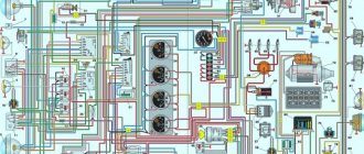
Poster from the service manual for a GAZelle with a ZMZ-40522 engine
Accordingly, the wiring diagram for the Gazelle 405 has its own characteristics, most of which relate to ensuring the correct operation of the injection system, often called the injector.
This is where, according to many diagnosticians and auto electricians, lies the weak link that affects the car engine. And one such feature will be discussed in this publication.
Electronics help
On cars with EURO 3 engines, the wiring diagram for the 405 Gazelle provides a diagnostic module.
Its frequently encountered names among motorists:
- on-board computer,
- trip computer;
- multitronics (by manufacturer's name), etc.
In addition to its basic information functions, the on-board computer is also able to inform the driver:
- Stepper motor position.
- Engine speed.
- Injection controller error codes.
- Mass air flow.
- Throttle position.
- Onboard voltage value.
Note. If a malfunction occurs in the operation of the power unit, the route PC will report errors. From their decoding, you can guess which electrical wiring diagram for the Gazelle 405 is subject to close monitoring. But he, of course, “will not say” about the true reason, but will only point out the probable reason that caused the unstable operation of a particular node.
Vehicle weight
Let's look at an example when a car stops obeying the gas pedal . The car refuses to move, when starting it keeps the speed at 2000 rpm and does not allow movement.
The trip computer often reports in such situations that there are errors:
- With throttle;
- With crankshaft sensor;
- With air flow sensor.
The example shown in the video below shows unstable operation of the power unit.
The factory instructions prescribe diagnostics using special equipment, as a result of which the owner, using a brute force method, excludes one or another node from the “suspect list”.
In fact, the reason for the failure is tritely simple - a break in the throttle ground wire , which, being screwed to the exhaust manifold stud, is subject to vibration and simply falls off (this kind of trouble happens not only with GAZ products - see the article original wiring diagram for VAZ 2112).
Please note: For better contact with the vehicle ground, the throttle electronics are powered by a separate wire - in the photo below.
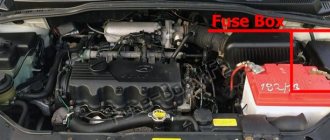
Blocks under the hood
Fuse box
It is located on the right, near the battery and consists of fuse links.
Purpose
Cars with ABS (BPR-4)
- 60A Light circuit and generator positive circuit
- 40A ABS
- 25A ABS
- 60A Common positive circuit of the vehicle, except light, generator, ABS and starter circuit
Cars without ABS (BPR-2)
- 90A Light circuit and generator positive circuit
- 60A Common positive circuit of the vehicle, except for the light, generator and starter circuits
The starter circuit is designed for high short-term current, so there is no fuse in the circuit.
Relay block
Scheme
Designation
| 1 | Main relay |
| 2 | Cooling fan electromagnetic clutch relay |
| 3 | Fuel pump relay |
| 4 | Starter relay |
The windshield wiper relay is mounted separately, above the expansion tank.
Electric panel
Old style
Scheme
Decoding
| 651.3747 | Starter relay 651.3747 |
| B116.3705 | Ignition coil B116 |
| 1412-3733 | Control unit EPXX 1412.3733 |
| 13.3734-01 | Transistor switch 13.3734-01 |
| 13.3702-01 | Voltage regulator 13.3702-01 |
| 1902.3741 | Solenoid valve (1902.3741000) |
New sample
Suitable for Chrysler 2.4L DOHC engine
Scheme
Purpose of elements
| 15 | Relay 85.3747 |
| 16 | Dryer relay 90.3747-10 |
| 17 | Relay 113.3747-10 |
| 19 | Control unit MIKAS 11CR |
We fix it ourselves
As a rule, the price of diagnostics and work by a service station technician or electrician is quite expensive. Therefore, it makes sense to check the GAZelle wiring yourself . Very often, the cause of such sudden failures is loss of contact with the vehicle's ground. Moreover, such a problem occurs in many domestic cars - the same wiring Moskvich 2141, for example.
This wire should always be kept under control. Source
When detected, such a malfunction can be repaired quite easily:
- Cut the fallen wire 5-7 centimeters below the oxidized contact;
- Clean up;
- Screw on the new contact;
- Isolate;
- Screw it to the stud, having previously cleaned the contact area with a small file.
Advice: if you have to replace the wiring yourself, then do not be too lazy when removing the old harnesses to mark on the new wiring the nodes and contacts to which it will be connected. To do this, you will need tape and paper with a pen - sign and stick handmade clues to the wiring (this advice will also help when using parts from other cars - see the article GAZelle 406 wiring diagram).
Replacing the brake drum and rear wheel pads
Using a slotted screwdriver, unscrew the three screws securing the brake drum to the hub.
We remove the drum. If it is not possible to remove the drum due to the formation of a rim on its working surface, loosen the tension of the parking brake cable or bring the shoes together (see section “7.2.5. Parking brake”).
In case of a tight fit or “sticking” of the drum to the hub, you can compress it by screwing M10 bolts into special holes. The brake drums are machined together with the hubs, so we install the removed drums only in their original places. The factory instructions recommend grinding new drums together with the hub before installing them on the car. Do not press the brake pedal after removing the brake drum.
Using a hook or thin pliers, remove the end of the tension spring from the hole in the rear block.
It is more convenient to use a special device for this. From the inside of the brake shield, with one hand we press on the cap of the rear brake pad rod, with the other hand on the cup, compressing the spring. Rotate the spring cup 90°. This will align the slot on the cup with the tip of the rod.
Remove the cups with the spring.
We remove the rod from the hole in the brake shield. Tilt the rear block down.
. remove the lower tension spring.
We remove the parking brake lever from the cable end. Remove the fastening of the front brake pad to the brake shield in the same way as the rear pad.
Remove the block, tension spring and spacer rod spring.
Using a 17mm wrench, unscrew the nut securing the rod to the block...
...and remove the parts of the parking brake adjustment mechanism.
Use pliers to unscrew the nut securing the parking brake lever.
Holding the lever mounting bolt with a 17mm wrench, use a second same wrench to unscrew the nut.
... we take out the bolt and remove the lever and the parts attaching it to the block. We rearrange the removed parts onto new pads. Install new brake pads in reverse order. We install the drum by applying CV joint grease or graphite grease to its seating belt. The brake drum is installed on the hub in only one position, since the holes for the screws are located around the circle with variable pitch. We install the wheels and press the brake pedal several times to self-install the brake components. We adjust the gap between the shoes and the brake drum (see section “7.2.5. Parking brake”). During the first 100 km, until the pads have broken in, be careful, as the car's braking distance may increase.
Gazelle wiring diagram: installation features
The small-tonnage Russian car "Gazelle" has become a reliable assistant in many areas of business. However, harsh operating conditions do not have the best effect on its components and mechanisms, especially on electrical wiring and electronic components.
And without knowledge of the principles of their work, this is not easy to do.
As in any other car, the electrical wiring on the Gazelle has many modifications that inevitably affect all internal electronic systems:
- Different body shapes provide different load capacity and other electrical wiring parameters;
- Various modifications of the power unit;
- Each engine has its own characteristics, which also affect the components of the electrical network.
In practice, this is expressed in the fact that the use of different power units inevitably entails the use of other electronic components. In particular, the Gazelle electrical wiring is installed differently for each modification.