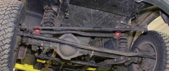
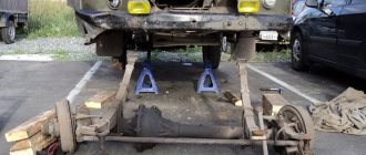
Recently a goblin has moved into my UAZ! It seems to be going well, but at low speeds it periodically begins to rock like a boat in a side wave: (The search for rocking led me to the front axle. I began to suspect that the reason for the rocking of the UAZ at a speed of 30-40 km/h were broken pin nests in the steering knuckle and loose wheels, although there was no play. I set about disassembling: unscrewing six bolts and disconnecting the hub
bent the lock washer and, using a pry bar, unscrewed both hub nuts, took out the hub along with the brake drum and wheel
Unscrewing six bolts, disconnected the hub oil deflector with axle
unscrewed two bolts on the steering knuckle housing, and without disconnecting the brake hose, disconnected and hung the brake shield assembly next to the spring
disconnected the ball joint from the transverse link
then unscrewed the remaining six bolts and separated the cover from the steering knuckle housing
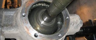
the teeth of the driven and driving gears turned out to be undamaged, which was very pleasing
To remove the knuckle housing from the support, unscrew the bolts and disconnect the sealing rings of the oil seal
unscrewed the steering knuckle lining, took out the kingpin and removed the steering knuckle housing
Christmas tree sticks BUSHES LOOKED PERFECT! then I was overcome with great surprise and at the same time disappointment from the fact that the problem was not in the pin bushings, (I was only glad that the former owner of the bridges did not deceive me, who said that the bridges had been rebuilt)
further, upset that he did not find the cause of the looseness, he decided to remove the o-rings for inspection, dismantled the steering knuckle, for which he carefully unscrewed five bolts with fine threads using the method of loosening the threads. Then he gently tapped it with a hammer, inserted the pry bar and, turning it clockwise and counterclockwise, pulled out the steering knuckle
I took it apart and took it apart))) now I’ll inspect the bearings and replace the seals, but that’s not today...damn, I’ve gotten very tired of it in two days! And what kind of fly bit the UAZ? can anyone tell me?! I will be grateful for all ideas) Good luck to everyone!
Many Internet users enter a similar request in Yandex or Google - “repair of the front axle of UAZ 469”. This means that they are interested in how to repair the front or rear axle on a UAZ themselves. Of course, the procedure for dismantling and repairing the bridge is described in special books on repair and operation, which are now not a problem to obtain. However, disassembling with your own hands both the front and rear axles down to the last screw is, to put it mildly, not an easy task. It may turn out that you just need to replace some small part, to access which you don’t have to disassemble everything.
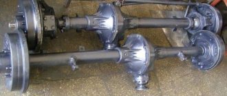
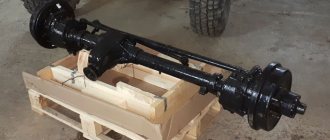
Front axle UAZ 469
Here are just some possible options for bridge failures on the UAZ 469 (Hunter, Patriot, “loaf”):
- The differential is worn out, the gear housing is bent
- Critical wear of the main gear in the gearbox
- Wear of the steering knuckle (ball joint, axle) on the front axle
- The appearance of large gaps in the pivot joints
- Bearing wear, resulting in the need for adjustment or replacement
- Injection of elements requiring lubrication
It can be difficult to understand which of the above happened to your car, however, it is often possible to roughly localize the problem even by ear. If you hear increased noise or a hum from the front or rear axle (even in neutral gear), the gearbox is most likely worn out (needs repair), or the bearings require lubrication. If your car “yaws” from side to side and the steering is fine, the problem may be stuck in the axle, CV joint, or incorrect installation of the pins that secure the ball joint, as a result of which play appears and the wheel begins to “walk.”
Front axle UAZ 469: design, diagram, repair
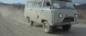
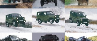
The vehicles to which the UAZ 469 belongs are designed to perform their functions in harsh conditions, difficult climatic zones, in forests, mountains, and in swampy areas without asphalt pavement. They work in the Far North, Siberia, taiga, and high mountain regions. To increase the cross-country ability of the UAZ 469, a traction axle is used at the front of the car. A vehicle with a 4x4 wheel arrangement effectively overcomes off-road areas where other vehicles cannot cope with their tasks.
Front axle UAZ 469
The driving front axle of the UAZ 469 87 is designed like the rear axle of the UAZ 469. All assembly units of the units are identical:
- stocking or crankcase;
- main gear;
- differential.
The slight difference is the thread direction of the oil deflector ring installed in the front drive gear. The carving is made right-handed. In addition, the front end of the UAZ 469B is marked with the “P” stamp. Due to their absolute identity, they are regulated, maintained, disassembled, and assembled in the same way. Also similar are all breakdowns that occur during operation.
Functional features of the unit:
- changing the trajectory of the vehicle;
- transmission, change, distribution of torque from the engine to the front wheels of the car, which results in increased cross-country ability;
- transmission to the body of shocks and resistance of wheels making contact with the road surface;
- transfer of all inertial forces arising in a moving car to the front wheels.
Despite the fact that the rear and front axles perform the same functions, the latter, in addition to traction, additionally controls the vehicle. That is why in the UAZ 469 the design of the front axle is much more complicated. The manufacturer produces several types of units.
Jeeps from Ulyanovsk are used on the country's roads with three types of bridges:
- Split design of traditional standard size. This is an old example of bridges, the common names of which are: ordinary, civil, collective farm. In fact, the correct name for the node is “Timken”. This is the name of the designer who patented the design of the unit.
- UAZ 469 bridge with final drives. Another name for it is military. In technical literature it is most often referred to as “U-shaped” or “portal”.
- Solid axle "Spicer" is a modern type front axle. It also received its name from the name of the engineer who patented this development.
How the UAZ front axle works
The diagram of the UAZ loaf front axle allows us to determine that it consists of several components:
- Composite crankcase;
- Gearbox;
- Half shafts
Below is the structure of the components of the front axle of the UAZ loaf car.
Carter
The UAZ loaf axle housing consists of 2 parts. The parts are bolted together to form a gearbox housing. Parts of the crankcase are equipped with fastenings for installing springs and shock absorbers.
IMPORTANT: As the vehicle is used, the lubricant in the crankcase heats up and expands. At the same time, the pressure in the crankcase cavity increases. To prevent leakage of the axle housing, a breathing valve is provided. It is installed on the axle housing of the UAZ front axle and is necessary to communicate the crankcase cavity with the atmosphere.
There are turning mechanisms along the edges of the bridge. They are necessary to drive a car. The mechanisms are pivotally connected to the edges of the crankcase casing. Trunnions are installed on the rotating mechanisms. They are necessary for articulated connection with the vehicle hubs. To reduce the degree of friction, the hub is mounted on roller bearings.
Gearbox
The UAZ loaf front axle gearbox consists of a main gear and a cross-axle differential. When the front axle of the UAZ loaf is turned on, the torque from the gearbox is supplied through the driveshaft to the gearbox flange. It is mounted on the same shaft with the main gear drive gear.
As the drive gear rotates, it transmits torque to the driven gear. Compared to the drive gear, it has a large diameter. This allows you to reduce the torque transmitted from the transfer case.
REFERENCE: The teeth of the gears of the main gear of the UAZ vehicle gearbox are located at an angle. This prevents the gear teeth from hitting each other, thereby reducing the noise level when the vehicle is moving.
An interwheel differential is located inside the driven gear. It consists of conical satellites and their axes. The differential mechanism includes axle shaft splines. The differential allows, when turning a car, to achieve a difference in the speed of rotation of the wheels of one axle. You can also read about UAZ 390945.
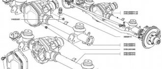
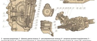
Front axle structure of UAZ 469
The design diagram of the front axle of the UAZ 469 is visible in the figure. Five bolts hold the ball joint to the axle housing. The pin bushings are pressed into it. Two kingpins secure the steering knuckle housing on top of the ball joint. The wheel reducer housing cover is secured with bolts. A trunnion with a brake shield is screwed to it using 6 bolts.
Pin stoppers prevent the pivot from turning in the steering knuckle housing. In the UAZ 469, the front axle is designed with a preload of the steering knuckle at the time of installation of the steering knuckle pins. The interference value is 0.02…0.10 mm.
Gaskets are used to adjust the UAZ 469 axle along with preload. They are installed on the top left between the trim and the steering arm housing or on the right between the steering knuckle lever. At the bottom, gaskets are placed between the linings and the steering knuckle housing. The installation drawing is shown below.
The following components and their interactions are presented here:
a - signal groove; I — right steering knuckle; II - left steering knuckle; III - clutch that disengages the wheels;
1 - oil seal; 2 — ball support; 3 — steering knuckle hinge; 4 - gasket; 5 — grease fitting; 6 — king pin; 7 — overlay; 8 — steering knuckle body; 9 — pivot bushing; 10 — ball bearing; 11 — driven shaft of the wheel reducer; 12 — hub; 13 — drive flange; 14 — movable coupling; 15 — retainer ball; 16 — protective cap; 17 — coupling bolt; 18 — axle; 19 — lock nut; 20 and 23 — support washers; 21 - drive gear; 22 — locking pin; 24 — rubber sealing ring; 25 — thrust washer; 26 — axle shaft casing; 27 - bolt limiting rotation; 28 — wheel rotation limiter; 29 — steering knuckle lever.
The lubricant is held inside the steering knuckle housing and is protected from contamination by the oil seal. It is located on top of a ball joint and consists of the following components:
- inner clip;
- rubber rings with spring 24;
- septum ring;
- sealing ring made of felt;
- outer frame.
The oil seal is pressed to the steering knuckle body with bolts. The flow of lubricant from the main gear housing to the steering knuckle is prevented by the presence of self-clamping rubber seals 1 and 3 inside the ball joint, placed in a steel cage.
Lubricant should be added to the ball joint through grease nipples 5 and 10. The pins are lubricated from above using a similar technique. The grease fittings are located on the steering knuckle arm on the right side and on the top kingpin cover on the left side. At the bottom, the kingpins are lubricated by gravity with grease coming from the ball joint.
content .. 31 32 37 ..FRONT DRIVE AXLE OF UAZ-469 CAR
The front axle of the car is driven. The crankcase, main gear and differential of the front axle do not differ from the corresponding parts and assemblies of the rear axle, with the exception of the oil slinger ring of the drive gear, which has a right-hand thread and the mark “P” (only in UAZ-469B vehicles).
All disassembly, assembly, maintenance, adjustment and possible malfunction operations are the same as for the rear axle.
The design of the steering knuckle of the front drive axle of the UAZ-469 car is shown in Fig. 71, and the UAZ-469B car in Fig. 72.
To the casing 26 (Fig. 71) and 2 (Fig. 72) of the axle shaft, a ball joint 2 and 5 with pin bushings 9 and 19 pressed into it is attached with five bolts. The steering knuckle housing 5 and 6 is mounted on the ball joint using two kingpins 6 and 9, to which the wheel gear housing cover is bolted. The trunnion 18 and 12 and the brake shield are attached to the cover with six bolts.
The steering knuckle pins are installed with a preload, the value of which is 0.02.. 0.10 mm. From turning in the steering knuckle body, the pins are locked with pins 22 and 11. Adjust the preload using spacers 4 and 20, installed at the top - between the steering knuckle lever (on the right) 29 and 1 or the pad (on the left) 7 and 5 and the steering knuckle body, at the bottom - between the linings and the steering knuckle housing of the front axle of the UAZ-469.
Rice. 71. Steering knuckle of the front axle UAZ-469: a - signal groove; I — right steering knuckle; II — left steering knuckle; III - wheel release clutch; 1 - oil seal; 2 — ball joint; 3 — steering knuckle hinge; 4 - gasket; 5 — grease nipple; 6 — kingpin; 7 — overlay; 8 — steering knuckle housing of the front axle of the UAZ-469 ; 9 — pin bushing; 10 - ball bearing; 11 — driven shaft of the wheel reducer; 12 — hub; 13 — leading flange; 14— movable coupling; 15 — retainer ball; 16 — protective cap; 17 — coupling bolt; 18 — axle; 19 — lock nut; 20 and 23 — support washers; 21 - drive gear; 22 — locking pin; 24 — rubber sealing ring; 25 — thrust washer; 26 — axle shaft casing; 27 — rotation limitation bolt; 28 — wheel rotation limiter; 29 — steering knuckle lever.
To retain the lubricant in the steering knuckle body and protect it from contamination, an oil seal is installed on the ball joint, consisting of an inner race, a rubber ring 24 and 24 with a spring, a partition ring, a felt sealing ring and an outer race. The oil seal is bolted to the steering knuckle housing. To prevent lubricant from flowing from the main gear housing to the steering knuckle, there is a self-clamping rubber seal 1 and 3 in a metal cage inside the ball joint. To lubricate the upper kingpins and add grease to the ball joint, grease fittings 5 and 10 are installed on the steering knuckle lever (right) and on the upper kingpin pad (left). The lower kingpins are lubricated with grease flowing by gravity from the ball joint.
Rice. 72. Steering knuckle of the UAZ-469B car: a - signal groove; I — right steering knuckle; II — left steering knuckle; III - wheel release clutch; 1 — steering knuckle lever; 2 — axle shaft casing; 3 - oil seal; 4 - gasket; 5 — ball joint; 6 — steering knuckle body; 7— support washer; 8 — overlay; 9 — kingpin; 10 — grease nipple; 11 — locking pin; 12 - axle; 13 — wheel hub; 14 — leading flange; 15 - movable coupling; 16— coupling bolt; 17 — retainer ball; 18 — protective cap; 19 — pin bushing; 20 - gasket; 21 — inner race; 32 — ring-partition; 23 — outer ring; 34 — rubber sealing ring; 25 — felt sealing ring; 26 — thrust washers; 27 — rotation limitation bolt; 28 — wheel rotation limiter.
A constant angular velocity joint is installed inside the steering knuckle. The design of the hinge ensures the constancy of the angular velocities of the drive and driven shafts regardless1 of the angle between them. hinge of the UAZ-469 consists of two forks, in the curved grooves of which four balls are located. In the central sockets of the forks there is a fifth ball, which is an adjustment ball and serves to center the forks. From longitudinal movement, the hinge is limited by thrust washer 25 and 26 and ball bearing 10 (Fig. 71). Internal: the driving fork of the hinge is connected by splines to the side gear of the differential, and at the end of the outer driven fork on splines only for the steering knuckle of the UAZ-469
a drive gear 21 of the wheel reducer and a roller bearing are installed, which are locked with a nut 19. Driven: the gear of the internal wheel reducer is bolted to the shaft 11, rotating in a roller bearing installed in the wheel reducer housing cover, and a bronze bushing installed inside the axle 18. At the end of shaft 11 there is a device for disconnecting the front wheels of the car, which consists of a movable coupling 14 and 15 (Fig. 71, 72), installed on the splines of the shaft and bolt 17 and 16 with a spring and a ball.
The movable coupling is connected by external splines to the internal splines of the drive flange 13 and 14, bolted to the knee hub. To reduce wear on the parts of the front axle of the UAZ-469 and save fuel when operating the vehicle on paved roads, along with turning off the front drive axle, it is advisable to turn off the front wheel hubs.
To do this, remove the protective cap 16 and 18 and, unscrewing the bolt 17 and 16 from the hole in the shaft 11 (Fig. 71), install the coupling in a position where the signal ring groove “a” on its surface is located in the same plane with the end of the flange. Having installed the coupling in the required position, screw on the protective cap. Turn on the wheel by tightening bolts 17 and 16 (Fig. 71, 72) and tightening it securely. Perform turning on and off operations simultaneously on both wheels of the front drive axle. Engaging the front axle with the wheels off is not allowed. The design of the wheel gear of the front axle of the UAZ-469 car is similar to the design of the wheel gear of the rear axle and differs from it in the installation and fastening of the drive gear and the design of the ball bearing 10 (Fig. 71), which is installed in a special cup. The drive gear is installed on the involute splines of the driven fork of the hinge and secured together with the bearings with a special nut 19, which, after tightening, is drilled into the groove of the shaft of the UAZ-469 front axle. A support washer 20 is installed between the gear and the roller bearing. The drive gear and ball bearing of the front gearboxes are not interchangeable with similar parts of the rear gearboxes. Otherwise, the front gearboxes are designed identically to the rear gearboxes and require the same maintenance. content .. 31 32 37 ..
Hinge
The constant angular velocity joint is located in the inner cavity of the steering knuckle. This mechanism corresponds to the specified angular velocities between the drive and driven shafts, which are constantly changing. It is important to keep this angle the same regardless. The front axle hinge of the UAZ-469 consists of two forks. Four balls are placed in grooves of a curved configuration.
The fifth ball is placed in the central sockets of the forks. This is an installation element, its function is to center the forks. The longitudinal movement of the hinge is limited by ball bearing 10 and thrust washers 25 and 26. The drive fork of the hinge located inside is connected by splines to the differential side gear.
At the end of the outer driven fork there is a drive gear 21 of the wheel reducer. It is mounted on splines that serve only the steering knuckle. The roller bearing is also located here. At the same time, these parts are locked with nut 19. The driven gear of the internal gearbox is bolted to shaft 11.
Repair features
Repair of UAZ front suspension
Before performing work, it is necessary to remove the front axle from the machine and disassemble it. Repair includes washing parts, assessing their condition and suitability for subsequent use. The crankcase, differential and main gear are repaired in the same way as the rear axle elements. In case of deformation of the axle housing, restoration is carried out only in a cold state.
The front axle of the UAZ 469 is dismantled in the following order.
- Chocks are installed under the rear wheels of the car.
- The brake system pipes installed on the side members are disconnected from the flexible hose connected to the wheel brakes. Unscrew and remove the nuts that secure the hoses.
- Remove the nuts holding the lower parts of the shock absorbers.
- Unscrew the bolts that connect the driveshaft to the drive gear flange.
- Disconnect the rod from the bipod and remove the nut on its ball pin.
- Unscrew the nuts securing the stepladders of the front springs, after which the linings, linings and stepladders are dismantled.
- The front part of the UAZ 469 is lifted by the frame.
If the bridge is equipped with a spring suspension, steps 1-5 are performed, after which the anti-roll bar is disconnected from the trailing arms of the suspension, and the transverse link and trailing arms are disconnected from the corresponding brackets.
Carter
UAZ 469 vehicles are equipped at the manufacturer's factory with several options for front drive axles. Accordingly, the crankcases for each model of the drive unit will be different. The crankcase is the body of the bridge. Among motorists you can still hear its other name - stocking. Gears, shafts, and axle shafts are placed inside the crankcase, thanks to which rotational motion is transmitted from the engine to the wheels.
The UAZ 469 bridge of the Timken type, civil or collective farm, is split. The housing of such a bridge consists of two halves. Casings containing axle shafts are pressed into each of them. After completing the internal contents, the housing of such a bridge is assembled into a single whole. Safety valves are also installed on the casings. They limit the increase in pressure in the oil system.
There are pin assemblies at the edges of the crankcase casings. They consist of ball joints with steering axle housings or steering knuckles on them. Inside the ball joint housings, CV joints are installed - constant velocity joints. The outer hinge pins are located in the wheel hubs. CV joint UAZ 469 collective farm bridge price on Russian markets and portals ranges from 1,500 to 3,000 rubles.
The process of disassembling the steering knuckle
Steering knuckle
The process of disassembling the front axle includes the following steps.
- Place the bridge on the stand, tighten the wheel nuts and dismantle the wheels.
- Remove the nut that secures the rod pin to the knuckle lever. Dismantle the bipod rod.
- Unscrew the screws that allow you to remove the brake drums.
- Dismantle the wheel release clutches.
- Having straightened the edges of the locking washer, twist the nut and locknut, and then remove the washer along with the inner ring and rollers of the outer bearing of the wheel hubs.
- Dismantle the hubs.
- Tighten the bolts securing the brake shields, remove the axles and shields. Remove the steering knuckle joints.
- Remove the steering linkage rod by unscrewing the nuts securing the pins.
- Tighten the bolts connecting the ball joint and the axle housing. The stops limiting the rotation of the wheels are removed, and the supports are pressed out of the casings.
- Remove the lever and the adjusting shims on the steering knuckle housing by tightening the nuts.
- Remove the nuts securing the pin pad of the adjacent knuckle on top, and then remove this pad along with the adjusting shims. Remove the lower linings along with the gaskets in the same way.
- The ball joint seal is dismantled by unscrewing the bolts.
- The pins are pressed out using a special device and the cam housing is removed.
Lubrication in the steering knuckle is required
If it becomes necessary to disassemble the steering knuckle without removing the front axle, perform the following steps:
- pads are placed under the rear wheels of the car;
- using a jack, lift the wheel on the side where disassembly will be performed;
- carry out the procedures listed in paragraphs 2-10;
- twist the nuts securing the turning lever, or the bolts securing the upper lining of the body pivot, dismantle the lining or lever, including the adjusting shims;
- remove the bottom cover in the same way;
- tighten the bolts securing the ball joint seal;
- press out the pins and dismantle the cam housing.
Steering
The steering of the UAZ 469 car is closely linked to the front drive axle, since the main components and parts are fixed to it. Steering equipment:
- Steering gear assembly with power steering.
- Cardan joint of the steering shaft.
- Steering bipod.
- Pump drive belt.
- Power steering pump with bracket, mount, bracket spacer, spacer corner.
- Oil tank with bracket and tank clamp.
- Oil filter.
- Fastening kits.
- Fan spacer with fasteners.
- Additional pulley with fasteners.
Gearbox device
The UAZ 469 gearbox for the wheels of the front drive axle is absolutely identical in design to the wheel gearbox of the rear axle. The only difference from it is the installation and fastening of the drive gear, as well as the design of the ball bearing 10, which is mounted in a special cup. The rear axle of the UAZ 469 collective farm axle has a slightly different gearbox design.
The drive gear is located on the involute splines of the driven hinge fork. It is secured together with the bearings with a special nut 19, which, after tightening, is drilled into the groove of the UAZ-469 front axle shaft. A support washer 20 is installed in the gap between the gear and the roller bearing.
The drive gear and ball bearing of the front drive axle gearboxes are not interchangeable with similar parts of the rear gearboxes. In all other respects, the front gearboxes are designed identically to the rear gearboxes and require the same maintenance and repair.
About maintenance
Repair and maintenance of the front axle of the UAZ 469 during operation requires, first of all, periodic checking and adjustment of the following parameters:
- threaded connections that need to be tightened from time to time;
- checking pivot joints for gaps;
- bearing adjustment;
- gear clutch repair;
- toe check;
- Compliance with the requirements of the lubricant table.
A visual inspection of the steering knuckles involves a thorough inspection of the components for serviceability of the adjusting bolts, wheel turn stops and checking the reliability of locking these elements. The design of the front axle provides for a maximum angle of rotation of the left and right wheels in the corresponding directions, which is 28° for UAZ 469 and 27° for UAZ 469B. A higher value of this parameter causes damage to the steering knuckle joints, making repairs much more difficult.
Patriot front strut
At the factory, the steering knuckle pins are adjusted with pretension. In this case, the same number of special gaskets is installed below and above. During operation of the bridge, special attention must be paid to the state of tightening of the pins. The tightening becomes loose as a result of wear of the rubbing surfaces. Axial gaps appear between the support rings and the ends of the pins, which must be eliminated by removing the same number of spacers in the upper and lower parts. The total thickness of the gaskets on top and bottom should be almost the same, the maximum permissible difference is 0.1 mm.
Unplanned repairs to the front axle may be required if the front wheel alignment is not properly monitored. Not only the handling and stability of the car on the road, but also the degree of tire wear largely depends on these angles. In order to check the correctness of the angles, the machine is placed on a horizontal surface. The drive front axle design provides for the following wheel alignment angles:
- longitudinal slope of the kingpins – 3°±30′;
- wheel camber – 1°30'±15'.
Values of the lateral slope angles of the kingpin:
- for UAZ 469 – 8°;
- for UAZ 469B – 5°30′.
Wheel alignment is checked depending on how worn the tires are. In order to adjust the toe, the machine is placed on a horizontal surface, the wheels are turned in the direction of forward movement. The toe-in value, shown in the photo as the difference between distances A and B, can range from 1.5 to 3 mm. To check and adjust the horizontal toe, it is necessary to loosen the lock nuts with left and right threads, and then change the length of the steering tie rod.
Connection diagram
Shaft 11 rotates in a roller bearing, which is installed in the wheel gear housing cover, and a bronze bushing located inside the axle 18. At the end of shaft 11 there is a mechanism that disables the front wheels of the machine. The device consists of movable couplings 14 and 15. They are located on the splines of the shaft and bolt 17 and 16 with a spring and a ball.
These movable couplings, with their external splines, are connected to the internal splines of the drive flanges 13 and 14, which are bolted to the wheel hubs. In order to reduce wear on the metal surfaces of the parts of the front axle of the UAZ 469, as well as to save fuel when driving on paved roads, it is recommended to also turn off the front wheel hubs while disabling the front drive axle.
To carry out such a shutdown, it is necessary to remove the protective caps 16 and 18. Next, unscrew the bolts 16 and 17 from the shaft hole 11. Place the coupling in such a position that the signal ring groove “a” on its plane is in the same plane as the end of the flange. When the coupling is installed in the required position, the protective caps must be tightened.
By screwing in bolts 16 and 17, you need to turn on the wheels. The bolts should be tightened securely. Disabling and engaging must be carried out on two wheels of the front drive axle simultaneously. It is not allowed to engage the front axle with the wheels off!
Connection diagram for the front axle UAZ loaf
Some car owners are wondering how the front axle on a UAZ loaf is engaged? The front axle is engaged in two ways:
- A lever installed in the cab. The lever controls the transfer case. When the front axle of the UAZ loaf is turned on using a lever installed in the cabin, torque from the transfer case is transmitted along the driveshaft to the drive axle.
- Using couplings installed in wheel mechanisms. It is possible to disconnect the drive axle hub from the axle shaft. Switching the UAZ Bukhanka front axle on and off using clutches allows you to reduce the load on the gearbox when driving on hard surfaces.
IMPORTANT: after disconnecting the clutches located in the wheel mechanisms, connecting all-wheel drive using a lever from the passenger compartment will be impossible.
To engage the clutch, it is necessary to remove the protective cover of the drive axle hub. Using a hexagon, screw the coupling cap until it stops. The axle shaft splines will engage and the hub will be connected to the gearbox. To disengage the clutch, perform the procedure in reverse order.
To connect all-wheel drive using a lever installed in the passenger compartment, it is necessary to do the following:
- Disengage the clutch;
- Set the gearshift lever to neutral position;
- Move the control lever to the extreme forward position;
- After completing the steps, all-wheel drive will be turned on. All-wheel drive must be turned off by moving the lever to the rearmost position.
ATTENTION: Before disabling or engaging the front axle on a UAZ loaf, you must disengage the clutch. To do this, depress the clutch pedal located in the cabin.
Maintenance
Maintenance allows you to maintain the front drive axle of the vehicle in working condition. Thanks to maintenance, the wear rate of parts and components is reduced. It is important that when it is carried out, the occurrence of malfunctions is prevented; they are identified at an early stage for timely elimination.
- daily – EO;
- first – TO-1;
- second – TO-2;
- seasonal – CO.
The frequency of maintenance-1 and maintenance-2 is regulated by GOST 21624-81.
| Operating Condition Categories | Maintenance frequency, km | |
| TO-1 | TO-2 | |
| I | 4000 | 16000 |
| II | 3600 | 14000 |
| III | 3200 | 12000 |
| IV | 2800 | 11200 |
| V | 2400 | 9600 |
Differences between military bridges and civilian ones
Military and civilian bridges differ in that the design of the former includes not only the main gear, but also wheel final drives. The UAZ 469 gearbox increases the torque received by each wheel, because of this, a vehicle with a military axle has much better maneuverability on rough terrain and in difficult off-road conditions.
A significant advantage of this arrangement is that the axis of a military vehicle axle with final drives is 4 cm higher than the axis of a civilian vehicle. Due to this, the vehicle's ground clearance is located significantly more advantageously when overcoming road obstacles. At the same time, military bridges are manufactured with a total gear ratio that is significantly greater than that of all other designs. This is what achieves a significant increase in torque. A car with similar characteristics is somewhat inferior to its analogues in terms of speed indicators.
The engine, constantly operating at high crankshaft speeds, exhausts its service life much faster. The gear ratio of old-style civil-type bridges is 4.625 or 5.125. This depends on the number of teeth of the main drive driven gear.
In military axles, the gear ratio is 5.38. For the main gear it is 2.77, for final drives it is 1.94. For Spicer type axles the gear ratio is 4.111. This applies to carburetor cars. The gear ratio of cars with a diesel engine is 4.625.
On any bridges, forced or automatic differential locking is installed on UAZ 469 civil bridges. The locking drive is used in a variety of ways:
- pneumatic;
- electric;
- mechanical.
When installing a pneumatic drive, the car is retrofitted with a pneumatic system of the simplest design. In addition to blocking the UAZ 469 on civilian bridges, it can solve many related problems.
Different bridges in the UAZ 469 differ in track width. Civilian and military bridges were previously produced with a width of 1443-1445 mm. Now the plant produces units up to 1600 mm wide. Mainly, this is a modern Spicer design. The weight of the UAZ 469 collective farm bridge is 120 kg, and the military bridge is 140 kg.
Source
Repair of bridges on UAZ 469
Many Internet users enter a similar request in Yandex or Google - “repair of the front axle of UAZ 469”. This means that they are interested in how to repair the front or rear axle on a UAZ themselves. Of course, the procedure for dismantling and repairing the bridge is described in special books on repair and operation, which are now not a problem to obtain. However, disassembling with your own hands both the front and rear axles down to the last screw is, to put it mildly, not an easy task. It may turn out that you just need to replace some small part, to access which you don’t have to disassemble everything.
Front axle UAZ 469
Here are just some possible options for bridge failures on the UAZ 469 (Hunter, Patriot, “loaf”):
- The differential is worn out, the gear housing is bent
- Critical wear of the main gear in the gearbox
- Wear of the steering knuckle (ball joint, axle) on the front axle
- The appearance of large gaps in the pivot joints
- Bearing wear, resulting in the need for adjustment/replacement
- Injection of elements requiring lubrication
It can be difficult to understand which of the above happened to your car, however, it is often possible to roughly localize the problem even by ear. If you hear increased noise or a hum from the front or rear axle (even in neutral gear), the gearbox is most likely worn out (needs repair), or the bearings require lubrication. If your car “yaws” from side to side and the steering is fine, the problem may be stuck in the axle, CV joint, or incorrect installation of the pins that secure the ball joint, as a result of which play appears and the wheel begins to “walk.”
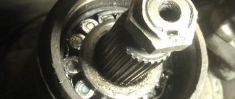
What does a CV joint consist of?
A very common malfunction is the flyout of the ball bearings that are located in the CV joint. They fly out precisely because of incorrect adjustment of the pins, as a result of which the geometric center of the CV joint and the axle do not coincide. As a result, the axle shaft “walks” in the seat and gradually breaks down. The CV joint itself is also damaged. And when turning, you can hear a crunching sound from the side of the wheel and the wheel may jam. During the repair process, some craftsmen simply throw out all the balls, except for the centering one (additionally welding it) - in order to get rid of the problem of their constant flying out.
Steering knuckle of the front axle UAZ 469 assembled
But this does not save for long; there are even cases when the welded ball breaks off while driving, the loads there are so high. It is much more effective to adjust the king pins. It is necessary to achieve a condition in which the line passing through the king pins and the center of the axle shaft intersect at one point. And it is at this point that the center of the CV joint should be located. The displacement of the axle shaft from left to right, as shown in the figure, is unacceptable; it must be rigidly fixed; for this purpose, thrust rings and bushings are provided in the design.
Space for bushing
Adjustment
Before you start adjusting, prepare everything you need: bushings for the axle (if there is a groove on the axle), 4 thrust bushings, as well as oil seals. The main condition for adjustment is that the two halves of the CV joint do not dangle, both during straight-line movement and when turning! The procedure is as follows:
- Take the ball joint and press the bushing into it so that half of the CV joint does not hang out in the ball joint.
- There is a thrust washer on top; be sure to install a new one, even if the old one appears to be in good condition.
- Take a metal shaft (you can make it from a valve, for example) with cones on both sides and put a washer on it with a diameter similar to the central ball, that is, 27 mm. Place one edge against the center of the kingpin. Ideally, the second edge should also be in the center of the kingpin. If this is not the case, place the adjusting washers in the same place where the thrust washers are, or rather, under it.
Adjustment
- It is necessary to try on the steering knuckle body over the ball joint and make sure that the center of the large hole in the steering knuckle coincides with the center of the support. If it is shifted by at least 3 mm, the CV joint cannot be assembled, since there is already a bushing there. And to adjust in the center, place a certain number of adjusting washers under the left or right kingpin, depending on which direction and how many mm you need to move the central axis.
- The kingpin must be tightened so that by hand you can turn the ball joint back and forth. If the seat for the king pin is broken and the king pin rotates together with the ball, grind off a few millimeters on the king pin and install it through the bushing. Rotation or play is unacceptable, since they lead to rapid wear of both the kingpin and the seat under it.
- It is better to replace the bushing in the axle itself (both front and rear). If necessary, adjust the size using a reamer. It is important to note that each half of the CV joint needs to be done differently. There shouldn’t be any play, but if half of the CV joint is too tight, then it’s better to remove it with a larger reamer.
- It is extremely important that the bushings are in place as shown in the image. If you place the bushing on only one side, then when the wheel turns, most of the load will fall on it, as a result - rapid wear, the appearance of play, and then the CV joint needs to be replaced.