If the car engine overheats, the unit may fail. Of course, the pistons in the cylinders can become completely jammed only if there is no coolant in the jacket, but even the boiling of antifreeze has a negative impact on the service life of the main parts of the diesel engine.
The switch-on sensor for the KAMAZ cooling system fan works “advance”, so when a dangerous level of temperature rise is reached, the contacts of the device close and the vehicle engine begins to be forcibly cooled. More details about the device, operating principle and self-diagnosis capabilities will be discussed in this article.
How to remove the electric fan drive on a KAMAZ
Solder a leaking radiator and replace the electric fan drive on a Euro KAMAZ.More
Electromagnetic fan drive of the Kamaz engine instead of a fluid coupling. Victor IlyushkinMore details
The bearing on the Kamaz electric coupling is jammed. Repair.More details
Replacing the electric coupling bearingRead more
Kamaz euro 3#electric coupling of the cooling system fan has failed#quick repairRead more
ELECTRIC CLUTCH OF FAN KAMAZ EURO 2. FORCED OPERATION MODE. KAMAZ 65115 REPAIR.More details
Electric coupling KamaZ.v.8 Nerves) 2More details
Replacing the bearing of the KAMAZ 43118 electric couplingMore details
Electromagnetic coupling KamAZ Euro 2More
Sound (roar) in the area of the Kamaz Euro 2 electric couplingRead more
Kamaz 65116. Electric viscous coupling, how to fix the problem!! Read more
Kamaz bearing replacement on an electric clutchRead more
Where is the fan switch on KAMAZ 65115 2020More details
KAMAZ. connecting an engine cooling fan. one way. Read more
Kamaz is seething with problems and solutions.Read more
Removing the viscous coupling from a KAMAZ 43118 vehicleMore details
Removal and installation of hydraulic coupling (viscous coupling) Cummins isf 3.8 | Fluid coupling fan cummins3.8Read more
KAMAZ 6520 YEAR 14 AND A LITTLE ABOUT ELECTRIC CLUTCHRead more
Source
Features of the KAMAZ cooling system
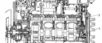
KAMAZ trucks have diesel engines that are equipped with a dual-circuit cooling system. It includes: a water pump, a radiator and a KAMAZ engine cooling fan , a pipeline system, as well as several sensors.
Unlike the cooling system of a light car, KAMAZ has 2 thermostats. This feature is associated with the structure of the engine, which is a V-shaped eight with two cylinder heads.
Another distinctive feature of KAMAZ is the presence of shutters on the radiator. In winter they are closed, so the engine warms up faster. But in the summer, the radiator does not always work smoothly. On hot days, the removal of excess heat worsens, which often leads to overheating. This problem is solved by a fan that directs air flow to the radiator, thereby dissipating excess heat. KAMAZ EURO-4 without .
How to remove the KAMAZ Euro 4 fan drive
The fan is an important part of a car's cooling system, without which the vehicle would not function effectively.
Heavy-duty machines experience heavy loads during continuous operation, so servicing the cooling system plays an important role. To repair a KAMAZ fan or replace a damaged spare part, you need to perform a number of typical actions. A service station will help you remove the fan on a KAMAZ. The wizards work according to the following algorithm:
- Remove the fastening elements and dismantle the fan impeller.
- The next step is to loosen all fastenings of the generator and pneumatic compressor belt tensioning devices. The belts are removed from the drive pulley of the unit.
- The technician removes the wires through which the signal is sent to the solenoid valve and removes the oil supply tube. The valve is removed along with the gasket and ventilation actuator.
- Next, after removing the mounts, the fan itself is removed from the engine. The procedure is carried out carefully and with great attention to spare parts.
- The next step is to dismantle the ventilation drive cover along with the driven shaft and hub. In this case, the shaft is disassembled, and the pressure ring, piston and discs are removed from it.
- The technician places the drive gear in a static position and presses it off the drive shaft.
- Then the drive shaft is pressed out, the drive housing, rear bearing, spacer sleeve, silent blocks and rear bearing race are removed.
- The mounting screws, the compressor drive and generator pulley, as well as the scoop tube are dismantled.
- At the final stage of work, the fasteners are removed, the outer spacer sleeve and the outer race of the rear bearing are pressed out. The technician removes the bearing from the fan housing and carries out maintenance of spare parts or replaces the unit with a new one.
Service specialists will carry out diagnostic procedures, repair and replacement of any parts of the cooling system for any model of KAMAZ vehicles. All services require the provision of a guarantee, the use of high-quality original or analogue parts and an objective assessment of faults.
Source
How to remove the KAMAZ Euro 4 fan drive
The fan clutch must be removed and replaced with a quality part if breakdowns and deficiencies in the functioning of the mechanism are detected.
The most common malfunction of this mechanism is the detachment of synthetic elements from the metal base and the diagnosis of ruptures. Worn splines are a common failure. Dismantling the KAMAZ electromagnetic clutch is accompanied by the removal of the radiator casing, which protects the mechanism from damage. Then the master dismantles the shaft mount, retracting the tendril that interacts with the washer. Despite the simple workflow for dismantling the electromagnetic clutch and replacing it, leave the procedure to an experienced mechanic. The technician will eliminate the consumable coolant, remove the fan and radiator drive belt and dismantle all the fixing elements, freeing the shaft and coupling.
The specialist also removes the timing cover to ensure easy removal of the coupling from the axle equipped with bearings. The retaining ring is finally removed. If any part defects are detected, repairs and service are carried out. If the breakdown is serious, the entire mechanism is replaced. In accordance with the wishes of the manufacturer, specific analog or original spare parts are used.
Subsequently, a procedure is carried out to install the coupling in its usual place. Due to the fact that each KAMAZ vehicle model has structural features, experts pay attention to the specific design of products. Although the electromagnetic clutch is not included in the list of devices considered technically complex, it is worth leaving the procedure for its dismantling to specialists. For service maintenance of KAMAZ trucks, contact the Alfa-Auto station.
Fluid coupling KamAZ 740. Diagram. Malfunctions. Repair.
A hydraulic coupling (abbreviated as hydraulic coupling) is installed on the engine of KamAZ vehicles to drive a fan to cool the liquid passing through the radiator. The fan is turned on and off using a fluid coupling depending on the temperature in the engine cooling system. If problems arise during operation, you will need to diagnose the cause and eliminate the malfunction by repairing the fluid coupling or replacing this part. If the exact cause of failure cannot be determined by external signs, then it is necessary to resort to dismantling and disassembly. What elements it consists of, how it works and how to diagnose and repair a hydraulic coupling failure - read in this article.
Where can I buy
Spare parts and other products for the car are easily available for purchase at auto stores in your city. But there is another option that has recently received significant improvements. You no longer need to wait a long time for a parcel from China: the AliExpress online store now offers the opportunity to ship from transshipment warehouses located in various countries. For example, when ordering, you can specify the “Delivery from the Russian Federation” option.
Follow the links and choose:
| Universal 85-ON Radiator Fan Switch for Kawasaki | Professional Automatic Tools Cylinder Compression Test Kit | Vdiagtool endoscope camera, IP67, for car inspection |
| 17 pcs. set for measuring pressure in the compression cylinder of a diesel engine | Injector cleaning machine for engine cleaning AUTOOL C80 | 5pcs Camshaft Fixing Tool Set |
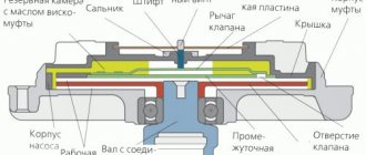
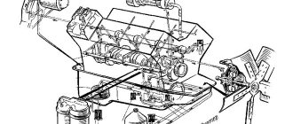
Diagram of the hydraulic coupling of the KamAZ 740 engine fan drive
- thermal power sensor mounting nut
- thermal power sensor assembly
- adjusting washer
- switch housing assembly
- fluid coupling switch spool
- return spring washer
- return spring
- switch housing o-ring
- switch housing cover
- faucet plug cover
- faucet plug lever retainer
- retainer spring
- valve plug lever
- spring washer
- cover bolt
- lever mounting pin
- faucet plug o-ring
- switch tap plug
- front cylinder block cover assembly
- hydraulic coupling drive wheel (740-1318032) Has 33 blades. The wheel is connected to the crankshaft through the splined part of the power take-off shaft. Such a wheel mechanism is inextricably linked with a driven shaft, which drives the cooling fan of the power unit system. Therefore, you can most often purchase a wheel complete with a shaft. Catalog number - 740.1318044
- screw
- lock washer
- hydraulic coupling driven wheel (740.1318046) Has 32 blades
- bolt securing the drive wheel to the casing
- hydraulic coupling drive shaft with casing assembly
- fluid coupling bearing housing
- bearing housing tube
- indicator for setting the fuel injection advance angle
- spring washer
- bearing housing mounting screw
- bearing ring
- bearing ring
- drive shaft ball bearing
- drive shaft o-ring
- drive shaft limiting washer
- limit washer retaining ring
- ball bearing rear driven shaft
- flat washer for the driven wheel mounting bolt
- lock washer
- driven shaft mounting bolt
- hydraulic coupling driven wheel shaft
- generator drive shaft ball bearing
- generator drive pulley shaft
- spring thrust ring
- generator drive pulley shaft cuff
- ball bearing front driven shaft
- generator pulley gasket
- generator drive pulley
- driven shaft cuff with spring
- spring washer
- pulley bolt
- cuff sleeve
- fan impeller hub
- lock washer
- low hub fastening nut
Types and functional features
There are several types of couplings: elastic, electromagnetic, friction, hydraulic, viscous couplings. Each variety has its own functional characteristics.
- For example, an elastic one transmits torque using two contacting rubber discs, so when the engine mode changes, the force impact falls on the soft rubber. This type is considered obsolete, so it can only be found on old KamAZ trucks. Modern models have other design solutions. The operation of the coupling is carried out thanks to two disks: the inner diameter of the driver has mounting teeth, which are secured to the shaft, the driven one has threaded bushings for seating the fan.
- The friction one has a more modern structure: it is turned on and off by a drive that responds to information from the temperature sensor. Temperature 80 degrees - turn off the fan, 90 degrees - turn on. This type is considered more technologically advanced, so friction clutches can be found on a fairly large number of trucks. By working directly with temperature, the information transmitted to the fan is considered more reliable than the forceful operation of the rubber parts of the mechanism. The system has a driven disk, a drive disk, a pressure disk, a diaphragm spring, and a drive that increases or decreases the air pressure inside the system.
- The fluid coupling operates more smoothly, reacting more sensitively to changes in the temperature coefficient. The data that the sensor reads is the coolant temperature. Passing through the entire system node, the temperature of the liquid is analyzed by the system, after which the data is transmitted to the fan unit, starting or shutting it down. The switch cylinder contains a substance that reaches the melting point, moves the spool, and opens the oil access channel. More oil means more fan speeds, which means faster rotation. After the temperature decreases and the channel closes, the rotation stops. The fluid coupling consists of a splined drive shaft, a drive wheel, a casing, and a pulley with its own shaft. The driven part includes the fan mounting hub. The speed of rotation of the wheel is directly proportional to the amount of oil entering the working cavity.
- A viscous coupling is essentially a variation of the hydro-type. Only the basis of the work is to use the viscosity of the oil. Cold engine operation causes the antifreeze fluid to move in a small circle, so the clutch rotor is in a closed state. Centrifugal forces force the oil to drain into the reserve cavities; accordingly, the oil does not push the spool, and the rotation speed drops. When the temperature rises, the antifreeze moves in a large circle, so the liquid gets inside the radiator. The air inside the radiator heats up, the bimetallic plate also heats up and bends, opening one access valve. After the valve opens, oil enters and the speed increases. If the temperature continues to rise, the bimetallic spring opens the second valve. Having a viscous consistency, the oil can maintain a certain operating temperature, preventing engine overheating. That is why silicone is most often used, characterized by high viscosity, which increases with temperature. The internal structure of this type is very similar to a fluid coupling, however, it has its own design features. For example, the presence of a rotor. The rotor shaft is attached by two bearings to the water pump; the two rotor chambers are further divided by two plastic plates, thus creating as many as four cavities.
- The electromagnetic type (electric couplings) is used on modern KamAZ vehicles. Reaching a temperature of up to 90-95 degrees, the coolant affects the sensor, which supplies power to the electromagnet. The electromagnet is activated and the metal ring is magnetized to the pulley. This process starts the fan. A lowered liquid temperature to 70-75 degrees helps reduce fan speed. Kamaz trucks have one or two fans (single-speed for older models, two-speed for newer truck models). The mechanism is also equipped with several types of relays: low speed, high speed, high antifreeze pressure, temperature sensor, crankshaft rotation sensor. The electronic control unit collects all information, analyzes, optimizes, and transmits it to the central control unit.
Today, electric fans with electronic control are the most popular. The temperature is regulated by sensors that provide information to the central electronic unit. Modern computerized systems work more smoothly, preventing the liquid from overheating.
Fluid coupling switch
- switch housing cover
- switch housing
- return spring washer
- return spring
- fluid coupling switch spool
- O-ring of the switch housing cover
- faucet plug o-ring
- switch tap plug
- pin
- valve plug lever
- retainer spring
- faucet plug lever retainer
- faucet plug cover
- shims
- thermal power sensor mounting nut
- thermal power sensor
- thermosil seal ring
Fan drive operating modes
There are three operating modes of the fluid coupling. Changing the mode is achieved by changing the position of the switch flag. The positions are indicated in the image below, and the operating modes are also described.
- Auto mode. The coolant temperature in the engine is maintained at 80-95 degrees. The hydraulic coupling switch valve is set to position B (mark on the switch body)
- The fan is turned off. The hydraulic coupling switch valve is set to position O. In this case, the fan can rotate at a low speed.
- The fan is constantly on. (locked) Operation in this mode is allowed only in emergency cases in case of malfunctions for operation in automatic mode. Operating the fan for a long time without turning it off can lead to wear and tear of the impeller. To enable this mode (if necessary), you will need to loosen the locknuts of two special bolts securing the impeller to the hub and screw the bolts so that they fit into the hole on the fan drive pulley. Retighten the nuts. When returning to automatic mode, unscrew the bolts and lock them in such a position to ensure free rotation of the fan relative to the pulley and reliable fastening of the impeller to the hub.
Cooling System Maintenance
The KAMAZ engine will work smoothly if the temperature regime is observed. Engine overheating affects its power and fuel consumption.
To prevent breakdowns, it is necessary to regularly carry out maintenance of the cooling system:
- Monitor the temperature of the liquid.
- Regularly check the structure for leaks.
- If a temperature violation occurs, monitor the condition of the thermostats and fluid coupling.
- Check the coolant level daily.
It is advisable to tighten the radiator mounting bolts every season, and also replace the old fluid with new one. In summer, blow with compressed air or flush the radiator core.
The principle of operation of the KamAZ fluid coupling
- The running engine drives a pump-type wheel.
- The working fluid, which is located in the space between the blades, begins to spin and is then thrown away from the rotational axis to the periphery of the wheel mechanism.
- The liquid gains kinetic energy and speed. It moves in the same direction as the pump wheel.
- After this, the working fluid is shifted from the pump wheel to the turbine wheel mechanism.
- In the space between the blades, fluid particles begin to influence the turbines, causing them to rotate at angular speed. During this rotation, the fluid particles transfer their kinetic energy to the turbine wheel.
- The liquid moves to the periphery of the turbine mechanism, after which it returns to the pump wheel.
- The whole process is repeated again, circulating in the space between the blades.
- The fluid coupling activates the fan, which begins to blow on the radiator, cooling the working fluid.
- When the oil temperature drops, the clutch switch is activated and the fan stops running.
Second relay block
Scheme
Decoding
- power control relay after locking the instrument switch and starter
- instrument switch and starter relay
- battery switch relay
- brake signal relay
- reverse relay
- horn relay
- low beam relay
- high beam relay
- rear fog lamp relay
- fog light relay
- side light relay
The most common malfunctions, their causes and solutions
- Increased temperature of antifreeze or antifreeze in the cooling system of the power unit. This may be caused by: - insufficient amount of working fluid in the system. (Make sure there is no leakage and add coolant to the required level.) - insufficient tension of the water-type pump drive belts or their breakage. (Replace or ensure proper tension of drive belts) - thermostat malfunction. (Replace the thermostat) - contamination of the surface of the radiator part. (Clean the radiator from dirt, make sure there is normal circulation of coolant in the radiator.) - slow rotation or stop the fan. (In this case, it is necessary to replace all worn elements, rinse the system with clean water, adjust the belt tension, add antifreeze and fix the blinds.)
- Reduced fluid temperature. This may be caused by:
— shifting the position of the fluid coupling regulator lever. (Set the lever to the operating position) - with a thermostat malfunction. (Replace the worn thermostat) - with malfunctions of the blinds. (Repair damage)
- Antifreeze or antifreeze leak. In this case, it is necessary to replace the damaged parts of the sealing mechanism, change the plug gasket, repair or replace damaged parts of the pipelines and radiator.
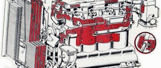
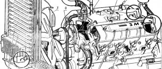
Main components of the cooling system
The engine cooling system is designed for continuous use of low-freezing liquids. The coordinated operation of the system is ensured by the main units, which include several components.
Radiator
The radiator is a tubular-ribbon element located in front of the engine. It can be three or four rows.
The radiator consists of:
- lower tank;
- cores;
- top tank.
The core consists of vertical tubes arranged in several rows. Between the tubes there are plates that give the element rigidity. In addition, the plates are able to increase the cooling surface.
The lower and upper tank are soldered to the frame. Steel plates are also attached to the tanks, forming the frame of the radiator. The inlet subpipe is soldered into the upper tank, and the outlet pipe into the lower one.
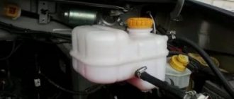
The radiator does not have a filler neck. Cooling fluid is filled through the expansion tank. You can find it on the right side of the engine.
The radiator is mounted on KAMAZ on rubber cushions at three points. It is secured on both sides with brackets, and at the bottom with a frame cross member.
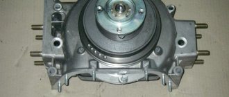
Fan
The fan is a five-blade impeller attached to a hub. The element is driven using a hydraulic coupling. The clutch automatically turns on or off depending on the engine temperature. If the clutch is turned off, the fan rotates passively from the air flow.
To enhance airflow, the fan has a casing. It is made of metal sheet. Thanks to it, the air flows exclusively to the radiator and does not disperse to the sides.
Hydraulic coupling
The fluid coupling, in contrast to the electric fan drive, operates more stably.
In the engine cooling system, it performs several functions:
- Connects and disconnects the fan from the crankshaft.
- Suppresses vibrations that occur during changes in the operation of the power plant.
Together with the regulator-switch, the fluid coupling solves a number of other important problems:
- When the engine reaches a high temperature, it automatically turns the fan impeller on and off.
- Provides optimal fan speed based on the temperature of the power plant.
The joint work of the clutch and regulator helps control the fan and the entire system as a whole.
Water pump
The water pump is an element necessary to constantly circulate coolant in the system. The pump is located at the front of the cylinder blocks. The drive is carried out through a belt, from the crankshaft pulley.
The pump consists of a housing, oil seal, bearings and impeller. Internal cavities are protected by seals. When the impeller begins to rotate, antifreeze from the lower radiator tank is directed to the pump housing and thrown towards the walls. From there the liquid enters the cooling cavity of the cylinder blocks.
Thermostat
Thermostats - have a solid filler and are designed to control the flow of antifreeze. The thermostat automatically regulates the thermal conditions of the engine and speeds up its warming up after starting.
The items are placed in a box. To monitor the behavior of the coolant, two temperature sensors on .
The first - the coolant temperature sensor KAMAZ instrument panel . The second sensor signals overheating of the liquid. If the antifreeze temperature rises to 98 °C, a warning light on the panel lights up.
Blinds
Blinds are a mechanical system consisting of metal plates attached to a frame. This element acts as a regulator of air passing through the radiator. The blinds are activated using rods and levers, directly from the cab.
An extended handle indicates that the blinds are open and vice versa. In the cold season, they help the engine warm up faster.
Removing and replacing the hydraulic coupling
- Tilt the driver's cab to the second fixed position.
- Loosen the generator mounting nut.
- Remove the fluid pump drive belt.
- Remove the engine oil sump and oil cooler.
- Unscrew the mounting bolts and remove the filter responsible for centrifugal oil purification.
- Unscrew the front bracket screws and loosen the shoe nuts.
- Raise the front of the engine and place blocks of wood under the engine.
- Unscrew the bolts and washers where the front cover is attached to the cylinder block.
- Remove the fluid coupling along with the cover and casing.
- Install the new mechanism and reassemble, performing all steps in reverse order.
Adjusting the switch (switch) of the KamAZ fluid coupling
The fluid coupling switch is the weakest point of this unit. The stability of the fan operation depends on it.
The problem is detected by the engine temperature: for example, if the temperature does not drop below 105 ° C, then most likely the switch does not operate correctly. The same reason may occur when the temperature drops below normal.
The operation of the switch is determined by the indicators of the thermal power sensor, which is in direct contact with the antifreeze, measuring the temperature and, if necessary, turns the system on/off. It is this element that is responsible for supplying oil.
Troubleshooting the switch operation involves adjusting the number of rings between the thermal power sensor and the regulator. Any experienced driver can handle such work; the fault can be easily fixed with your own hands. Most often, it is necessary to change the threshold temperature when there is insufficient cooling. In order for the fan power to increase and cooling to be intense, the number of rings must be reduced. Sometimes the problem is that the temperature has dropped too much, then rings need to be added. There are many videos in the public domain that show in detail the process of adjusting the KamAZ fluid coupling switch.
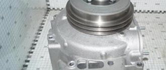
KamAZ hydraulic coupling repair
Disassembling the hydraulic fan coupling is performed in the following sequence:
- Install the hydraulic coupling on a special device. To do this, you can use a beam crane, suspension, etc.
- Unbend the locking mechanism.
- Remove the fan hub mounting.
- Press the hub off the hydraulic coupling.
- Unscrew the pulley mounting bolts and remove it.
- Remove the cuff and gasket.
- Remove the cuff bushing.
- Remove the ring from the spring mechanism.
- Remove the advance angle of the fuel injection system.
- Remove and press the driven wheel.
- Unscrew the studs from the threaded connections.
- Wash all contaminated parts with antifreeze or gasoline.