- home
- Media center
- Articles
- What is the pressure in the tractor nozzles?
Menu
- News
- Articles
- Video materials
- Photo materials
- Publication in the media
- 3D tour
28.09.2021
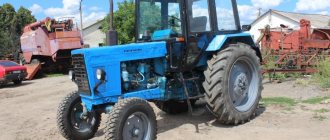
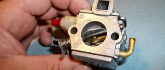
Often during maintenance and when any malfunctions occur, tractor owners think about what the pressure in the injectors should be. But here it is important to take into account both the brand of the vehicle itself and the engine. For this reason, the required pressure will have different values. Let's take a closer look at the example of the MTZ-80 tractor injectors.
Self-adjustment of injection pump MTZ. General purpose
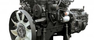
During operation of the diesel engine D-240/243 of the MTZ-80, MTZ-82 tractor, the following signs of malfunctions of the high-pressure fuel pump fuel pump may appear: the diesel engine does not start, does not develop normal power, operates unstably or operates with a smoky exhaust.
These symptoms are largely due to a fuel supply failure. The reasons for the failure of the fuel supply of diesel engines D-240/243 of the MTZ-80, MTZ-82 tractors can be: the formation of air jams in the fuel lines, the head of the fuel injection pump, filters; severe wear of the plunger pairs of the fuel pump and injector nozzles; Failure to adjust the fuel pump or incorrect installation of it on a diesel engine.
The appearance of black or gray smoke from the exhaust pipe of a diesel engine indicates incomplete combustion of the fuel, misfiring in the cylinders, or incorrect setting of the injection pump fuel supply start.
Incomplete combustion can be caused by either too much fuel entering the cylinder or too little air. It is also observed when fuel is poorly cut by injectors, the use of fuel of the wrong grade, or late fuel injection into diesel cylinders.
External signs of deteriorating injector performance include smoky exhaust, interruptions in operation and a decrease in diesel power.
To check the injectors of the D-240/243 engine of the MTZ-80, MTZ-82 tractors, set the diesel operating mode in which interruptions are most clearly audible.
Then loosen one by one the union nuts securing the fuel lines of the injectors to the fittings of the high pressure fuel pump. If the crankshaft speed does not change after loosening the nut, then the injector being tested is faulty.
If the lifting pressure of the injector needle D-240/243 of the MTZ-80, MTZ-82 tractor (injection pressure) is less than normal as a result of a change in spring stiffness or the appearance of leaks in the sleeve-plunger interface, then the duration of fuel injection will increase and the quality of atomization will decrease.
If the needle lift pressure is greater than normal or the needle is stuck in the lower position, the injection duration and the amount of fuel entering the cylinder will decrease, which also affects the starting performance of the diesel engine.
The injectors are removed from the D-240/243 diesel engine of the MTZ-80, MTZ-82 tractor and adjusted on the KI-562, KI-3333 or KI-15706 device to an injection pressure of 17.8-18.5 MPa.
The injection pressure and the tightness of the injectors can be determined without removing them from the diesel engine. To do this, use the KI-16301A device and an autostethoscope.
The device is connected to the injector under test, having previously disconnected the high pressure fuel line, and a forced fuel supply is created using the handle.
The injection pressure is set by rotating the nozzle screw D-240/243 of the MTZ-80, MTZ-82 tractor. If the pressure is not regulated, this indicates that the needle is stuck in the spray body. The quality of spraying is judged by the characteristic click heard using an autostethoscope.
The presence of such a click indicates that the needle is firmly seated in the nozzle seat at the moment the injection is completed.
The release of coolant from the radiator steam outlet pipe may indicate a violation of the tightness of the injector cup seals, breakdown and cracks in the cylinder head of the D-240/243 diesel engine of the MTZ-80, MTZ-82 tractor.
The injector glass is removed from the block head by first cutting an M24X2.0 thread on the inner surface of the glass and using a device consisting of a bracket with a power screw and a nut. The device is installed on the nozzle studs.
Difficult starting of the D-240/243 diesel engine of the MTZ-80, MTZ-82 tractor can be caused by the presence of water in the fuel, the low temperature of the mixture at the end of the compression stroke, which is insufficient to ignite the fuel.
Other reasons for difficult starting of a diesel engine may be violations of the adjustment of the advance angle of the start of fuel supply and wear of the plunger pairs of the high-pressure fuel pump.
The amount of fuel supplied to the cylinders and the smooth operation of the injectors are determined by the technical condition of the plunger pairs of the injection pump D-240/243 of the MTZ-80, MTZ-82 tractors.
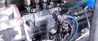
To check the technical condition of the plunger pairs, use the KI-16301A device (Fig. 1).
The device is connected to the fittings of the pump sections of the high-pressure fuel pump TNVD D-240/243 of the MTZ-80, MTZ-82 tractor, having previously disconnected the high pressure fuel lines.
If, when the diesel crankshaft is cranked by the starting device, the pressure developed is at least 30 MPa, then the plunger pair is in good condition.
During repairs, the tightness of the injection valve is checked by the time the pressure drops from 15 to 10 MPa; the fall time must be at least 10 s. If the instrument pressure gauge readings are below the given values, the high-pressure fuel pump is removed from the D-240/243 diesel engine (Fig. 2.3) and replaced.
Rice. 1. Checking the technical condition of the plunger pairs and injection valves of the injection pump D-240/243 of the MTZ-80, MTZ-82 tractors
1 — device KI-16301 A; 2 - fuel pump
Rice.
2. Removing the high pressure fuel pump D-240/243 of the MTZ-80, MTZ-82 tractor 1 - fuel pump; 2 - compressor; 3, 5 — fuel lines; 4 — pump control rod
Rice. 3. Unscrewing the bolts securing the injection pump D-240/243 of the MTZ-80, MTZ-82 tractor (front view)
1 — fuel pump drive gear cover
The appearance of gray smoke from the exhaust pipe when the diesel engine is running without load and the appearance of black smoke when the load increases indicate a late supply of fuel to the cylinders.
Hard operation of the D-240/243 diesel engine of the MTZ-80, MTZ-82 tractor, accompanied by sharp knocking sounds, and the appearance of black smoke from the exhaust pipe with increasing load indicate early fuel supply to the cylinders.
The moment at which the sections begin to supply fuel, which is used to judge the angle of the start of fuel injection into the cylinders, is one of the important parameters that affects not only the power and economic indicators, but also the starting qualities of the diesel engine.
After repair, the fuel injection pump is installed on the D-240/243 diesel engine of the MTZ-80 tractor, MTZ-82 and the angle of the start of fuel injection is adjusted. To do this, unscrew the installation bolt-stud from the threaded hole in the rear sheet of the diesel engine and insert the unthreaded part into the same hole until it stops in the flywheel.
Rotate the crankshaft by the bolt securing the fan drive pulley (Fig. 4) until the installation bolt-stud matches the hole in the flywheel; in this case, the valves of the first cylinder must be closed. This position of the crankshaft corresponds to an advance angle of the start of fuel supply equal to 26° BTDC.
A device, a momentoscope KI-4941, is installed on the fitting of the first section of the fuel injection pump D-240/243 of the MTZ-80, MTZ-82 tractor.
____________________________________________________________________________________________
During operation of the D-240 engine of the MTZ-80 tractor, the following signs of fuel equipment malfunctions may appear: the diesel engine does not start, does not develop normal power, operates unstably or operates with a smoky exhaust.
These symptoms are largely due to a fuel supply failure. The reasons for the fuel supply failure may be: the formation of air jams in the fuel lines, fuel pump head, filters; severe wear of the plunger pairs of the fuel pump and injector nozzles; violation of fuel injection pump adjustment or incorrect installation on a diesel engine.
The appearance of black or gray smoke from the exhaust pipe of a D-240 diesel engine indicates incomplete combustion of fuel, misfiring in the cylinders, or incorrect setting of the start of fuel supply by the fuel pump.
Incomplete combustion can be caused by either too much fuel entering the cylinder or too little air. It is also observed when fuel is poorly atomized by injectors, the wrong type of fuel is used, or late fuel injection into diesel cylinders occurs.
External signs of deterioration in the performance of the D-240 injectors of the MTZ-80 tractor are smoky exhaust, interruptions in operation and a decrease in diesel power.
To check the injectors, set the diesel operating mode in which interruptions are most clearly audible. Then loosen one by one the union nuts securing the fuel lines of the injectors to the fittings of the UTN-5 injection pump. If the crankshaft speed does not change after loosening the nut, then the injector being tested is faulty.
If the injector needle lift pressure (injection pressure) is less than normal as a result of a change in spring stiffness or leaks in the sleeve-plunger interface, then the duration of fuel injection will increase and the atomization quality will decrease.
If the needle lift pressure is greater than normal or the needle is stuck in the lower position, the injection duration and the amount of fuel entering the cylinder will decrease, which also affects the starting performance of the diesel engine.
The injectors are removed from the D-240 diesel engine and adjusted on the KI-562, KI-3333 or KI-15706 device to an injection pressure of 17.8-18.5 MPa.
The injection pressure and the tightness of the injectors can be determined without removing them from the diesel engine. To do this, use the KI-16301A device and an autostethoscope (Fig. 2.1.52).
Rice. 2.1.52. Determination of injection pressure and injector tightness
1 - nozzle; 2 — device KI-163101A
The device is connected to the injector under test, having previously disconnected the high pressure fuel line, and a forced fuel supply is created using the handle. The injection pressure is set by rotating the nozzle screw. If the pressure is not regulated, this indicates that the needle is stuck in the spray body.
The quality of spraying is judged by the characteristic click heard using an autostethoscope. The presence of such a click indicates that the needle is firmly seated in the nozzle seat at the moment the injection is completed.
The release of coolant from the radiator steam pipe may indicate a leak in the injector cup seals, breakdown, or cracks in the cylinder head.
The MTZ-80 injector glass is removed from the block head by first cutting an M24X2.0 thread on the inner surface of the glass and using a device consisting of a bracket with a power screw and a nut. The device is installed on the nozzle studs (Fig. 2.1.53-2.1.55).
Rice. 2.1.53. Unscrewing the nut securing the nozzle bowl
1 key; 2 — cup fastening nut; 3 - cylinder head
Rice. 2.1.54. Thread cutting in the nozzle bowl
1 — cylinder head; 2 — nozzle glass; 3 — tap M24×2.0
Rice. 2.1.55. Pressing out the injector cup from the cylinder head
1 — device for pressing out the nozzle cup; 2 — nozzle glass; 3 - cylinder head
Difficulty starting a diesel engine can be caused by the presence of water in the fuel, or the low temperature of the mixture at the end of the compression stroke, which is insufficient to ignite the fuel.
Other reasons for difficult starting of the D-240 engine of the MTZ-80 tractor may be violations of the adjustment of the advance angle of the start of fuel supply and wear of the plunger pairs of the high-pressure fuel pump (TNVD UTN-5).
The amount of fuel supplied to the cylinders and the smooth operation of the injectors are determined by the technical condition of the plunger pairs of the fuel pump. To check the technical condition of the plunger pairs, use the KI-16301A device (Fig. 2.1.56).
The device is connected to the fittings of the pump sections of the high-pressure fuel pump, having previously disconnected the high-pressure fuel lines. If, when the diesel crankshaft is cranked by the starting device, the pressure developed is at least 30 MPa, then the plunger pair is in good condition.
The tightness of the discharge valve is checked by the time the pressure drops from 15 to 10 MPa; the fall time must be at least 10 s. If the instrument pressure gauge readings are below the given values, the injection pump is removed from the diesel engine (Fig. 2.1.57, 2.1.58) and replaced.
Rice. 2.1.56. Checking the technical condition of plunger pairs and injection valves of the MTZ-80 injection pump
1 — device KI-16301 A; 2 - fuel pump
Rice. 2.1.57. Removing the high pressure fuel pump
1 - fuel pump; 2 - compressor; 3, 5 — fuel lines; 4 — pump control rod
Rice. 2.1.58. Unscrewing the fuel pump mounting bolts (front view)
1 — cover of the fuel pump drive gear D-240
The appearance of gray smoke from the exhaust pipe when the diesel engine is running without load and the appearance of black smoke when the load increases indicate a late supply of fuel to the cylinders.
Hard operation of the diesel engine, accompanied by sharp knocks, and the appearance of black smoke from the exhaust pipe with increasing load indicate early fuel supply to the cylinders.
The moment at which the sections begin to supply fuel, which is used to judge the angle of the start of fuel injection into the cylinders, is one of the important parameters that affects not only the power and economic indicators, but also the starting qualities of the diesel engine.
After installing a new or repaired MTZ-80 fuel injection pump on a D-240 diesel engine, the angle at which the fuel injection begins is adjusted. To do this, unscrew the installation bolt-stud from the threaded hole in the rear sheet of the diesel engine and insert the unthreaded part into the same hole until it stops in the flywheel.
Rotate the crankshaft by the bolt securing the fan drive pulley (Fig. 2.1.60) until the installation bolt-stud matches the hole in the flywheel; in this case, the valves of the first cylinder must be closed. This position of the crankshaft corresponds to an advance angle of the start of fuel supply equal to 26° BTDC.
A device, a momentoscope KI-4941, is installed on the fitting of the first section of the UTN-5 fuel pump (Fig. 2.1.61). Open the cover of the injection pump drive gear, bend the locking plate antennae and unscrew the bolts securing the pump camshaft drive flange to the gear (Fig. 2.1.62).
Pump the power system with a hand pump until fuel comes out of the filter drain tube without air bubbles. Set the fuel supply lever to the full supply position and rotate the fuel pump shaft clockwise several times until the momentoscope tube is filled with fuel (Fig. 2.1.63).
Rice. 2.1.60. Cranking a diesel engine
1 — diesel rear sheet; 2 - bolt-stud
Rice. 2.1.62. Unscrewing the pump camshaft drive flange bolts
1 - splined flange; 2 - locking plate
Rice. 2.1.64. Adjusting the axial clearance of the injection pump drive gear
1 - adjusting bolt; 2 - lock nut
Lightly shake the tube to remove some of the fuel from it and carefully rotate the pump shaft clockwise until the fuel level (meniscus) in the glass tube of the momentoscope begins to rise.
Holding the pump shaft bolt from spontaneous rotation with a wrench, find holes on the splined flange that coincide with the gear holes, screw in the fastening bolts and secure them with a locking plate.
After installing the pump drive gear cover, adjust the axial clearance of the fuel pump drive gear using bolt 1 (Fig. 2.1.64). Having released the lock nut, screw in the adjusting bolt until it stops, then unscrew it half a turn and end with the nut.
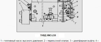
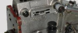
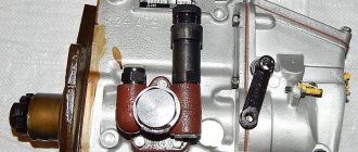
The high pressure fuel pump (HPFP) is mounted in one unit with the regulator and booster pump, made of durable aluminum alloy and installed on the left side of the engine, bolted to a cast iron cover. Driven by the crankshaft. It is available in two versions to choose the method of mounting the flange on which the regulator is installed. There is a partition inside that divides the pump into two sections.
The lower section contains the cam shaft with the drive, and the upper section contains the individual pump sections. Their task is to supply fuel under high pressure at a given time and in a certain dose. In this case, the portion of fuel is measured accurately. The injection pump is connected to the engine using a cast iron plate, which is installed in the front part of the heat pump; in the rear part there is a flange for attaching the regulator.
Related Posts
Why is something leaking through the manifold and muffler connection on the MTZ 82 D243 engine? It starts well, pulls well - no smoke.
Hello, can you tell me if anyone has encountered such a problem as whether or not it flows like oil through the manifold and muffler connection on the MTZ 82 D243 engine. It starts well, it also produces no smoke, what could be the reason? - Alexander
Why does my MTZ-82 engine D 243 throw oil into the exhaust pipe? The caps were replaced.. The piston was changed.
Guys, tell me, my MTZ-82 engine D 243 throws oil into the exhaust pipe. I replaced the caps and the same thing happened. The piston was changed two years ago. The tractor was taken away by another tractor driver for 5 days and this started, but before that everything was fine. Help me please .
What pressure should be in the wheels of an MTZ 82 with a beam axle under 1.2 tons?
Hello everyone, what should be the pressure in the wheels of an MTZ 82 with a beam axle under 1.2 tons, thanks in advance!
Why, after replacing the injection pump, did the engine on the MTZ 82 begin to overheat? The gasket was broken - they replaced it, reset the ignition, adjusted the valves. The problem remained.
Good afternoon ! After replacing the injection pump, the engine on the MTZ 82 began to overheat, such problems had not been observed before, has anyone encountered this? After two months of operation, at temperatures closer to 100 degrees, the cylinder head gasket blew, we replaced it, changed the ignition, adjusted the valves, but the problem still remained! The radiator itself is clean, but aluminum, there seems to be circulation! They advise installing a fan with 6 blades instead of 4, and installing a diffuser, but I think this will not solve the problem, it heats up even without much load in about 30 minutes of operation! Thanks in advance for the answers.
Why does the MTZ engine D240 have 3.5 pressure when cold, but when it warms up it disappears?
Good afternoon, friends, please tell me the Mtz engine D240 on cold pressure 3.5 and when it warms up it disappears, in general there is no reason. Thanks in advance.
Why, when you lift the kun, does it rise slowly? Is it the distributor or the pump that is causing the pressure at the distributor?
Salamaleikum to everyone! the problem is when you lift the kun it lifts slowly I don’t know what the reason is in the distributor or in the pump the pressure on the distributor was still pulling and when I put the forks the cylinder on the forks does not press the air, it expelled the air anyway, please tell me what the reason is, thanks in advance
Tractor MTZ 82, engine 243, head from 240. Why doesn’t the rocker arms lubricate after repair?
Hello guys, this is a problem. Tractor MTZ 82, engine 243, head from 240. Does not lubricate the gears after repair. Everything was assembled perfectly, all channels were blown out, the pressure was 2. But the caramysl doesn’t lubricate, what could be the problem? Good luck to the admin
Hydraulics MTZ82, cylinder on peak (Lex). Why are the cuffs tearing, there are no scuffs? Maybe something to do with the pressure?
Hi all! Tell me, the MTZ82 hydraulics, the cylinder is on the peak (Lex), tears the cuffs, scuffs, etc., everything is fine, maybe something with the pressure? What to do? Where to look for the reason? Thanks in advance.
Why does the MTZ-82 throw the filler cap, where we fill the oil, onto the engine? The breather is clean.
Hello guys! This is the problem on the MTZ-82, it throws out the cap from the neck where we pour oil onto the engine. Some people say the breather is clogged, But the breather is not clogged, but the breather is not clogged. What is the problem? Has anyone encountered this? Thanks for the answers.
Why does the new generation MTZ 82.1 transfer oil from the hydraulic tank to the engine? We replaced the nsh-10 pump.
Colleagues, please tell me the oil on the new generation MTZ 82.1 distills from the hydraulic tank to the engine, we changed the nsh-10 pump, everything is fine for a week and then it starts distilling again in a new way.
Source
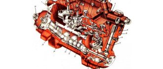
Main parts of fuel injection pump and their design
The cam shaft is made with cams symmetrically located to each other. Between the second and third cams there is an eccentric that drives the fuel lift pump. The MTZ injection pump plunger pair consists of a plunger and a bushing, which perform the main work in the fuel pump. Thanks to them, high pressure is created when fuel is supplied to the engine and the required portion of fuel is supplied. The plunger and bushing are made of high-quality metal (steel) and are subsequently subjected to heat treatment. This technology allows you to create the necessary parameters of parts and their compatibility to prevent fuel leakage. Therefore, if one of the elements wears out, the entire paired part must be replaced, and not just one of the elements.
The upper part of the plunger pair bushing has a significant thickening. It is this part that is subject to the greatest pressure. In the same place on the bushing there are two holes: suction and bypass. Through the suction hole, fuel enters the volume free from the plunger, and through the bypass, the flow of fuel stops. The MTZ injection pump plunger is a cylindrical rod, along the surface of which there are two symmetrically located spiral recesses. One of them serves to change the supply of fuel injected into the engine. When the edges of the bypass hole of the bushing and the recess of the rod coincide, the pressure in the space free from the plunger decreases sharply and fuel does not flow into the nozzle. The other hole regulates the fuel pressure. At the bottom of the plunger there are two protrusions for controlling rotation and a head on which the spring plate rests.
The injection valve of the MTZ injection pump isolates the free space from the flow of fuel. When the fuel supply stops, the pressure drops sharply. The valve seat is carefully selected to ensure a tight fit. They are carefully processed and adjusted to each other, so it is not allowed to disturb the completeness of the part.
The movement of the valve in the seat is carried out by a cross-shaped shank, between the supporting belts of which fuel is passed. When the fuel supply stops, the spring located above the valve presses on it, trying to press it to the seat. At the same time, the unloading belt first isolates the fuel line from the overplunger tank, and then pumps out part of the fuel, thereby reducing the high pressure. This action helps to abruptly stop the fuel supply.
Operating principle of fuel injection pump MTZ
The principle of operation of the fuel pump is simple: when the cam shaft rotates, its protrusion encounters the roller and the pusher rises, then the spring lowers it. This action occurs simultaneously with the movement of the plunger inside the sleeve. When the plunger moves down, the fuel fills the space vacated by it. When the movement occurs upward, the plunger compresses the fuel. The created pressure causes the injection valve to open, releasing fuel into the injector. At this moment, the fuel supply stops. The amount of fuel supplied depends on the distance that the plunger will travel from the moment the inlet port is closed until the bypass hole opens. This distance can be changed. The plunger rotation mechanism serves this purpose. It consists of a rack with a toothed rim, connected by means of a rod to the pedal and lever of the driver's cabin. Under the influence of traction, the rack begins to move, turning the gear rims at the same time as the plunger sleeve, and the fuel supply changes.
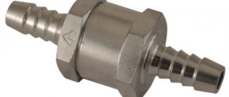
Due to the high pressure during fuel supply, timely and precise injection of fuel occurs during subsequent supply. If the pressure in the fuel line decreases slightly, the injector will not be able to inject accurately. To maintain the required pressure, a bypass valve located in the upper rear part of the fuel pump housing is connected. Through it, excess fuel is returned to the suction cavity. In this way, the pressure is maintained in the range from 0.007 to 0.12 MPa.
Maintenance and adjustment of fuel injection pump MTZ
When servicing the fuel pump, it is necessary to periodically check the oil level (after 120 hours of operation) and replace it (after 480 hours). Every 1000 hours of operation, it is recommended to check that the fuel pump meets the technical parameters. If necessary, adjust it. It is necessary to adjust the pump parameters on a special stand, equipped with instruments for carrying out measurements and other tests. You will also need a measuring container to calculate the volume of fuel supplied, as well as a drive with a variator. Before removing the pump from the diesel engine, it is necessary to prepare caps and plugs to cover the holes in the fuel lines, clean the pump of contaminants, disconnect the control rod, tubes and close them with plugs. Unscrew the bolts securing the timing gear shield and remove the pump from the engine. Close the holes in the shield with a lid. When removing the pump, you should not disconnect the splined flange from the gear so as not to change their location, which determines the state of the setting angle of advance of the fuel supply to the engine. Assembling the pump proceeds in reverse order.
The speed mode is adjusted using a special screw screwed into the regulator body and limiting the voltage of the regulator. Unscrewing the screw increases the frequency of the regulator, and tightening it correspondingly decreases it. The minimum permissible number of rotations when idling is adjusted automatically when the control lever is moved to the appropriate position.
The volume of incoming fuel can be adjusted by rotating the eccentric pin. Turning it down increases the feed, turning it up decreases it.
Checking the initial phase of fuel supply is carried out as follows:
— use the lever to set the maximum fuel supply mode;
— disconnect the high-pressure tube from the fitting of the first section, and put a substitute (momentoscope) in place of the removed tube;
— turn the engine crankshaft with a key until a stream of fuel without air bubbles appears from the glass tube of the momentoscope; — having removed some of the fuel from the tube, slowly rotate the crankshaft until the fuel begins to rise in the momentoscope tube; at the same time, monitor the fuel level in the tube; — having unscrewed the bolt, insert its opposite end into the same hole until it rests against the flywheel; in this case, you need to check that the bolt coincides with the hole in the flywheel; — insert the high-pressure pipe and screw the installation bolt into the hole in the rear sheet; — fasten the mounting bolts of the front flange, replace the manhole cover and adjust the axial clearance of the MTZ fuel injection pump drive gear. The service life of the fuel injection pump of the MTZ tractor is quite reliable and long, but it is necessary to carry out timely maintenance and adjustment. This will extend the service life and save the driver from problems while driving.
Engine injector pressure d 240
Injector maintenance involves periodically checking the quality of fuel atomization and injection start pressure.
After every 960 hours of operation (at maintenance No. 3), remove the injectors from the engine and check them on a bench. An injector is considered to be in working order if it sprays fuel in the form of a mist from all four nozzle holes, without separately flying drops, continuous streams or thickenings. The beginning and end of the injection must be clear; the appearance of drops on the toe of the nozzle is not allowed. The injection start pressure is 165-180 kgf/cm2. Check the spray quality at a frequency of 60-80 injections per minute.
If fuel atomization is poor, disassemble the injector, clean the parts from carbon deposits and rinse. Clean the nozzle holes with a special needle (a string with a diameter of up to 0.28 mm).
Promotional offers based on your interests:
When disassembling the nozzle, first unscrew the cap, loosen the nut, unscrew the adjusting screw (thus loosening the spring), then unscrew the nozzle nut and remove the nozzle.
To do this, unscrew the nozzle cap, loosen the nut and use the adjusting screw to change the spring tension until the injection start pressure is 175 kgf/cm2.
If the work performed does not improve the quality of fuel atomization, replace the nozzle.
Tighten the injector mounting bolts evenly to a torque of 2.0-2.5 kgf-m.
Everything about the MTZ-82 tractor: design, operation, repair, technical characteristics and repair. Engine D-240: MTZ engine repair.
Watch video - Principle and design of injection pump
The main components and parts of the injection pump (high pressure fuel pump) MTZ are the pump body, plunger pairs, cam shaft, valves, regulator. Failure or incorrect operation of these components leads to unstable operation of the engine, the engine troits (not all cylinders work), the engine stalls, picks up speed poorly or does not pick up at all.
All these points need to be eliminated because... this can lead to breakdown of the engine itself, and this is an expensive repair. Therefore, timely maintenance and adjustment must be carried out within the time limits specified in the operating manual.
Before starting the adjustment.
The first thing we need to make sure is that the cause of the above faults is indeed due to the pump. Because if you adjust the pump and do not get the desired result, you will be disappointed, and perhaps confused, what to do next. Make sure the fuel priming pump is working properly, the injectors are working properly, the fuel filter should be clean, and there should be no fuel leaks.
Having made sure that all the components specified in the paragraph are in working order, we proceed to adjusting the pump itself. Since our article is called “self-adjustment,” we will adjust the pump without removing it from the engine.
The peculiarity of adjusting such a pump is that the adjusting bolts are located on the regulator body and inside the pump itself. Bolt-23 (Fig. 1) regulates the maximum engine speed. By twisting and unscrewing it, you increase or decrease them accordingly.
Engine idle speed is adjusted by increasing or decreasing the fuel supply to the injectors per stroke of the plunger. The adjustment is carried out using a bolt of nominal value 17 (Fig. 1). When the bolt is tightened, the amount of fuel increases, and when unscrewed, it decreases; accordingly, the engine speed increases or decreases. Engine idle speed should be minimal but stable. The uniformity of fuel supply to each section is also regulated.
The uniformity of the feed is regulated by turning the sleeve of the plunger pair-11 (Fig. 2). This adjustment is carried out on special stands. This is one of the main characteristics of the pump. The uniformity of feeding can be adjusted independently. To do this, you need a measuring container with the lowest possible division value (for more accurate data), a well-charged battery, and an assistant.
We unscrew all the injectors so that the engine starts (and it will be easier for the battery). We connect the nozzle to the first section of the pump. We insert it into the measuring container so that as little fuel as possible goes beyond its limits (it’s better that it doesn’t go at all). We crank the engine with the battery and count the number of injections that the injector made (the more, the better the difference will be visible). We perform this operation with each section. The difference between sections should not exceed 6%. If, according to the measurements, the difference is greater, then we adjust the corresponding section.
Remove the side cover of the pump. We release the coupling screw-15 (Fig. 2) and very carefully turn the rotary sleeve by pointing a screwdriver at it and slowly tapping it. Depending on the fact that we need to increase or decrease the amount of fuel, then by turning the sleeve to the left we increase the amount, and by turning it to the right we decrease it. Tighten the coupling screw-15 (Fig. 2).
After this, we check again using a measuring container. We adjust until we achieve the desired indicator.
We just replaced the stand with our engine, since it imitates an engine, it just has more instruments. But if there is no access to such a stand, then this method will effectively replace it.
It is also necessary to check the fuel injection start angle using a torque scope. Don't be intimidated; it's easy to do it yourself. Take a piece of fuel pipe with a nut at one end (to screw it to the pump section), put a piece of transparent hose on it - the momentoscope is ready.
We connect it to the first section of the pump. We turn the engine as it rotates until fuel appears in the hose. We turn it further until the fuel stops rising. There is an installation bolt on the flywheel housing, and a hole (mark) on the flywheel itself. We unscrew the bolt and make sure that the hole from the bolt coincides with the hole in the flywheel. This parameter can be adjusted using the pusher bolt-5 (Fig. 1). To decrease the angle, unscrew the bolt, to increase it, tighten it. Don't forget to secure it with a locknut.
Fuel injection pump malfunctions at MTZ and their causes.
One of the main malfunctions of the MTZ injection pump is wear of the plunger pair. Due to friction, the working surfaces of the plunger and sleeve are actuated. This wear occurs due to small solid particles that are found in the fuel. The presence of a large amount of sulfur in the fuel also leads to increased wear. Worn plunger pairs are replaced with new ones or restored. Change filters in a timely manner. The entire fuel system, especially the injection pump, is very afraid of the presence of water in the fuel. Because of this, water hammer occurs in the plunger pairs, which leads to the destruction of pump parts. These are the main malfunctions and their causes.
Maintenance of fuel injection pump MTZ.
All maintenance comes down to timely replacement or adding oil to the pump. On newer versions, pump lubrication is centralized. Here you need to monitor the oil in the engine.
I hope, dear readers, this article has helped you understand the technical issues that interest you regarding the repair and adjustment of injection pumps installed at MTZ. Thank you all for your attention!
The high pressure fuel pump (HFP) is one of the most complex mechanisms in the vehicle fuel system. It carries out the process of supplying fuel to the engine. The high pressure fuel pump is used in trucks, cars and special equipment. The distribution type injection pump contains a high pressure injection element. The fuel pumps are equipped with an individual injection system for each cylinder, and short high-pressure lines provide maximum injection pressure. An electronic high-pressure fuel pump ensures economical operation of the diesel engine. Fuel is supplied to each cylinder through an electronic control system.
Competent repairs of MTZ fuel injection pumps will only be done at a service center. The process of repairing a high-pressure fuel pump is quite complex and time-consuming. It includes diagnostics on specialized stands equipped with software, repair of pump components, testing and adjustment. Repair of MTZ fuel injection pumps in special service centers will be carried out by experienced craftsmen. This will eliminate low-quality quick repairs that could be done in some dubious place.
Adjustment or repair of the injection pump should be done in the following cases:
- increasing vehicle fuel consumption;
- no fuel supply from the pump to the injector;
- jamming of the plunger pair in the pump;
- difficulty starting the engine;
- reducing diesel power;
- the appearance of smoke and extraneous noise.