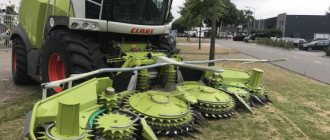
How to avoid broken grain
The threshing drums force the grain to move faster through the threshing machine. If the grains that have picked up speed unsuccessfully hit the concave, they break. The process of grain crushing is enhanced if there is no protective layer of straw in the thresher, that is, when the thresher is not fully loaded.
The problem of grain crushing during threshing began to receive attention only a few years ago. A fact that few people know is that the economic losses associated with broken grain can easily exceed the losses in the key or rotary mechanism, or cleaning. Anything that doesn't leave the combine with straw ends up in the grain bin. This can have a pretty significant impact on the selling price. Around 2011, designers and engineers joined the discussion. The fact is that around the same time the share of axial combines on the market increased. In terms of grain crushing, rotary combines often perform better than classic tangential threshers.
Does the rotor really rejuvenate more gently?
The processes associated with threshing are, in principle, the same for all designs - impact, friction and centrifugation. But depending on the units used for threshing and separation, there may be significant differences.
- Harvesters with a tangential thresher produce more impact threshing. It does not matter whether these combines have additional separating rotors for separation in the form of accelerators (Claas, Sampo) or centrifugal separators (Deutz-Fahr, Fendt, John Deere, Massey Ferguson, New Holland). All combines have a limited threshing path between the threshing drum and the concave. In this area, intensive threshing and separation occurs.
- Hybrid combines have axial rotors installed behind the tangential thresher (Claas Lexion Rotor, John Deere C series). The efficiency of residual grain separation using rotors is many times higher than that of straw walkers. Therefore, even with structurally identical threshers, there will always be much more straw in the space between the deck and the drum, which reduces the intensity of grain crushing.
And if the thresher is set to a too gentle mode, then the rotors thresh the remaining grains - this is a big advantage of this design compared to straw walkers.
- Axial combines can have one rotor, such as those from Case, Fendt, John Deere or Massey Ferguson, or two rotors - New Holland.
The rotors receive the mass and carefully move it in a spiral. In this regard, the threshing process occurs to a greater extent due to friction rather than due to impact. Due to this, the grain itself is processed in a gentle manner, but the straw is greatly abraded.
In the same way as with tangential threshing devices, the combine operator here can change the rotor speed and the size of the concave clearance without leaving the cab.
Already during tests carried out in the 70s, it was found that axial-rotor combines crush grain less than combines with tangential threshing. The proportion of broken grain in them rarely exceeds 1%, even if combining is carried out in a hard mode, that is, with a high rotor speed and a small threshing gap.
Combine harvesters with a tangential threshing system and a straw walker behave differently. If high throughput is needed, then threshing is carried out in a hard mode. that is, with a small threshing gap and a high drum speed. Then, with a peripheral speed of the drum of 33 m/sec, the number of impact points (the frequency of impacts of the whips multiplied by the number of concave slats) will be 135 thousand. The risk of grain damage increases accordingly. This does not happen with axial type combines, since the grain does not hit the concave slats in a straight line.
With proper settings - no more than 1% broken grain
At the DLG test center, during numerous combine inspections carried out since the early 1980s, the proportion of broken grain in straw walker combines exceeded 11%. This, in principle, is quite realistic if, at low grain humidity, the combine is configured exclusively for maximum throughput. From an economic point of view, such a percentage of broken grain is not economically profitable.
The fact that, with appropriate settings, a keyboard straw walker will also show good results is confirmed by the institute’s own results. Sometimes the proportion of broken grain was less than 1%.
Farmers and agricultural contractors who switched from straw walker combines to hybrid ones were generally pleasantly surprised by the lower percentage of broken grain. Even with a similar threshing setup, the same as that of combines with a straw walker, the percentage of broken grain in these combines, all other things being equal, is lower. This can only be due to a thicker layer of material in the threshing gap - straw softens.
And if you thresh in an even softer mode with a threshing gap increased by 2-3 mm and the peripheral speed of the drum reduced by 3-5 m/sec, then the quality of work will be almost the same as that of axial combines. Even with grain moisture content of about 12%, the share of crushed grain in this case will still be less than 1%.
Discussions that axial combines have, in principle, a lower percentage of crushed grain than keyboard or hybrid ones are not always acceptable. Although the danger of very hard threshing is higher with a tangential thresher, professional combine operators have proven time and time again that high quality grain can be obtained with both tangential and hybrid combines. Before setting up the combine, the harvester must evaluate the harvesting conditions. The well-known technique of rubbing the ear can help him with this. An experienced combine operator will immediately see in what mode the grain needs to be harvested - soft or hard. Difficulties arise with large grains that are easily separated in the middle of the ear and grains that are firmly seated at the base and (or) tip of the ear. Then the adjustment becomes a balancing act between grain crushing and threshing losses, as well as unseparated chaff.
The influence of grain moisture is often not taken into account. But the lower its humidity, the harder and more fragile the grain becomes, and the greater the likelihood of its crushing! For most cereals, the percentage of broken grain increases, all other things being equal, when the grain moisture content is below 13-14%. However, the tendency of grain to crush may also depend on the variety.
Often the combine operator sets the thresher to too hard a mode
Many combine harvesters have their threshing machine set to too hard a setting. As a rule, it is the inexperienced combine operator who acts on the principle “you can’t spoil the porridge with oil” and sets the drum rotation speed higher and the threshing gap smaller, believing that in this case the grain will be threshed completely, and everything will be fine with productivity. Of course, the separation of grain in the concave improves with increasing speed of the threshing drum. With ripe bread and low grain moisture, the gap of the threshing drum should be increased to avoid grain crushing.
Depending on the system, the basic settings of combines can vary greatly. In this case, combines with a key straw walker and standard threshing machines or threshing machines with a centrifugal separator are called for wheat; as a rule, the peripheral speed of the threshing drum is from 23 to 35 m/sec. This corresponds (depending on the diameter of the threshing drum from 45 to 75 cm) to a rotation speed of 1000-600 rpm to 1500-900 rpm. In powerful combines, it is best to use the basic settings already saved in the computer memory, because Reprogramming using the instruction manual may result in errors.
Threshers with an accelerator are set to lower peripheral speeds - from 23 to 25 m/sec, which, depending on the drum diameter from 45 to 60 cm, corresponds to a rotation speed from 980-730 rpm to 1060-800 rpm. Based on the settings of a standard thresher, it is often set to a too harsh mode.
For axial type threshers, manufacturers recommend basic settings from 30 to 37 m/sec. With a rotor diameter of 43 to 80 cm, this corresponds to a rotation speed from 1300 - 750 rpm to 1650-900 rpm. The rotors develop maximum peripheral speeds of up to 44 m/sec, at which grain in conventional combines would have been crushed long ago.
How can you prevent grain crushing?
Good combine operators control the threshing result. Unfortunately, this is not always easy to do when chopping straw. But even in this case, you can make a short stop, turn off the combine, and take a straw sample through the hatch leading to the keys. Or the straw is placed in a windrow over a short section, and after control and adjustment of the combine, it is picked up and chopped again. The time and effort spent on this are, as a rule, completely worth it. There is another sign indicating the presence of a large amount of broken grain - damaged mealy bodies give the threshed mass in the bunker a whitish tint.
The combine operator has a certain set of possible actions at his disposal. Guided by his instinct, he must find the optimal value. Whatever action he performs, you need to remember that sensors will not help here.
- Increase the speed of movement, provided that the combine operates without losses. At first glance this may seem unusual. But with increased throughput, there will be more straw in the threshing gap, and the intensity of grain crushing will decrease.
Typically, productivity and quality can only be improved to a certain extent at the same time. Basically, depending on the harvesting conditions, only more
soft threshing - reducing the drum speed and increasing the concave clearance.
- Reduce the drum rotation speed if the grain-to-ear bonding forces are still high. To avoid losses during threshing, it is necessary to keep the threshing gap small.
- Increase the threshing gap if the grain is better ripened.
- If possible, turn off the chatter. After harvesting winter barley, combine operators often forget to turn off the shastalka. It reduces the concave area and thus the grain separation. And, due to high friction, the proportion of broken grain increases.
But there is no need to rush into this. It is quite possible that it would be wiser to use Shastalka on wheat and triticale. If firmly seated wheat grains are threshed with difficulty and only with unseparated chaff, or the proportion of pieces of broken triticale ears in the harvest is too large, then by connecting a shastalka the quality of work can be improved (at least the proportion of broken grain will remain the same). To do this, the combine operator must generally increase the threshing gap.
- Remove the bars: Many combine harvesters are equipped as standard with additional cross bars in case of extreme harvesting conditions. For normal conditions of harvesting grains and rapeseed they are not needed, so these slats must be dismantled. Any combine operator should remember these basic rules before going into the field for the first time.
- Minimize misalignment by selecting the appropriate size of the openings of the upper and lower sieve, because Crushing of grain occurs not only in the thresher. Often the reason for crushing is the presence of too large a share of pure grain in the collection. The fact is that these grains can again be subject to damage. In final threshing devices, combine operators often forget to replace elements for difficult-to-thresh crops with simple metal guides, which again can enhance the grain crushing process.
Grain crushing: correct assessment of losses
What is the actual proportion of broken grain? To determine this value, you need to take a sample from the bin - weigh 100 g of grain and manually select damaged grains. Then it is necessary to determine their percentage in a given sample. This method has received general acceptance and widespread use.
And yet, how much broken grain remains on the field after the harvester passes. In the literature, there is often an opinion that only 50% of broken grain is in the bunker, while the ratio of the share of broken grain in the bunker to losses is 1:1.
If, in accordance with this method, we double the maximum 11% given by the DLG center, it turns out that the tested combine actually produces 22% broken grain. How much broken grain will remain on the field cannot be determined on the basis of any theoretical reasoning.
It is best for the average practitioner to take measurements using some kind of measuring cup.
In experiments with a combine harvester with a key straw walker and a high proportion of broken grain, due to the conscious use of a strict threshing regime, the ratio of the proportion of broken grain in the bunker to losses on the field ranged from 11:1 to 1.4:1. And the higher the total proportion of broken grain, the greater the amount of it was in the grain bin of the combine.
Depending on the design and settings of the combine, these ratios may vary. Even with seemingly clean work, the value of grain losses can be quite high due to the presence of a high proportion of broken grain and flour in the total mass. Therefore, an approximate calculation of the overall result under other harvesting conditions and other combines is not always acceptable.
Let's sum it up
The quality of grain is determined to a greater extent by the settings of the combine than by the threshing system.
With the help of axial combines, it is indeed possible to obtain a small proportion of broken grain - less than 1%. This, however, is also possible with optimal settings for both tangential and, above all, hybrid combines. Because tangential combines are designed to withstand both extremely heavy and wet harvesting conditions, the combiner may make more mistakes when setting them up for dry conditions, leading to more broken grain.
To assess combine losses, it is important to take into account both the proportion of broken grain in the bunker and the grain losses behind the combine. The experimental results show that one cannot rely on any simple rules. In addition to the cleaning design and harvesting conditions, the setting of the combine is decisive - the largest proportion of broken grain, as a rule, ends up in the bunker.
To avoid a high percentage of broken grain, the combine operator can use various settings. But in order to optimize it, he must know well the result of applying all options. Due to the fact that a beginner himself often cannot correctly assess the settings, tangential threshers in combines usually operate in a very harsh mode. Here, advice from an experienced combine operator received over the phone or the use of setting up modern information systems for optimization can help.
Electrical diagram of VAZ-2121
1 – side direction indicators; 2 – front lights; 3 – VAZ-2121 headlights; 4 – electric motors for headlight cleaners; 5 – sound signals; 6 – relay for turning on the headlight cleaners and washer; 7 – relay for turning on low beam headlights; 8 – relay for turning on the high beam headlights; 9 – windshield washer electric motor; 10 – sensor of insufficient brake fluid level; 11 – plug socket of a portable lamp; 12 – oil pressure warning lamp sensor; 13 – oil pressure indicator sensor; 14 – coolant temperature indicator sensor; 15 – ignition distributor; 16 – spark plugs; 17 – windshield wiper motor; 18 – ignition coil; 19 – generator; 20 – carburetor shut-off valve; 21 – VAZ-2121 starter; 22 – headlight washer motor; 23 – voltage regulator; 24 – battery charge warning lamp relay; 25 – battery; 26 – windshield wiper relay; 27 – additional fuse block; 28 – main fuse block; 29 – parking brake warning lamp switch; 30 – switch for differential lock warning lamp; 31 – reverse light switch; 32 – switch for the carburetor air damper warning lamp; 33 – brake light switch; 34 – heater electric motor; 35 – relay-interrupter for direction indicators and hazard warning lights; 36 – additional resistor of the heater electric motor; 37 – instrument lighting switch; 38 – headlight switch; 39 – direction indicator switch; 40 – sound signal switch; 41 – wiper switch; 42 – windshield washer switch; 43 – ignition switch; 44 – external lighting switch; 45 – heater switch; 46 – switch for headlight cleaners and washer; 47 – cigarette lighter; 41 – alarm switch; 49 – lamp switches located in the door pillars; 50 – oil pressure gauge with insufficient pressure warning lamp; 51 – fuel level indicator with fuel reserve warning lamp; 52 – tachometer; 53 – parking brake warning lamp; 54 – battery charge indicator lamp; 55 – control lamp for the carburetor air damper; 56 – speedometer; 57 – indicator lamp for external lighting; 58 – turn signal indicator lamp; 59 – control lamp for high beam headlights; 60 – relay-interrupter for the parking brake warning lamp; 61 – brake fluid level warning lamp; 62 – differential lock warning lamp; 63 – coolant temperature indicator; 64 – lampshades; 65 – sensor for level indicator and fuel reserve; 66 – rear lights; 67 – license plate lights.
Motor control circuit
Connection diagram of the VAZ-21214 engine management system with central fuel injection under US-83 toxicity standards with controller 21214-1411010 (EFI-4 type) on VAZ-21214 vehicles:
1 - control lamp “CHECK ENGINE”; 2 – instrument cluster (fragments); 3 – electric fans of the engine cooling system*; 4 – electric heater of the intake pipe; 5 – air temperature sensor; 6 – absolute pressure sensor; 7 – coolant temperature sensor; 8 – block connected to the throttle position sensor; 9 – central fuel injection unit; 10 – block connected to the idle speed regulator; 11 – block connected to the nozzle; 12 – diagnostic block; 13 – controller; 14 – knock sensor; 15 – speed sensor; 16 – oxygen concentration sensor; 17 – adsorber; 18 – battery; 19 – main relay; 20 – fuse block for the engine control system; 21 – relay for turning on the electric fuel pump; 22 – relay for turning on the electric fan*; 23 – relay for turning on the electric heater of the inlet pipe; 24 – electric heater protection fuse; 25 – starter activation relay; 26 – ignition relay; 27 – main car fuse box (fragment); 28 – spark plugs VAZ-21214; 29 – tachometer; 30 – electric fuel pump with fuel level sensor; 31 – ignition module; 32 – crankshaft position sensor; 33 – courtesy light switch, located on the driver’s door pillar; 34 – control unit of the automobile anti-theft system**; 35 – status indicator of the car anti-theft system**; A – wire going to plug “50” of the ignition switch; B – wire going to plug “15” of the ignition switch; B – wire going to terminal “30” of the generator; G – rear wiring harness wires connected to the fuel level indicator; D – rear wiring harness wire connected to switch 33.
Useful: Sensor with car washer fluid level indicator
Connection diagram of the VAZ-21214 engine management system with distributed fuel injection under Euro-2 emission standards with controller 2123-1411020-10 (MP 7.0 type) on VAZ-21214 vehicles:
1 – warning lamp of the engine management system; 2 – instrument cluster (fragments); 3 – electric fans of the engine cooling system; 4 – courtesy light switch, located on the driver’s door pillar; 5 – status indicator of the car anti-theft system; 6 – control unit of the automobile anti-theft system; 7-coolant temperature sensor; 8 – air flow sensor; 9 – throttle unit; 10 – block connected to the throttle position sensor; 11 – block connected to the idle speed regulator; 12 – controller; 13 – oxygen concentration sensor; 14 – knock sensor; 15 – crankshaft position sensor; 16 – speed sensor; 17 – adsorber; 18 – battery; 19 – main relay; 20 – diagnostic block; 21 – fuse block for the engine control system; 22 – relay for turning on the electric fuel pump; 23 – relay for turning on electric fans; 24 – main car fuse box (fragment); 25 – block connected to the additional wiring harness*; 26 – ignition module; 27 - tachometer VAZ-21214; 28 – electric fuel pump with fuel level sensor; 29 – nozzles; 30 – spark plugs; A – rear wiring harness wire connected to switch 4; B – wires connected to plug “1” of fuse block 24 (one wire goes to plug “15” of the ignition switch, and the other to plug “85” of the ignition relay); B – rear wiring harness wires connected to the fuel level indicator.
The order of conditional numbering of plugs in the blocks: a – controller; b – control unit of the automobile anti-theft system; in - air flow sensor; g – speed sensor; d – indicator of the state of the automobile anti-theft system; e – electric fuel pump and oxygen concentration sensor; g – throttle pipe; h – ignition module.
Diagram of the VAZ-21213 car
Electrical diagram of VAZ-21213 (Carburetor). Years of manufacture: 1993-2009. The diagram shows a relay for rear fog lights, used since 2000; before that they were turned on directly from a latching switch.
1 – front lights; 2 – side direction indicators; 3 – windshield washer electric motor; 4 – headlight washer electric motor*; 5 – switch; 6 – battery; 7 – starter; 8 – generator; 9 – VAZ-21213 headlights; 10 – gearmotors for headlight cleaners*; 11 – sound signal; 12 – spark plugs; 13 – carburetor limit switch; 14 – carburetor solenoid valve; 15 – ignition coil; 16 – windshield wiper gearmotor; 17 – carburetor solenoid valve control unit; 18 – ignition distributor sensor; 19 – coolant temperature indicator sensor; 20 – oil pressure warning lamp sensor; 21 – plug socket for a portable lamp**; 22 – brake fluid level warning lamp sensor; 23 – windshield wiper relay; 24 – relay for turning on the rear fog light***; 25 – relay for turning on the heated rear window; 26 – relay for turning on headlight cleaners and washer*; 27 – relay for turning on low beam headlights; 28 – relay for turning on the high beam headlights; 29 – ignition relay VAZ-21213; 30 – starter activation relay; 31 – relay-breaker for alarm and direction indicators; 32 – heater electric motor; 33 – additional resistor of the heater electric motor; 34 – backlight lamps for heater control levers; 35 – external lighting switch; 36 – main fuse block; 37 – additional fuse block; 38 – reverse light switch; 39 – brake light switch; 40 – instrument lighting regulator; 41 – ignition switch; 42 – three-lever switch; 43 – alarm switch; 44 – tailgate glass cleaner and washer switch*; 45 – heater motor switch; 46 – switch for heating the rear door glass; 47 – rear fog light switch; 48 – lamp switches located in the door pillars; 49 – interior lamps; 50 – Niva cigarette lighter; 51 – switch for the warning lamp for closing the carburetor air damper; 52 – control lamp for covering the carburetor air damper; 53 – switch for the differential lock warning lamp; 54 – parking brake warning lamp switch; 55 – sensor for level indicator and fuel reserve; 56 – instrument cluster; 57 – tailgate glass washer motor; 58 – rear lights; 59 – block for connecting additional brake lights; 60 – blocks for connecting side marker indicators; 61 – pads for connecting to the heated glass element of the tailgate; 62 – license plate lights; 63 – rear door glass wiper motor.
The order of conditional numbering of plugs in blocks:
a – windshield wipers, headlights and tailgate glass, windshield wiper relay breaker; b – ignition distributor sensor; c – relay-interrupter for alarm and direction indicators; d – switch VAZ-21213; d – three-lever switch; e – alarm switch; g – relay for turning on the rear fog light; h – rear lights (pin numbering in order from top to bottom); and – instrument clusters.
In the instrument panel wiring harness, the second ends of the white wires are brought together to one point, which is connected to the instrument lighting control. The second ends of the black wires are also brought together to a point connected to ground. The second ends of the yellow wires with a blue stripe are brought together to a point connected to terminal “A” of the main fuse block. And the second ends of the orange wires are also brought together to a point connected to terminal “B” of the main fuse block.
