Good day everyone and good mood! As you know, a trailer support stand is an important component when performing loading and unloading operations.
Someone initially purchased it complete with a trailer. Others thought about the need to purchase it after the start of operation of the towed vehicle.
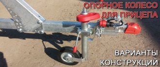
The support stand, also known as the support leg or outrigger, has a number of positive functions. Yes, with its help it will not be possible to make a turn, as is the case with the support wheel. But the support is also intended for slightly different tasks.
Why do you need an outrigger?
Some trailer owners do not fully understand what a support stand is used for and what it can provide as an additional component.
Therefore, it is worth starting by studying this issue.
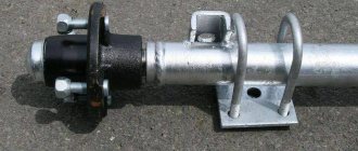
The trailer support stand is designed to provide stability for transporting goods on uneven surfaces. Typically, such elements are installed in the rear. This immediately makes it clear that the support legs are not analogous to the support wheel. The latter is placed in the front part, on the drawbar. As for outriggers, they are often mounted in the amount of 2 pieces along the edges of the rear part of the trailer. This makes it possible to increase stability when heavy loads are transported, loaded and unloaded, and ramps are used for the entry and exit of various equipment.
The outrigger also protects the trailer coupling head from accidental damage. When the rear end is loaded, a strong load in the form of lift is applied to the coupling head.
If it exceeds the permissible values, the head structure may simply collapse. The outrigger prevents this from happening.
Second life of a car
Motorists who are partial to technical creativity are thinking about creating a car-style trailer. To realize the idea, used cars are used that have kept the rear or front part intact. But it so happens that trailers made from cars, or more precisely, from the front of them, do not look aesthetically pleasing. Therefore, in order for the towed unit to look like a rhythmic continuation of the figure of the car, it should be constructed exclusively from the rear part of the vehicle, leaving the front flat and laconic, or even just the rear part of the trailer.
Design options
Nowadays, it is not difficult to buy a support stand for yourself. In Russia, racks manufactured by Al-Ko are widely used, which are often equipped with trailers from the factory.
Among Al-Ko's partners we can highlight such manufacturers as SST or one of the largest companies MZSA.
If we distinguish varieties, then outriggers can be divided into 2 large groups.
Towbar
Rice. 3 Ball-type towing device
: 1 - oiler, 2 - glass, 3 - spring, 4 - lever axis (M12 bolt with washer, cotter pin and castle nut), 5 - stopper (steel pin d 10 with locking pin), 6 - lever with thrust fist ( steel plate s15), 7 - safety pin, 8 - coupling body (steel pipe d 60 - 80), 9 - ball coupling element (ball d 50, landing cone 1:20), 10 - bracket for the coupling device on the towing vehicle .
Which trailer can be towed with category C?
- Homemade. A do-it-yourself support is usually made from scrap materials, and not always of high quality. Practice shows that an old jack is used as a basis. But there are still many questions about quality and reliability;
- Factory ones. Preference should be given to factory-made components for trailers. Especially if it's Al-Ko level quality. Galvanized coating, reliable and durable mechanisms.
But the choice is still yours to make.
You can make a drawing and use it to assemble and weld the support. What kind of homemade stand you get depends only on your skills and the materials used.
Separately, it is worth highlighting the presence of rotary clamps. They are practical and functional. But it all depends on your needs when operating a trailer with a support leg. Some people don't need this.
The most popular version is the telescopic jack support for caravans. The screw design, which has its own advantages, is no less common. But screw elements require more careful care, since the threads can gradually become dirty and the edges can peel off during active use and in the case of low-quality material. As for telescopic models, rotation here is quite easy, using the built-in or included handle.
Depending on the design features of the outriggers, installation is carried out accordingly.
Now a little about the installation of supporting structures.
Operating a homemade trailer
Volvo car with trailer from the back
As for the legal operation of a trailer from the back of a damaged car, GOST rules provide for technical requirements, and the registration procedure requires additional examination in an accredited laboratory. Such a device is an extraordinary trailer. The initial technical inspection will be carried out with the enthusiasm of the inspector.
Is it necessary to register?
As for the obligation to register a homemade trailer, all vehicles, including those made by hand, are required to undergo state registration. A trailer from the back of a vehicle is no exception. Therefore, it is worth taking care of preparing all the necessary papers and documents in advance. It is worth noting that the towbar also requires mandatory registration, in the absence of which a fine of 500 rubles is imposed on the owner. To register a homemade vehicle, you need to collect some documents; read this article about what documents to collect and how to register a trailer.
What happens when driving with a homemade trailer without registration?
If a car owner has constructed a trailer from the back of a car, but has not taken care to register it in a timely manner, sooner or later he will receive sanctions from law enforcement officers in the form of a fine. The fine varies from 500 to 800 rubles for driving an unlicensed vehicle. A repeated violation will be punished in the amount of 5,000 rubles or in the form of deprivation of a driver’s license for up to three months. And also when using false numbers, deprivation of rights is also applied.
Video about making a trailer from the back of a Lada Priora
It’s hard to disagree that using an old car body is quite an interesting and original activity.
Cruise control in a car: principle of operation, how to install it yourself
- The racks are mainly mounted on top of the attachment to the trailer platform, or on the side;
- If installation is performed from above, you will additionally need to drill 2 holes;
- If the rack is installed from the factory, then the trailer will have corresponding mounting holes;
- If there are no such holes, there is nothing to worry about. You just have to make them yourself. Or entrust this work to specialists;
- When operating a trailer with a high platform, where the ground clearance is about 45-50 centimeters, a lower mounting of the support post can be used;
- Various outriggers are usually designed for installation on certain types and models of trailers, if we talk about Al-Ko.
In general, there is no need to worry about installation. To begin, choose a rack with a clamp and mounting hardware that fits your trailer. Next, the manufacturer will provide you with detailed instructions. Or specialists can take on this work themselves. Typically, the cost of installation does not exceed 1000 rubles for 1 outrigger. And this is provided that you need to make mounting holes.
That's all for me. Thank you all for your attention. Expect a lot of new, useful and interesting materials soon.
Subscribe, leave comments, ask questions and tell your friends about our project!
Cabin seats and cushioning
If the springs are damaged, they must be repaired or replaced with new ones. To do this, you will need to remove the seats using a set of wrenches and screwdrivers. If only one spring fails, then you can install an additional shock absorber or replace the spring torsion bar with an imported part. This will increase driver comfort while the vehicle is moving. For the same purposes, the depreciation system can be improved. For this purpose, half springs from the latest KamAZ models are suitable, which are supplied along with the necessary fastenings.
To install new springs and reinforced suspension, you will need to completely dismantle the rear clamp securing the driver's cab, remove the clamp control handle, remove the locking lock and mounting brackets.
After this, you can proceed to installing a new shock absorber by placing it on the support frame. You need to lower the latches with the fastener, slightly sawing off the mudguard from the inner surface of the wing. The cabin should be installed on a wooden or iron stand and brackets should be installed. Then you need to install all the fasteners in place. Using a drill, you need to make several holes for the new mechanism and completely secure the shock absorbers using M40 bolts. Care must be taken to ensure that the drill does not pass through the rear motor support mounting bracket.
Such tuning will help increase the driver’s comfort level while performing work.
Design and operation of trailer brake drive devices for KamAZ-5320 and Ural-4320 vehiclesThe trailer brake drive is combined - two-wire and single-wire.
The two-wire drive of the trailer brakes (see Fig. 7.2, lines L and C) includes: a trailer brake control valve 28 with a two-wire drive, a single safety valve 29, two disconnect valves 31, two connecting heads 33 of the “Palm” type.
The trailer brake control valve with a two-wire drive operates in the presence of two autonomous connecting lines - supply and control. It consists of three sections (Fig. 7.20): the lower one (pin I) operates when the front axle wheel brake drive circuit of the service brake system is operating; upper (pin III) - when the brake drive circuit of the wheels of the rear bogie of the service brake system is operating; middle (pin II) - when the brake drive circuit of the parking or spare brake systems is operating. In addition, in the middle section there are two more terminals, terminal V is connected to the air cylinder of the parking and spare brake systems; terminal IV - with a control line for a two-wire drive and a trailer brake control valve with a single-wire drive.
The valve controls the trailer brakes - supplies compressed air from the source (pin V) to consumers (pin IV) - with three independent commands acting simultaneously and separately; at the same time to conclusions I
, III a direct action command is sent (to increase the pressure when air is supplied by a two-section brake valve), to terminal II - a reverse action command (to reduce the pressure when air is released by a manual brake valve).
The main parts of the valve are: upper 5, middle 13 and lower 15 body (sections); large 6 and small 9 upper pistons with their own springs 10 and 8, respectively; middle piston 12 s
inlet valve 4, constantly pressed by a spring to the piston seat, and rod 14; exhaust valve 11; unloading hole 3.
In the braked position (Fig. 7.20, b), compressed air is constantly supplied to terminals II and V, which, acting on the diaphragm from above / and from below on the piston 12, holds the rod 14 together with the piston 72 in the lower position, since the area of the diaphragm is larger than the area piston In the upper part of the body, pistons 6 and 9, under the action of spring 10, are in the uppermost position and the exhaust valve 11 is torn off from the seat made in the valve
4, and the inlet valve 4 is closed under the action of spring 2. In this case, terminal IV connects the trailer brake control line with atmospheric terminal VI through relief holes 3 of the valve and rod.
When braking (Fig. 7.20, c), compressed air from the brake valve sections is supplied to terminals I and II. Under the action of compressed air supplied to terminal I, rod 14, together with the middle piston 12 and valve 4, moves upward. Compressed air supplied to terminal III moves the upper pistons 6 and 9 down, compressing the spring 10. In this case, the exhaust valve 11 sits in the valve seat 4, disconnecting terminal IV from the atmospheric terminal VI, and then lifts valve 4 from the seat of the middle piston 12.
Compressed air from terminal V, connected to the air cylinder, flows to terminal IV and further into the trailer brake control line until the force from the air pressure on piston 9 from below is balanced by the force acting on piston 9 from above, developed by the compressed air pressure and springs 8, and the force from the air pressure on the middle piston 12 is not balanced by the force from the air pressure acting on the diaphragm 1 from below, i.e., a tracking action is carried out.
When the brake is released (Fig. 7.20, b), compressed air is removed from terminals I and III through an atmospheric hole in the brake valve. Pistons 6 and 9, under the action of spring 10 and compressed air, occupy the upper position, rod 14 with piston 12 occupy the lower position. Valve 11 is detached from valve seat 4 and communicates terminal IV with atmospheric terminal VI.
When compressed air is supplied to terminals I or III separately, the rod 14 with the piston 12 moves upward, or the large 6 and small 9 pistons move downwards. Braking and debraking occurs in the same way as already described. When braking with the spare or parking brake system of the car (Fig. 7.20, d), compressed air from outlet II through the atmospheric hole in the manual reverse-action brake valve is released into the atmosphere. The pressure above the diaphragm 1 drops and thereby the force acting on the diaphragm and with it on the rod 14 and piston 12 from above decreases. Under the influence of constant pressure of compressed air supplied to terminal V, piston 12 together with rod 14 moves upward. In this case, valve seat 4 rests on valve 11, disconnecting terminal IV from the atmosphere, and then valve 4 is torn off from piston seat 12 and terminal IV communicates with terminal V. Compressed air enters the controlled line of the trailer.
The pressure in the trailer brake control line increases until the force acting on piston 12 from below is balanced by the force acting on diaphragm 1 and piston 12 from above, which ensures the follower action of valve 4.
When supplying compressed air to terminal III or simultaneously to terminals III and I, the pressure in terminal IV connected to the trailer brake control line exceeds the air pressure,
connected to terminal III by 20–100 kPa (0.2–1.0 kgf/cm2), which ensures the leading action of the trailer (semi-trailer) brakes. The excess pressure is regulated by screw 7 (Fig. 7.20, a): when the screw is screwed in, the excess increases, when turned out, it decreases.
Window shelf.
#1 Starkov » February 12, 2014, 6:54 am
Friends, does anyone have the dimensions of an acoustic shelf for a low KamAZ roof? preferably a sketch in a photo or a link
?
Re: Acoustic shelf (low roof)
#2 Vanya » February 18, 2014, 13:40
Re: Acoustic shelf (low roof)
#3 Starkov » February 18, 2014, 2:18 pm
Re: Acoustic shelf (low roof)
#4 Vanya » February 18, 2014, 7:10 pm
Re: Acoustic shelf (low roof)
#5 Starkov » February 18, 2014, 20:18
Re: Acoustic shelf (low roof)
#6 Sasha87 » February 18, 2014, 20:47
Re: Acoustic shelf (low roof)
#7 tree » February 18, 2014, 10:21 pm
Re: Acoustic shelf (low roof)
#8 Sasha87 » February 18, 2014, 10:38 pm
Re: Acoustic shelf (low roof)
#9 tree » February 18, 2014, 11:15 pm
Re: Acoustic shelf (low roof)
#10 Sasha87 » February 18, 2014, 11:22 pm
Re: Acoustic shelf (low roof)
#11 Starkov » February 19, 2014, 14:20
Re: Acoustic shelf (low roof)
#12 Starkov » February 19, 2014, 2:22 pm
Re: Acoustic shelf (low roof)
#13 Starkov » February 19, 2014, 14:23
Re: Acoustic shelf (low roof)
#14 Starkov » February 19, 2014, 14:25
Re: Window shelf.
#15 lenchik » February 19, 2014, 20:51
Re: Window shelf.
#16 Starkov » February 20, 2014, 2:11 pm
[quote=”little tree”]since you do it yourself, the main thing is that the width is not too large, and so, in principle, you take a piece of siding and adjust it as you like, and then transfer the dimensions onto the chipboard and everything is ok.
Lenchik, thanks for the advice. Already in the process of production))
Re: Window shelf.
#17 Pretzel » February 20, 2014, 6:39 pm
Re: Window shelf.
#18 Sasha87 » February 21, 2014, 1:47
Re: Window shelf.
#19 Vanya » February 21, 2014, 11:59
Re: Window shelf.
#20 Sasha87 » February 21, 2014, 21:22
Re: Window shelf.
#21 [email protected] » February 22, 2014, 8:07 pm
Re: Window shelf.
#22 Sasha87 » February 22, 2014, 8:48 pm
Salon
The interior decoration of the KamAZ-5490 can be carried out to the extent that the driver needs to feel comfortable inside the cabin. The moral and physical condition of the driver during the trip depends on the comfort of being in the car.
You can perform tuning with your own hands in the following areas:
- Finishing of the internal surface with special materials that absorb noise and vibration, creating an effective thermal insulation layer. It is better to upholster (upholster) the interior with fabric that is easy to clean and does not absorb dust.
- Installation of a new comfortable chair with air suspension, settings and armrests. For upholstery, it is better to use natural materials (leather, suede, tarpaulin) or their synthetic analogues (Alcantara, denim). With such a change it will be convenient even in the KamAZ “Selkhoznik”, which has a minimum set of amenities.
- Making an extra bed. This option is necessary for model 6520 and similar ones, when there is a need to rest directly in the car. The shelf is removable or folding with double folding.
- Installation of an upper shelf for personal belongings, spare parts and documentation. Considering the height of the KamAZ-53212 cab, the shelf can be made high, with several partitions, doors or sides. After installation, the shelf is upholstered to match the interior decoration or made in a contrasting color.
- Replacing the steering block. A part is installed with the ability to adjust the length and tilt of the column. The wheel is covered with smooth or textured material. A useful addition is the installation of a unit with an airbag.
The lighting system plays an important role during travel and relaxation. Using LED lamps of various wattages, bright, outdoor and emergency lighting is created.
Selection of materials for the blade
When making a snow blade, you can use metal barrels (200 liters in volume).
They have proven themselves long ago, and it is recommended to use at least two barrels to strengthen the structure. To guide and strengthen the shovel, it is better to use square or rectangular pipes, as well as a thin channel and I-beams. Remember that your blade needs to be strengthened, but taking into account possible overload.
The mechanism for adjusting the angles of inclination of the snow plow can be made from pipes of different diameters. In order to control the blade from the cabin, you will need a winch and a system of fixing units, which also requires additional costs for materials.
Conversion to starter starting according to the version of the manufacturer MTZ
Everyone knows that the components and parts of modifications of MTZ 80(82) tractors are maximally unified and interchangeable. Therefore, the alteration consists of installing on the tractor components and parts from the manufacturer’s plant that correspond to the MTZ 80(82) starting system with electric starter. This option is considered the most expensive and time-consuming, but fully corresponds to the manufacturer’s configuration with this starting system.
Parts and components for conversion to a starter
1 Rear engine plate for mounting the starter.
The part is replaced due to the different location of the mounting holes for fastening the units transmitting rotation to the ring gear with a starter or starter. Also, in order not to completely replace the part, you can get by with a commercially available fragment of a plate for fastening the starter, which is installed with an overlay from the outside in the place where the starter transmission housing is mounted. This ensures the correct location of the starter Bendix drive gear for full engagement with the diesel flywheel.
Factory conversion kit for MTZ 80
2 Replacing the flywheel.
Why do you need to replace the flywheel? — For drive from a starter, the ring gear of the part has a smaller size in terms of the internal landing diameter and the outer diameter, so it is impossible to simply replace the rings without changing the flywheel completely.
For reference: the crown for the starter of the D-240, D 243, D 245 engines has 145 teeth. The D-240 crown for a 119-teeth launcher, accordingly, has a wider tooth base and completely different engagement parameters.
To complete the description of the conversion process according to the factory version, we list the sequence of operations:
- The starting motor with the clutch reducer is dismantled.
- The outlet windows of the cooling jacket in the diesel unit for supplying liquid to the starting engine are plugged.
- Roll out the tractor, disconnecting the diesel engine from the housing of the intermediate part of the tractor transmission.
- Remove the clutch basket, remove the flywheel, dismantle the rear plate if it is completely replaced under the starter.
- Assembly is carried out in the reverse order, installing the flywheel with the crown under the starter.
- Install the starter into the seat in the replaced plate or through a fragment of the plate.
About choosing a starter! For a reliable MTZ 80(82) starting system, it is recommended to install a 3.5 kW starter from trusted manufacturers with a reinforced gearbox and housing.