KamAZ is the undisputed leader of the Russian automotive industry and a prominent participant in the global market of truck manufacturers. Over the years of operation, the company has produced more than 2.24 vehicles. Various KamAZ models occupy almost half of the domestic truck market, and the company is in 16th place in the world ranking of truck manufacturers.
The basis of the KamAZ model line are trucks equipped with a turbocharged diesel engine. The cars produced today are equipped with the most advanced Common Rail fuel injection system. A mandatory element of diesel power units is a high-pressure fuel pump, or, as it is often abbreviated, injection pump. The purpose of this article is to describe the features of the KamAZ fuel injection pump, the principle of its operation and functional purpose, as well as the design and rules of maintenance and diagnostics.
Purpose
The functional purpose of KamAZ fuel injection pumps does not differ from standard high-pressure fuel pumps used in diesel engines. It consists of solving several key problems:
· movement of fuel to nozzles connected to combustion chambers;
· pumping fuel pressure to the level necessary for its self-ignition;
· dosage of diesel fuel, ensuring engine efficiency and the most complete combustion of fuel;
· determination of the optimal time for fuel injection into the combustion chambers;
· cleaning of fuel during its transportation.
The fuel injection pump of any diesel engine plays an extremely important role for the operation of the entire power unit. It was the invention and gradual improvement of high-pressure fuel pumps that led to the fact that diesel units using diesel fuel first successfully competed, and then simply began to outperform engines designed to use gasoline.
It is important to note a feature that is typical specifically for trucks, the class of which includes all KamAZ models. We are talking about the need to develop serious power, combining it with efficiency and environmental friendliness in work. The use of fuel injection pump and a modern common rail fuel injection system allows us to successfully solve the problem, which, along with the affordable cost, is an important competitive advantage of the products of the Kama Automobile Plant.
Vehicle power system design
As they say, power systems and electrical equipment are the most susceptible to malfunctions. Since you are faced with malfunctions of the KAMAZ injection pump , let's choose the most suitable KAMAZ injection pump model for your car. To do this, you should study the technical characteristics of the KAMAZ injection pump.
First of all, let's look at the injection pump 33-02, 334, 332-30, 337-80.01 of the KAMAZ-740 engine
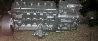
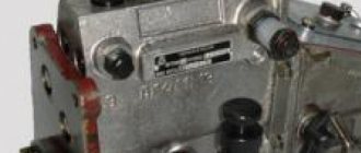
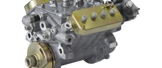
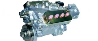
Fuel injection pump KAMAZ 740 models 33-02, 3310, 334, 332-30, 337-80.01 are high-pressure fuel pumps with a V-shaped arrangement of sections and a distance between sections of 36 mm.
KAMAZ 740 fuel pumps models 33-02, 33-10, 334, 337-80.01 include a mechanical all-mode regulator and corrector.
The fuel injection pump KAMAZ 332-30, unlike previous models, has a mechanical dual-mode regulator with correctors (direct and reverse). KAMAZ engines, which are equipped with the following fuel injection pump models, comply with EURO-0 toxicity standards. If any problems occur with the engine or the engine runs unevenly, this is a sign of a malfunction of the KAMAZ injection pump.
Technical characteristics of fuel injection pump KAMAZ 740
| Injection pump model | Number of fuel injection pump sections | Diameter/maximum stroke of plunger (mm) | Nozzle model | Engine model KAMAZ 740 | N nom. (hp) at n (min -1) | Where is the injection pump 332-30 |
| 33-02 | 8 | 9/10 | 33-02 | 740.10 | 210/2600 | KamAZ: 5320, 5410, 5511, 54112, 55102, 4310, 43101; URAL-4320, ZIL-133GYA |
| 33-10 | 8 | 9/10 | 271-01 271-02 | 740.10-20 | 220/2600 | KamAZ: 43101,4326, 54112, 55111, 5320, 5410, 53213,53202,431017, 551107, 55102, 551027, 541007, 551117, 431017; URAL 43207; ZIL-133GYA |
| 334 | 8 | 9/10 | 271-01 271-02 | 7403 | 260/2600 | KamAZ: 43114,4326-01, 43118-01, 53228-01, 55111-01, 43101-01, 53229-01, 53212-01, 54112-01, 53211-01, 53213-01; GAZ-5903 |
| 332-30 | 8 | 10/11 | 272-02 | 7408.10 | 195/2200 | LiAZ-5256 |
| 337-80.01 | 8 | 10/11 | 273-21 | 740.14-300 | 300/2600 | Specialist. cars |
Technical characteristics of fuel injection pump 337-20 engine
KAMAZ-740 EURO2 standard
The fuel injection pump KAMAZ 740 337-20 is a high-pressure fuel pump that has a V-shaped arrangement of sections with a distance between sections of 36 mm.
The KAMAZ 337-20 injection pump produces fuel injection pressures of up to 1200 Bar. kit 337-20 includes an all-mode mechanical regulator with reverse and direct corrector, as well as a boost corrector. Moreover, these engines comply with the EURO-2 standard. Production of engines with fuel injection pump 337-20 began in September 2002.
Technical characteristics of fuel injection pump 337-20 engine
KAMAZ 740 EURO 2
| Injection pump model | Number of fuel injection pump sections | Diameter/maximum stroke of plunger (mm) | Nozzle model | Engine model | N nom. (hp) at n (min -1) | Where is the injection pump 337-20 |
| 337-20 | 8 | 11/13 | 273-21 | 740.30-260E2 | 260/2200 | EURO-2 KamAZ-65115, 65116, 65117, 6540 |
| 337-20.03 | 8 | 11/13 | 273-20 | 740.51-320E2 | 320/2200 | EURO-2 KamAZ-6520, 6522 |
| 337-20.04 | 8 | 11/13 | 273-20 | 740.50-360E2 | 360/2200 | EURO-2 KamAZ- 6360-06, 6460-06, 5360-06, 5460-06 |
Technical characteristics of fuel injection pump 337-40, 337-70 engine
KAMAZ-740 EURO-1
The injection pump 337-40 KAMAZ 740 is a high-pressure fuel pump, which is equipped with sections with a V-shaped arrangement and has a distance between sections of 36 mm. The fuel injection pump 337-40 is equipped with a regulator with two modes, as well as a direct and reverse corrector. Produced since 1995.
| Injection pump model | Number of fuel injection pump sections | Diameter/maximum stroke of plunger (mm) | Nozzle model | Engine model | N nom. (hp) at n (min -1) | Where is the injection pump 337-40 |
| 337-40 | 8 | 11/13 | 273-30 273-31 | 740.11-240E1 7405.10 | 240/2200 240/2200 | EURO-1 KamAZ-55111-02, 65115, 53212-02, 54112-02, 54115, 53215, 53205-02, 53213, 53202, 53229-02, 54105-02, 53228-02, 4326, 4350 . |
| 337-40.01 | 8 | 11/13 | 273-31 | 740.22-240 | 240/2000 | Rules 96 Combine “Don-1500” |
| 337-40.02 | 8 | 11/13 | 273-31 | 740.02-180 | 180/2200 | Rules 96 Tractors T-150K, HTZ-170, IFA feed chopper |
| 337-70 | 8 | 11/13 | 273-31 | 740.11-240 | 240/2200 | Buses: NefAZ-5297, PAZ-5272, LiAZ-5256 |
Technical characteristics of fuel injection pump 337-42 engine
KAMAZ-740 EURO-1
The injection pump 337-42 is a high-pressure fuel pump, which is equipped with sections with a V-shaped arrangement and has a distance between sections of 36 mm. The injection pump 337-42 is equipped with a mechanical all-mode regulator, as well as a direct and reverse corrector. Produced since 2002.
| Injection pump model | Number of fuel injection pump sections | Diameter/max. plunger stroke (mm) | Nozzle model | Engine model | N nom. (hp) at n (min -1) | Where is fuel injection pump 337-42 |
| 337-42 | 8 | 11/13 | 273-20 | 740.13-260 | 260/2200 | EURO-1 KamAZ-43118, 44108, 65111, 6540 |
| 337-42.01 | 8 | 11/13 | 273-20 | 740.22-240 | 240/2000 | Rules 96 Combine “Don-1500” |
Device
Different KamAZ models use different fuel injection pump modifications. Most of the trucks produced by the plant use double-row V-shaped injection pumps, consisting of 8 sections arranged four in a row. They belong to direct-acting fuel pumps, the operating principle of which involves mechanical interaction directly with the crankshaft.
The KamAZ fuel injection pump design provides for the following parts, parts and assemblies:
· fuel pump housing, inside which the remaining elements of the mechanism are located;
· the main working unit of the injection pump in the form of a plunger pair located in each section;
· springs that ensure the movement of the piston inside the cylinder and transmit the energy of the cam mechanism to the plunger pushers;
· the plunger pushers themselves;
· fuel injection and drain fittings;
· an electromagnetic type valve designed to shut off fuel injection;
· electronic sensors and control and monitoring devices for fuel injection pump operation.
It is the diverse electronics that ensure the high efficiency of the Common Rail fuel injection system and the diesel engine equipped with it as a whole. Thanks to the automatic operation, an economical operating mode of the fuel system is ensured, fuel consumption is reduced and its maximum complete combustion is achieved, reducing harmful emissions into the atmosphere. The above fully applies to KamAZ fuel injection pumps, which are installed on trucks of currently produced models.
Principle of operation
The KamAZ injection pump provides a standard operating scheme. It includes the following stages:
1. Mechanical transmission of energy from the crankshaft to the camshaft.
2. Rotation of the latter, which triggers the movement of the pushers, moving the plunger with the help of springs and its own movement from its original position in the lower part of the sleeve to its upper part.
3. The piston closes the intake valve and builds up pressure in the space above the plunger.
4. The injector valve operates and sprays fuel inside the combustion chamber under pressure sufficient for self-ignition.
5. Draining excess fuel and moving the plunger to its original position, resulting in the opening of the inlet valve and starting a new operating cycle.
As the above description shows, the operating principle of the KamAZ injection pump is standard for any high-pressure fuel pump of a diesel engine. This is quite logical, since the main requirements for such a mechanism are reliability and durability. It is to ensure these parameters that in the manufacture of individual parts of the injection pump and, above all, the plunger pair, high-strength alloy steels are used, and the parts themselves - the piston and bushing - are carefully processed and ground to each other, thereby achieving the required level of tightness of the entire assembly.
_______________________________________________________________________________
Kamaz-740 diesel fuel system and its components
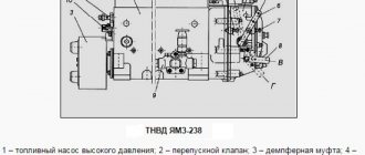
The fuel supply system (fuel system) of KamAZ-740 ensures fuel purification and its uniform distribution among the engine cylinders in strictly metered portions. Kamaz-740 engines use a split-type fuel supply system, consisting of a high-pressure fuel pump, injectors, coarse and fine filters, a low-pressure fuel booster pump, low- and high-pressure fuel lines, fuel tanks, a solenoid valve and flare spark plugs for an electric torch starting device. A schematic diagram of the Kamaz-740 fuel system is shown in Fig. 1. Fuel from tank 1 through a coarse filter 2 is sucked in by the fuel priming pump and through a fine filter 17 through low pressure fuel lines 3, 9, 15, 21 and supplied to the high pressure fuel pump; According to the operating order of the engine cylinders, the pump distributes fuel through high-pressure pipelines 6 to injectors 5.
Rice. 1. Diagram of the fuel system of the Kamaz-740 engine 1 - fuel tank; 2 — fuel coarse filter; 3-fuel pipe supplying the low pressure pump; 4 — fuel drainage pipe of the left head injectors; 5 - nozzle; 6 — high pressure fuel pipe; 7 — low pressure fuel priming pump; 8 — manual fuel priming pump; 9 — fuel outlet pipe of the low pressure pump; 10 — high pressure fuel pump; 11 — electromagnetic valve; 12-fuel pipe to the solenoid valve; 13 — torch candle; 14 — fuel drain pipe for right-hand injectors; 15 — fuel injection pipe; 16 — fuel outlet pipe of the injection pump; 17 — fine fuel filter; 18 — fuel fine filter tube; 19 — tee for fastening fuel pipes; 20 — fuel drain pipe; 21 – fuel line to the coarse filter; 22 - receiving pipe with filter Kamaz-740 injectors spray and inject fuel into the combustion chambers. Excess fuel, and along with it the air that has entered the Kamaz-740 fuel system, is discharged into the fuel tank through the bypass valve of the high-pressure fuel pump and the fine filter nozzle valve through fuel drain lines 16 and 18. The fuel that has leaked through the gap between the nozzle body and the needle is drained into the tank through fuel drain lines 4, 14, 20. The Kamaz-740 coarse filter (sump) (Fig. 2) pre-cleanses the fuel entering the low-pressure fuel priming pump. Rice. 2. Coarse fuel filter Kamaz-740 1 – plug; 2 – glass; 3 – pacifier; 4 – filter mesh; 5 – reflector; 6 – distributor; 7 – bolt; 8 – flange; 9 – sealing ring; 10 – housing The coarse filter is installed on the suction line of the Kamaz-740 power system on the left side of the vehicle on the frame. Glass 2 is connected to housing 10 with four bolts 7 and sealed with ring 9. A drain plug 1 is screwed into the bottom of the cap boss. The fuel coming from the fuel tank through the supply fitting flows into the glasses. Large particles and water collect at the bottom of the glass. From the upper part, through filter mesh 4, fuel is supplied to the fuel priming pump through the outlet fitting and fuel lines. The Kamaz-740 fine filter (Fig. 3), which finally cleans the fuel before entering the high-pressure fuel pump, is installed at the highest point of the Kamaz-740 power system to collect and remove into the tank the air that has entered the power system along with part of the fuel through the valve - jet installed in housing 1. Fig. 3. Fine fuel filter Kamaz-740 1 – housing: 2 – bolt; 3 – sealing washer; 4 – plug; 5, 6 – sealing gaskets; .7 – filter element; 8 – cap; 9 – filter element spring; 10 – drain plug; 11 – rod The beginning of the shift of valve-nozzle 4 (Fig. 4) occurs at a pressure in the cavity of 24.5 ... 44.1 kPa (0.25 ... 0.45 kgf/cm2), and the beginning of fuel bypass from cavity A to cavity B - at pressure in cavity A is 196.2... 235.3 kPa (2.0... 2.4 kgf/cm2). The valve is adjusted by selecting adjusting washers 1 inside the valve plug.
Rice. 4. Valve-nozzle of fine fuel filter KamAZ-740 1 - adjusting washer; 2 — valve plug; 3-spring; 4 - jet valve Kamaz-740 fuel lines are divided into low pressure fuel lines of 392... 1961 kPa (4... 20 kgf/cm2) and high pressure of more than 19614 kPa (200 kgf/cm2). The high-pressure fuel lines of the Kamaz-740 fuel system are made of steel tubes, the ends of which are made cone-shaped, pressed with union nuts through washers to the conical sockets of the fuel pump fittings and injectors. To avoid damage from vibration, the fuel lines are secured with brackets and brackets. Fuel injection pump Kamaz-740 The high-pressure fuel pump (HPF) Kamaz-740 is designed to supply strictly dosed portions of fuel under high pressure to the engine cylinders at certain times. Eight sections are installed in the Kamaz-740 injection pump housing (Fig. 5), each consisting of a housing 17, a sleeve 16 of a plunger 11, a rotary sleeve 10, a discharge valve 19, pressed through a sealing gasket 18 to the plunger sleeve by a fitting 20. The plunger performs a reciprocating movement under the action of the cam shaft 44 and spring 8. Fig. 5. Fuel pump Kamaz-740 injection pump 1 - housing; 2, 32 — pusher rollers; 3, 31 — roller axes; 4 - roller bushing; 5 — pusher heel; 6 - cracker; 7 — pusher spring plate; 8 — pusher spring: 9,34,43,45, 51 — washers; 10 — rotary bushing; 11 - plunger; 12, 13, 46, 55 — sealing rings; 14—locating pin; 15 - rack; 16 — plunger bushing; 17 — section body; 18 — discharge valve gasket; 19 - discharge valve; 20 - fitting; 21 — section housing flange; 22 — manual fuel priming pump; 23 — spring plug; 24, 48 — gaskets; 25 - low pressure pump housing; 26 — low pressure fuel priming pump; 27 — rod bushing; 28 — pusher spring; 29 — pusher; 30 — locking screw; 33, 52 — nuts; 35 — low pressure pump drive eccentric; 36, 50 — keys; 37 — flange of the regulator drive gear; 38 — holder of the regulator drive gear; 39 — regulator drive gear; 40 — thrust bushing; 41, 49 — bearing caps; 42 — bearing; 44 — cam shaft; 47 — cuff with spring assembly; 53 — fuel injection advance clutch; 54 — rack plug; 56 — bypass valve; 57 — rack bushing; 58 — rack lever axis; 59 — adjusting shims The pusher is secured against rotation in the body of the Kamaz-740 injection pump fuel pump by a cracker 6. The cam shaft rotates in roller bearings 42 installed in the covers and attached to the pump body. The axial clearance of the cam shaft is adjusted by shims 48. The clearance should be no more than 0.1 mm. To increase the fuel supply, the plunger 11 is rotated by a sleeve 10 connected through the axis of the driver to the pump rack 15. The rack is mixed in the guide bushings 57. Its protruding end is closed with a plug 54. On the opposite side of the Kamaz-740 injection pump there is a screw that regulates the fuel supply to all sections of the pump. This screw is capped and sealed. Fuel is supplied to the Kamaz-740 high-pressure fuel pump through a special fitting, to which a low-pressure pipe is bolted. Then, through the channels in the body, it flows to the inlet holes of the 16 plunger bushings. A bypass valve 56 is installed at the front end of the Kamaz-740 fuel injection pump housing and at the fuel outlet, which opens at a pressure of 58.8... 78.5 kPa (0.6... 0.8 kgf/cm2). The valve opening pressure is regulated by selecting shims inside the valve plug. The pump is lubricated by circulation, under pressure from the general engine lubrication system. The turbocharged engine is equipped with a Kamaz-740 TNVD 334 fuel pump with increased injection energy, with an anti-smoke corrector and a nominal cyclic fuel supply of 96 mm3/cycle. The rotation speed regulator of the Kamaz-740 injection pump is all-mode, direct-acting, changes the amount of fuel supplied to the cylinder depending on the load, maintaining a given frequency. The regulator is installed in the housing casing of the Kamaz-740 high-pressure fuel pump. The drive gear 21 of the regulator is installed on the cam shaft of the Kamaz-740 injection pump fuel pump, rotation to which is transmitted through rubber nuts 22. The driven gear is integral with the weight holder 9, rotating on two ball bearings. When the holder rotates, the weights 13, swinging on the axes 10, diverge under the action of centrifugal forces and move the clutch 12 through the thrust bearing 11. The clutch, resting against the pin 14, in turn moves the lever 32 of the weight clutch. Lever 32 is fixed at one end to axis 33, and at the other end it is connected through a pin to rack 27 of the Kamaz-740 injection pump. A lever 31 is fixed to the axis 33, the other end of which moves all the way to the fuel supply adjusting bolt 24. Lever 32 transmits force to lever 31 through corrector 15. Fuel supply control lever 1 (Fig. 7) is rigidly connected to the lever. A spring 26 is attached to the levers 20, 31, a starting spring 28 is attached to the levers 25, 30. During operation of the regulator in a certain mode, the centrifugal forces of the loads are balanced by the force of the spring 26. Fig. 7. Cover of the Kamaz-740 speed regulator 1 - control lever for the fuel supply regulator; 2 — bolt for limiting the minimum rotation speed; 3 — stop lever; 4 — filler plug; 5 — starting feed adjustment bolt; 6 — bolt for limiting the travel of the stop lever; 7 — bolt for limiting maximum rotation speed; I - work; II - off When the speed of rotation of the crankshaft of the regulator increases, overcoming the resistance of the spring 26, the weights move the lever 32 of the Kamaz-740 injection pump regulator - the fuel supply decreases. As the crankshaft rotation speed decreases, the centrifugal force of the loads decreases, and the regulator lever 32 with the fuel pump rack moves in the opposite direction under the action of the spring force—the fuel supply and the crankshaft rotation speed increase. The fuel supply is turned off by turning stop lever 3 (see Fig. 7) until it stops against bolt 6, while lever 3, overcoming the spring force, turns levers 31 and 32 through pin 29; the rack will move until the fuel supply is completely turned off. When the force is removed from the stop lever, under the action of the spring, the lever will return to the operating position, and the starting spring 16 through the lever 30 will return the fuel pump rack to the position of the maximum fuel supply required for starting. Low pressure fuel pump and fuel priming pump Kamaz-740 The low pressure fuel pump Kamaz-740 is a piston type designed to supply fuel from the tank through a coarse and fine filter to the inlet cavity of the high pressure pump. The pump is installed on the rear cover of the regulator. A piston, a piston spring, a rod bushing 27 and a pusher rod are installed in the housing 25 (see Fig. 5), and an inlet valve and a valve spring are installed in the housing flange. The eccentric of the cam shaft, through roller 32, pusher 29 and rod, imparts reciprocating movement to the piston of the fuel priming pump. The operating diagram of the Kamaz-740 low-pressure injection pump is shown in Fig. 8. When the pusher is lowered, the piston 10 moves downward under the action of the spring 4. A vacuum is created in suction cavity A, and inlet valve 1, compressing spring 2, allows fuel into the cavity. Rice. 8. Scheme of operation of the low pressure fuel pump and manual fuel priming pump Kamaz-740 1 - inlet valve; 2, 4, 5, 9 — springs; 3 — piston of the manual fuel priming pump; 6 — pusher; 7 - eccentric; 8 — discharge valve; 10 - piston; A - suction cavity; B - injection cavity: C - supply to the fuel injection pump Kamaz-740; E - supply from the fuel coarse filter. At the same time, the fuel located in the discharge cavity B is forced into the main line, bypassing the discharge valve 8, connected by channels to both cavities. In the free position, the discharge valve closes the channel of the suction cavity. When the piston 10 moves upward, the fuel that has filled the suction cavity enters the cavity B under the piston through the discharge valve 8, and the inlet valve 1 closes. When the pressure in the discharge line increases, the piston does not make a full stroke following the pusher, but remains in a position that is determined by the balance of forces from the fuel pressure on one side, and from the spring force on the other side. The Kamaz-740 fuel priming manual pump fills the system with fuel and removes air from it. The piston type pump is mounted on the low pressure fuel pump flange with a copper sealing washer. The Kamaz-740 fuel priming pump consists of a housing, a piston, a cylinder, a handle assembly with a rod, a support plate and a seal. The Kamaz-740 power system is pumped by moving the handle with the rod and piston up and down. When the handle moves upward, a vacuum is created in the sub-piston space. Inlet valve 1, compressing spring 2, opens, and fuel enters cavity A of the low-pressure fuel pump. When the handle moves down, the discharge valve 8 opens and fuel under pressure enters the discharge line. After pumping, screw the handle onto the upper threaded shank of the cylinder. In this case, the piston will press against the rubber gasket, sealing the suction cavity of the low pressure fuel pump. The Kamaz-740 automatic fuel injection advance clutch (Fig. 9) changes the start of fuel supply depending on the engine crankshaft speed. Rice. 9. Automatic fuel injection advance coupling KamAZ-740 1 - driving half-clutch; 2.4 - cuffs; 3 - bushing of the driving coupling half; 5 — body; 6-adjusting gaskets; 7 — spring cup; 8 - spring; 9, 15 — washers; 10 - ring; 11 — weight with a finger; 12 — spacer with axle; 13 — driven coupling half; 14 — sealing ring; 16 - load axis The use of the clutch ensures the optimal start of fuel supply for the work process over the entire range of speed modes. This ensures economy and acceptable rigidity of the process in various speed modes of engine operation. The driven coupling half 13 is fixed on the conical surface of the front end of the cam shaft of the Kamaz-740 fuel pump with a key and a nut with a washer, the driving coupling half 1 is mounted on the hub of the driven coupling half (can be rotated on it). A sleeve 3 is installed between the hub and the coupling half. The weights 11 swing on axes 16, pressed into the driven coupling half, in a plane perpendicular to the axis of rotation of the coupling. Spacer 12 of the drive half of the coupling rests with one end against the load pin, and with the other against the profile protrusion. Spring 8 strives to hold the load against the stop in the sleeve 3 of the drive half-coupling. As the crankshaft rotation speed of the KamAZ-740 increases, the loads diverge under the influence of centrifugal forces, as a result of which the driven coupling half rotates relative to the drive half in the direction of rotation of the cam shaft, which causes an increase in the advance angle of fuel injection. When the crankshaft rotation speed decreases, the weights converge under the action of springs, the driven coupling half rotates together with the pump shaft in the direction opposite to the direction of shaft rotation, which causes a decrease in the fuel supply advance angle. Kamaz-740 nozzle Kamaz-740 nozzle (Fig. 10) is a closed type with a multi-hole nozzle and a hydraulically controlled needle. All nozzle parts are assembled in housing 6. Fig. 10. Kamaz-740 nozzle 1- nozzle body; 2-nozzle nut; 3 — nozzle spacer; 4—locating pins; 5 – nozzle rod; 6 — nozzle body; 7 - sealing ring; 8 - fitting; 9, 10 – adjusting washers; 11 – nozzle spring; 12 A spacer 3 and a spray body 1, inside of which there is a needle, are attached to the lower end of the nozzle body with a nut 2. The body and the atomizer needle form a precision pair. The sprayer has four nozzle holes. Spacer 3 and body 1 are fixed relative to the body with pins. Spring 11 rests against rod 5 at one end, which transmits force to the spray needle, and at the other end - against the stop. Fuel is supplied to the Kamaz-740 injector under high pressure through fitting 8. Then, through the channels of body 6, spacer 3 and body 1 of the nozzle, fuel enters the cavity between the nozzle body and the needle and, squeezing it out, is injected into the cylinder. The fuel that has leaked through the gap between the needle and the nozzle body is discharged through the channels into the nozzle body. The Kamaz-740 injector is installed in the cylinder head and secured with a bracket. The end of the nozzle nut is sealed against gas breakthrough with a corrugated washer. The O-ring protects the cavity between the injector and the cylinder head from dust and water. The turbocharged Kamaz-740 engine has a model 271 injector with increased fuel throughput and a nozzle hole diameter of 0.32 mm. Kamaz-740 fuel supply control drive The Kamaz-740 fuel supply control drive (Fig. 11) is mechanical, with a telescopic pusher, and consists of a pedal, rods, levers and transverse rollers. There is also a manual drive for fuel supply and engine stop. The fuel supply pedal 13 is connected to the speed controller control lever 7. Rice. 11. Kamaz-740 fuel supply control drive 1 - engine stop rod handle; 2 — handle for manual fuel supply control; 3, 10 - rear levers; 4 — rod of the regulator control lever; 5 - injection pump; 6 — engine stop lever; 7-regulator control lever; 8 - transverse roller; 9 — rear bracket; 11- telescopic rod; 12 — pedal bracket; 13 - pedal; 14 - adjusting bolt The handles of the remote control rods of the Kamaz-740 engine are installed in the cab on a bracket at the bottom of the panel: left 2 - to turn on the constant fuel supply, connected by a flexible cable in a protective sheath to the speed control control lever; right 1 - to stop the engine, connected by a cable to the engine stop lever, which is located on the cover of the speed controller.
_______________________________________________________________________________
_______________________________________________________________________________
_______________________________________________________________________________
- Clutch KamAZ-5320 and its components
- Repair of PGU and Kamaz clutch master cylinder
- Gearbox gearbox KamAZ 141
- Gearbox gearbox KamAZ ZF 16
- Gearbox 152 Kamaz with divider
- Gearbox gearbox 154 Kamaz
- Gearbox Kamaz-4308
- Clutch of a Kamaz-4308 car
- Clutch and gearbox KamAZ-65115
- Disassembly and assembly of Kamaz-4310, 55111, 43118 gearboxes
_______________________________________________________________________________
- Cylinder block, head and valves Kamaz-740
- Fuel system of Kamaz-740 diesel engine
- Adjustments and repairs of fuel injection pump Kamaz-740
- Drive axles of the Kamaz-4310 vehicle
- Repair of Kamaz drive axle gearbox
- Rear axle KamAZ-4308
- Axles and suspensions of Kamaz-65115 dump trucks
- Installation of Kamaz cardan shafts and axles
- Repair of Kamaz vehicle transfer case
- Kamaz power steering - adjustments and repairs
- Repair of Kamaz steering gear parts
- Steering parts Kamaz-4308
- Parts of the brake system Kamaz-4308
- Brake system and brake drive Kamaz
- Repair of brake valves and Kamaz compressor
- Suspension Kamaz-4310, 55111, 43118 and their parts
- Frame and suspension of the Kamaz-4308 car
- Cabin details and platform KamAZ-65115
- Cabin components Kamaz-4308
- Platform mechanism of Kamaz vehicles
- Klintsy KS 65719-5K truck crane based on KamAZ-6522 chassis
- Truck crane KC-35719-7-02 based on Kamaz-43118 chassis
- Truck crane Galichanin KC-55713-1K based on KamAZ-65115 6x4
- Ivanovets KS-45717K-1/1R truck crane based on KamAZ-65115 chassis
- Ivanovets KS-3577-3/4 truck crane on KamAZ-43253 4x2 chassis
Main causes of malfunctions
Domestic technology is not among the most reliable and durable. This statement applies least of all to KamAZ, which has long proven in practice the possibility of manufacturing high-quality trucks in Russia. To a large extent, the success of the Kama Automobile Plant's products is explained by the excellent operational and technical properties of diesel engines and the fuel pumps installed on them.
However, even the most reliable and proven equipment periodically becomes unusable. The main reasons for fuel pump failure are:
· water or air in the fuel supply system. This situation arises when using low-quality diesel fuel, with a serious level of wear of the fuel filter, after replacing individual components and parts of the high-pressure fuel pump, as well as insufficient tightness of the system, which results in the formation of internal condensate on the pipelines;
· presence of solid impurities in diesel fuel. In this case, the malfunction also occurs due to a poorly functioning fuel filter, which requires cleaning or replacement;
· low lubricity of diesel fuel. In this situation, we are talking, first of all, about the use of uncertified or low-quality additives, which can lead to failure of the fuel injection pump and the need for an expensive replacement of this important part of the diesel engine;
· lack of tightness of the fuel supply system. The most negative consequences of a malfunction of this type are the entry of air into the plunger pair and increased wear of the piston and cylinder, which inevitably results in expensive repairs and the need to replace worn-out parts.
Repair of fuel injection pump with RQV…K regulators
General description of fuel injection pump assembly
Before assembling the fuel injection pump, it is necessary to wash and troubleshoot it. It is advisable to wash fuel pump parts and injector bodies in drum-type washers operating in a closed cycle. For the last 5 months, the author has been using a Geyser sink with a drum diameter of 700 mm.
Figure 1.1 – Tool kit for installing and fixing the plunger.
When troubleshooting parts of the injection pump and regulator, the author recommends replacing the following spare parts when the plunger pairs are worn:
- 2 418 455 727 – Plunger pair – 8 pcs.;
- 2 418 459 037 – Discharge valve – 8 pcs.;
- 2 414 612 005 – Valve spring – 8 pcs.;
- 2 410 422 013 – Rotating sleeve of the plunger (if there is wear on the ball, look through an 8x magnifying glass);
- 2 417 010 022 – Complete fuel injection pump repair kit;
- 2 427 010 049 – Repair kit for fuel injection pump regulator;
- 2 421 015 057 – Regulator gasket;
- 2 447 010 043 – Repair kit for high pressure fuel pump valves.
Figure 1.2 – Position of the camshaft cams when installing and removing the pusher stops.
When troubleshooting, pay attention to the working surfaces of the cam shaft, pushers, bearings and springs. The injection pump housing must be cleaned; before washing, all rings remaining after dismantling the plunger bushings must be removed.
Figure 1.1 shows the tools for installing the plunger and pusher and fixing the pusher.
The position of the pusher lock is such that the catalog number indicated on the pusher body is located on top, and the 0 mark on the rotating part of the lock is on the bottom. Install and dismantle the pusher stoppers on fully depressed cams in order to prevent breakage of the stoppers.
The cam shaft should be installed as shown in Figure 1.2. Install the cam shaft as shown in Figure 1.3.
Figure 1.3 – Installation of the fuel injection pump cam shaft.
It should be noted that on the fuel injection pump shown in the photo, it is more convenient to dismantle and install the cam shaft from the regulator side. Many models use tapered bearings, so dismantling the cam shaft should be done through the front part of the injection pump after removing the front HF bearing cover.
Dismantling and installation of the cam shaft into the fuel injection pump housing is carried out using a press or with light blows through a copper or aluminum adapter. It is recommended to carry out all impact work with rubber hammers. Use metal plugs only once.
Reasons for diagnosis, maintenance or repair
The simplest and most effective way to ensure long-term and trouble-free operation of KamAZ fuel injection pumps is to regularly undergo diagnostics and maintenance, and, if necessary, repairs by visiting specialized service centers for this. The fact is that independent regulation and any other types of work are not recommended, since a modern fuel pump is a high-tech mechanism equipped with precise and complex electronic automation.
In addition, we should not forget that all KamAZ fuel injection pump settings are interconnected, which makes their adjustment, not to mention maintenance and repair, an extremely complex undertaking that requires both high-precision equipment and specialists capable of using it effectively. The reason for urgently contacting a specialized center for service and maintenance and repair of the KamAZ fuel supply system are the following common problems in the operation of diesel engines:
· differences in power indicators. Experts recommend that in such a situation, urgently adjust the cyclic supply and the fuel injection pump of the vehicle;
Difficulty starting the unit. The causes of the malfunction in this case can be very diverse. To identify them and subsequently eliminate the need, testing the fuel injection pump and the diesel engine as a whole on special stands;
· increased fuel consumption. An extremely unpleasant moment that significantly reduces the level of efficiency when operating the unit on diesel fuel. The cause of the problem is usually the wear of parts and components of the fuel injection pump, so to eliminate the malfunction, their replacement is required;
· extraneous or too loud noise during operation of the power plant. Another reason for urgent diagnostics, adjustment or maintenance of the KamAZ fuel injection pump using modern equipment. This is explained by the fact that there are many potential causes of this problem, which can only be reliably identified during testing on special stands.
Operating rules
In order to minimize the risk of malfunction of the KamAZ fuel injection pump, you must carefully follow several fairly simple recommendations. These include the following rules for operating a cargo vehicle:
1. Use of exclusively high-quality diesel fuel. To do this, you should refuel at proven gas stations.
2. Regular cleaning and, if necessary, replacement of filters installed in the fuel supply system.
3. Regular cleaning and flushing of individual components and parts of the fuel supply system.
4. Use only certified additives and fuel additives after consultation with a specialist.
5. Contact a specialized service center if any problems arise in the operation of the injection pump and KamAZ diesel engine.
6. Regular service and maintenance of both the fuel supply system and the power unit as a whole.
7. Constant monitoring of the tightness of the fuel system of the truck and prompt elimination of detected leaks.
8. Constantly checking the reliability of fastening the injection pump to the diesel engine. If necessary, tighten loose bolted connections.
Adjustment of injection pump series 33 KAMAZ produced by YAZDA
Adjusting the injection pump begins with checking and ensuring the installation dimensions. For the correct kinematic position of the levers when assembling the regulator, it is necessary to set the following initial dimensions (Fig. 5.36): Dimension A - the distance from the mating plane of the pump housing to the head of bolt 29 of the nominal flow; A= 55.5 ±0.2 mm. Dimension B is the distance between the point of application of the spring 11 of the regulator and the generatrix of the axis 6 of the levers, B = 52 ±0.5 mm. To correctly set the size, it is necessary to remove the axis 6 by the cap from the pump body and remove the levers 27 and 28 assemblies. Dimension C is the gap between the limiting nut 32 and the pump housing, C = 0.8+1.0 mm. Dimension O - stroke of the anti-corrector rod 10; O = 0.5+0.6 mm. The spring tightening force is controlled during adjustment. Dimension E—stroke of corrector rod 18; E = 0.6+0.8 mm. The spring tightening force is controlled during adjustment.
Fig. 5.36. Diagram of the KAMAZ speed controller: 1 - starting enrichment spring; 2 — injection pump rack; 3 — axis of levers; 4 — spring adjusting bolt; 5 — bolt of minimum rotation speed; 6,9,13,16,20 - nuts; 7 — regulator spring; 8 — anti-corrector spring; 10 — regulator control lever; 11 — corrector rod; 12 — anti-corrector lever; 14 — bolt of maximum rotation speed; 15 — corrector body; 17 — main lever; 18 — intermediate lever; 19 — nominal feed bolt; 21 — starting feed adjustment bolt; 22 — stop lever; 23 — bolt for limiting the travel of the stop lever.
To check the tightness and opening pressure of the injection valves, fuel is supplied to the injection pump head at a pressure of 0.17+0.2 MPa with the position of lever 22 corresponding to the supply being turned off. Fuel leakage from the fuel injection pump drain pipes is not allowed. Otherwise, if the discharge valve spring is in good condition, replace the discharge valve assembly. Gradually increasing the pressure, observe at what pressure the fuel begins to flow out of the drain pipes. If this value does not fall within the limits of 0.9+1.1 MPa, change the discharge valve spring. Adjustment of the geometric angle of the start of fuel supply begins with determining the shape of the cam profile. The angle of start of fuel supply of an injection pump with a symmetrical profile is determined by the moment the fuel begins to move in a momentoscope connected to the pump fitting. In this case, it is necessary that excess pressure be maintained in the injection pump head within the range of 0.04+0.1 MPa. To check the angle, lever 10 is turned until it stops against bolt 14. A torque scope is installed on the fitting of the eighth section, filled with fuel to the angle of height and the shaft drive is turned in the direction of clockwise rotation. At the moment the fuel begins to move, readings are recorded on a graduated disk. Then turn the shaft drive counterclockwise and again record the readings on the graduated disk at the moment the fuel begins to move in the momentoscope tube. The number of degrees contained between the two divisions obtained on the stand’s graduated disk is divided in half and the average value is found. It must coincide with an accuracy of ±0.35° with the table value of the geometric angle of the start of fuel supply (for series 33 the angle is 42.5° with the exception of 33-02, 335 and 335-10 - 40.5°; 33-10 - 41 ,5°). If the obtained value does not correspond to the table value, adjustment is made by changing the thickness of the plunger pusher heel. In an injection pump with an asymmetrical cam profile (for injection pump models 332, 337), the geometric angle of the start of fuel supply by the first section is estimated by the stroke of the plunger from the beginning of its rise to the beginning of fuel injection. To adjust the angle at which the injection pump begins to supply fuel, it is necessary to unscrew the discharge valve fitting, remove it from the seat and install a special device. By turning the stand drive, determine the lower position of the plunger, then, by rotating the cam shaft in accordance with the direction of rotation, set the plunger stroke corresponding to the table value (for models 332, the plunger stroke is 4.85 ± 0.05 mm; 337 - 5.65 ± 0 .05 mm). The angle value corresponding to this position of the cam shaft is recorded on the calibration disk of the stand. Remove the special device and install the discharge valve, spring, pressure fitting and torque scope. By rotating the stand drive clockwise, fill the momentoscope tube with fuel and find the position of the cam shaft at which the fuel supply begins. The corresponding angle value on the calibration disk must coincide with that previously recorded. If necessary, adjust the angle at which fuel supply begins by changing the thickness of the plunger pusher heel. At the moment the eighth section begins to pump fuel, the discrepancy between the marks on the fuel injection pump housing and the fuel injection advance clutch should not exceed 0.5°. Otherwise, caulk the old mark and apply a new one. Place lever 10 against the stop in bolt 14 and gradually increase the rotation speed of the stand shaft. Through the hole for dismantling the rack, record the moment when rack 2 begins to move, corresponding to the start of the regulator’s operation. If the frequency at which the regulator starts to operate does not match the tabulated data, change the position of bolt 14. Set the nominal speed, turn lever 10 until it stops against bolt 14. Measure the cyclic fuel supply and its uniformity between sections. If the cyclic supply does not correspond to the table values, adjust the fuel supply by turning the pump section flange, having previously loosened the high pressure fuel line nut and the flange mounting nuts. The permissible unevenness of the feed between sections is 5% of the value of the nominal cyclic feed. Check the unevenness of fuel supply across sections at 300 min"1. To do this, set the regulator control lever 10 to a position in which the cyclic feed will correspond to 20-30 mm3/cycle. The unevenness of fuel supply across sections should not exceed 35%. Otherwise, replace the discharge valve and plunger pair. Smoothly increase the rotation speed while lever 10 rests on bolt 14. Complete shutdown of the fuel supply should occur at a frequency of 1490+1550 min"1. Otherwise, replace spring 7 of the regulator and begin the adjustment by setting the start of the regulator's action. Adjust the corrector and anti-corrector with the regulator cover removed. To do this, set the rotation speed of the stand drive to 600 rpm, and press lever 17 against the stop against bolt 19. Check the installed gaps with a feeler gauge O = 0.5+0.6 mm. (between the intermediate lever 18 and the anti-corrector lever 12) and E = 0.6+0.8 mm. (between the main lever 17 and the anti-corrector lever 29). Smoothly increase the rotation speed to 900 min”1, in this case the gap O should disappear, and the gap E should not change. At a rotation speed of 1250 rpm1, levers 19, 27 and 28 must be in contact. Otherwise, change the force of the corresponding spring. Change the tightening force of the corrector spring 15 with nut 13, the anti-corrector spring 8 with nut 9. After adjusting the nuts, tighten the cotter pins. Measure the cyclic fuel supply in the corrector and anti-corrector operating modes. If the table data does not correspond, adjust the stroke of the corrector (by turning the housing 15) or the anti-corrector (with nut 6), respectively. After adjustment, check the nominal cyclic fuel supply. At a drive shaft rotation speed of 100 rpm1, turn lever 10 until it stops against bolt 14. In this case, the fuel supply should be 19.5+21 cm3 per 100 cycles. The starting feed is adjusted using bolt 21, turning it out to increase the feed. If the feed is less than permissible, check the condition of the starting spring 1, the ease of movement of the rack 4. Without changing the position of the lever 10, turn the lever 22 until it stops against the bolt 23. When — = rotation speed of the stand drive is equal to 100+150 min"1, screw the bolt 23 until the feed appears fuel, then turn it out 1 turn and lock it. Check for lack of fuel supply throughout the entire speed range of the injection pump. Release lever 10 until it stops against bolt 5. At a drive shaft rotation speed of 300 min'1, the fuel supply should be about 20 mm3/cycle, while complete shutdown of the fuel supply should occur at a frequency of 380+400 min'1. The adjustment is carried out with bolt 5. Install 3 seals: on the screw of the protective cover of the injection pump sections, the bolt of the regulator cover and on bolt 16 of the maximum speed mode (bolt 23 for limiting the travel of the stop lever).
Copied from the site https://tnvd.net © 2010 — Oleg Soroka
Conclusion
The KamAZ injection pump is an important element of the diesel engine of trucks produced by the Kama Automobile Plant. The operational and technical characteristics of the high-pressure fuel pump largely determine the efficiency and operating efficiency of the entire diesel engine. Therefore, it is not surprising that the plant pays the closest attention to the development and improvement of fuel injection pumps.
A prerequisite for long-term and trouble-free operation of the fuel pump is regular maintenance of a unit that is so important for the operation of the engine and the entire truck. It is best to carry out diagnostics, maintenance and repair work in specialized service centers that have both the necessary equipment in the form of testing stands and a staff of professional and qualified specialists.