Category: UAZ
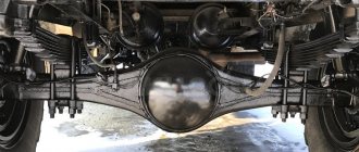
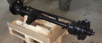
- Rear axle structure of UAZ 469 Carter
- Gearbox
- Half shafts
- Half shafts
- Presence of oil smudges
The UAZ 469 car is used both in the Russian Federation and abroad. The design of the front axle of the UAZ 469 allows you to forcibly engage all-wheel drive. Thanks to this design, the vehicle has high cross-country ability. Below is a description of the 469 axle design.
Front axle UAZ loaf model Timken
Image of the front axle UAZ Bukhanka type Timken
| Position number in the picture of the front axle UAZ Bukhanka | Explanation of position | Catalog number |
| 1 | Front axle UAZ Bukhanka with brakes and hubs assembled | 31512-2300011 |
| 2 | Front axle UAZ loaf with brakes and hubs assembled | 31512-230001l-02+ |
| 3 | Front axle UAZ Bukhanka with brakes and hubs assembled | 31512-2300011-20* |
| 4 | safety valve assembly | 308387-P |
| 5 | UAZ front axle without steering knuckles | 31512-2300015 |
| 6 | UAZ Bukhanka front axle without steering knuckles | 31512-2300015-20* |
| 7 | Bearing | 452-2403036 |
| 8 | BoltM10xW5 | 290773-P8 |
| 9 | Crankcase cover gasket | 69-2401040 |
| 10 | Spring washer 10.OT | 252136-P2 |
| 11 | Bolt M 10×25 | 201497-P29 |
| 12 | Nut MIOx1 | 31512-2401059 |
| 13 | Crankcase cover with axle housing and differential bearing outer ring assembly | 469B-230Yu13-Sh |
| 14 | Crankcase cover with axle housing and differential bearing outer ring assembly | 31512-2301013* |
| 15 | UAZ Bukhanka front axle housing with axle shaft housing and differential bearing outer ring assembly | 469B-23010Yu-Yu |
| 16 | UAZ Bukhanka front axle housing with axle shaft housing and differential bearing outer ring assembly | 31512-2301010* |
| 17 | A-24457-A | Cork KG 1/2″ |
UAZ front axle design
| Position number on the front axle diagram of the UAZ Bukhanka | Explanation of position |
| 1 | Steering knuckle lever |
| 2 | Steering knuckle lever |
| 3 | Right steering tip |
| 4 | Grease fitting |
| 5 | Ball joint knuckle inner right |
| 6 | Front axle axle housing UAZ Bukhanka |
| 7 | Crankcase cover |
| 8 | Differential box |
| 9 | Driven gear |
| 10 | Differential satellite |
| 11 | Front axle axle gear UAZ Bukhanka |
| 12 | Drive gear |
| 13 | Rear bearing |
| 14 | Front bearing cap |
| 15 | Cuff |
| 16 | Flange |
| 17 | Mud deflector |
| 18 | Oil removal ring |
| 19 | Spacer ring |
| 20 | Front bearing |
| 21 | Differential bearing |
| 22 | safety valve |
| 23 | Spring cushion |
| 24 | Ball joint |
| 25 | King pin bushing |
| 26 | Adjusting gasket |
| 27 | Washer support kingpin |
| 28 | Dowel pin |
| 29 | King pin |
| 30 | Front axle steering knuckle housing UAZ Bukhanka |
| 31 | Wheel hub seal |
| 32 | Wheel bearing |
| 33 | Wheel bearing retaining ring |
| 34 | Wheel bolt |
| 35 | Drive flange gasket |
| 36 | Leading flange |
| 37 | Protective cap |
| 38 | Front wheel release clutch bolt |
| 39 | Brake drum |
| 40 | Wheel hub |
| 41 | Trunnion |
| 42 | Trunnion gasket |
| 43 | Trunnion bushing |
| 44 | Thrust washer |
| 45 | Internal seal race |
| 46 | Seal baffle ring |
| 47 | Internal rubber sealing ring |
| 48 | Outer felt sealing ring |
| 49 | Outer seal ring |
| 50 | Wheel turn stop |
| 51 | Axle shaft cuff |
| 52 | Steering linkage rod |
| 53 | Front axle housing UAZ Bukhanka |
| 54 | Oil filler plug |
| 55 | Crankcase gasket |
| 56 | Differential pinion axis |
| 57 | Lock washer |
| 58 | Wheel bearing nut |
| 59 | Lock washer |
| 60 | Front wheel release clutch fixation ball spring |
| 61 | Fixing ball for the front wheel disengagement clutch of the UAZ loaf |
| 62 | Front wheel release clutch |
| 63 | Outer ball joint cam |
| 64 | Hinge ball |
| 65 | Ball joint knuckle inner left |
| 66 | Central ball of the hinge spring knuckle |
| 67 | Bipod thrust |
| 68 | Steering knuckle lever for cars of the UAZ-3741 family (loaf) |
| 69 | Upper kingpin cover |
| I | Wheel turning angles |
| II | Wheel camber: the difference between dimensions A and B should be 29 ± 5 mm |
| III | Wheel toe: the difference between dimensions D and B should be 1.5 - Zmm |
| IV | Installation of the upper lining of the kingpin on the right steering knuckle of cars of the UAZ - 3741 family (loaf) |
| V | Installation of the lever on the left steering knuckle of cars of the UAZ - 3741 family |
| VI | Ball joint with curved grooves |
| VII | Variant version of the wheel release clutch |
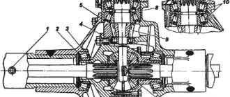
Front axle shank of UAZ Bukhanka
| Position number in the drawing of the UAZ Bukhanka front axle shank | Explanation of position | Catalog number |
| 1 | Drive gear cuff with spring | 374I701210 |
| 2 | oil seal ring | 69-2402037-01 |
| 3 | rear pinion bearing | 3741.2402025 |
| 4 | rear bearing shim | 3741-2402031 |
| 5 | Adjustable spacer 0.15 mm thick rear bearing | 3741-2402032 |
| 6 | rear bearing adjusting shim, 0.25mm thick | 20-2402064-E |
| 7 | rear bearing spacer ring | 3741-2402029 |
| 8 | special nut M20x 1.5 | 292917-P8 |
| 9 | Drive gear washer | 20-2402064-E |
| 10 | Bolt M10x25 | 201497-1129 |
| 11 | Spring washer 10.0 | 252136-P2 |
| 12 | 69-2402100-01 | |
| 13 | Bearing cap | 20-2402051-30 |
| 14 | Bearing cover gasket thickness O.ZO mm | 69-2402035 |
| 15 | bearing cover gasket 0.50 mm thick | 69-2402036 |
| 16 | front pinion bearing | 451D-2402041-01 |
| 17 | front axle drive gear UAZ loaf | 3741-2402017 |
| 18 | driven gear of the front axle UAZ Bukhanka | 3741-2402060 |
| 19 | Cotter pin 4×32 | 258054~P8 |
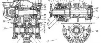
UAZ front axle gearbox
| Position number in the picture of the front axle gearbox of the UAZ loaf | Explanation of position | Catalog number |
| 1 | Front axle differential UAZ loaf with driven gear | 3741-2403010 |
| 2 | adjusting shim, thickness 0.10 mm | 12-2403090 |
| 3 | Adjustment gasket, thickness 0.15 mm | 12-2403091 |
| 4 | adjusting shim, thickness 0.25 mm | 12-2403092 |
| 5 | Adjustment gasket, thickness 0.50 mm | 12-2403093 |
| 6 | Axle shaft (CV joint) gear | 452-2403050-01 |
| 7 | Differential pinion axis | 451D-2403060-02 |
| 8 | Differential satellite | 452-2403055 |
| 9 | Support washer for axle shaft (CV joint) gear | 69-2403031) |
| 10 | Bolt M12×1.25×22 special | 350004 |
| 11 | Spring washer 12.0T | 252137-P2 |
| 12 | UAZ Bukhanka front axle differential assembly | 3741-2403011 |
| 13 | Differential gear box | 3741-2403016 |
| 14 | Left differential gear box cup | 3741-2403019 |
| 15 | Right differential gear box cup | 3741-2403018 |
| 16 | Spring washer 10 | 252136-112 |
| 17 | Bolt M 10×60 | 201509-P |
CV joint and steering knuckle of the front axle UAZ Bukhanka
| Position number in the picture of the front axle UAZ Bukhanka | Explanation of position | Catalog number |
| 1 | Rotary knuckle of the front axle UAZ Bukhanka with brake - right | 31512-2304006 |
| 2 | Steering knuckle of the front axle UAZ Bukhanka with brake, left | 31512-2304007 |
| 3 | Bolt M10x1x16 | 201514-P8 |
| 4 | Spring washer 10.L | 252156-P2 |
| 5 | Bolt M6x12 | 201416-P29 |
| 6 | Spring washer 6.T | 352134-P2 |
| 7 | Steering knuckle oil seal gasket | 69-2304057 |
| 8 | Steering knuckle oil seal spring | 69-2304053 |
| 9 | Steering knuckle oil seal inner race | 452^304051 |
| 10 | Internal sealing ring for steering knuckle oil seal | 69-2304052 |
| 11 | Steering knuckle seal ring | 452-2304054 |
| 12 | Outer sealing ring for steering knuckle oil seal | 69-2304055 |
| 13 | Nut M 10×1 | 250613-P29 |
| 14 | Steering knuckle outer oil seal race | 452-2304056-02 |
| 15 | Special wheel turn stop bolt | 451D-3001040 |
| 16 | Steering knuckle ball joint gasket | 61-121238 |
| 17 | Outer fist | 452-2304062 |
| 18 | Steering knuckle ball | 69-2304069* |
| 19 | Inner right fist | 69-2304064 |
| 20 | Inner left fist | 69-2304065 |
| 21 | Front axle steering knuckle joint UAZ Bukhanka right | 452-2304060 |
| 22 | Left steering knuckle joint | 452-2304061 |
| 23 | Bolt M10x1x30 special | 290784-P29 |
| 24 | Spring washer 10.OT | 252136-L2 |
| 25 | Wheel turn stop | 69-2304078-01 |
| 26 | Oil can | 2.3.45. Ts6 |
| 27 | Front axle steering knuckle lining, upper | 452-2304037-11 |
| 28 | Bolt M12x1.25x25 | 201561-L29 |
| 29 | Spring washer 12.0T | 252137-P2 |
| 30 | Pin 6×11 | 294990-P |
| 31 | Front axle steering knuckle pin | 452-2304019 |
| 32 | Kingpin adjusting shim, thickness 0.1 mm | 469-2304028 |
| 33 | Gasket adjusting kingpin, thickness 0.15 mm | 469-2304029 |
| 34 | Kingpin adjusting shim, thickness 0.4 mm | 469-2304036 |
| 35 | Hinge knuckle seal assembly | 3741-2304071 |
| 36 | Ball support for the steering knuckle of the front axle UAZ Bukhanka assembly | 452-2304012 |
| 37 | Steering pin bushing | 452-2304016 |
| 38 | Thrust washer for the steering knuckle hinge of the front axle UAZ Bukhanka | 3741-2304024 |
| 39 | Washer support king pin | 452-2304023 |
| 40 | Right steering knuckle housing | 452-2304040-12 |
| 41 | Left steering knuckle housing | 452-2304041-12 |
| 42 | Bottom steering knuckle pad | 452-2304038-11 |
| 43 | Left front axle steering knuckle | 69-2304011-11 |
| 44 | Right steering knuckle of the UAZ Bukhanka front axle | 69-2304010-11 |
| 45 | Steering arm stud | 469-2304102 |
| 46 | Steering knuckle lever stud expansion bushing | 469-2304101 |
| 47 | Nut Ml2x1.25 | 250515-P29 |
| 48 | Steering knuckle lever | 69-2304100-10 |
| 49 | Hub drive flange coupling | 452-2304114-10 |
| 50 | Ball B4-200 | 263003 |
| 51 | Locking spring for the sliding clutch of the front axle flange of the UAZ Bukhanka | 11-405662 |
| 52 | Drive Flange Coupling Bushing | 452-2304116-B |
| 53 | Drive flange coupling bolt | 3741-2304U8 |
| 54 | Hub drive flange coupling assembly | 452-2304112-01 |
| 55 | Front wheel hub cap | 452-3103065 |
| 56 | BoltM10×28 | 350007 |
| 57 | Lock washer for front wheel bearing nuts | 69-2401055 |
| 58 | Wheel bearing nut and locknut | 69-2401052 |
| 59 | Hub drive flange gasket | 3151-2407048 |
| 60 | Hub drive flange | 452-2304091 |
| 61 | Steering knuckle axle assembly | 69-2304080 |
| 62 | Steering knuckle gasket | 69-2304084 |
| 63 | Lock washer for hub bearing nuts | 61-121168 |
| 64 | Bolt Ml0x28 | 290776-P8 |
| 65 | Steering knuckle axle bushing | 69-2304083 |
| 66 | Steering knuckle axle bushing | 69-2304081 |
| 67 | Stugszcz cuff ring | 69-2401025 |
| 68 | Front wheel release clutch | 31512-2304210« |
Front axle hub UAZ Bukhanka
| Position number in the picture of the front axle hub of the UAZ loaf | Explanation of position | Catalog number |
| 1 | Wheel 6L-15 | 450-3101015-01 |
| 2 | Hub and brake drum assembly | 69-3103010-13 |
| 3 | Wheel hub bolt nut | 20-3101040-B |
| 4 | Lock washer | 69-2401055 |
| 5 | Hub bearing nut | 69-2401052 |
| 6 | Wheel hub | 69-3103015-01 |
| 7 | Lock washer | 61-21168 |
| 8 | Bearing | 3151-3103025 |
| 9 | Bearing thrust ring | 69-3103024 |
| 10 | Hub seal thrust washer | 469-3103032 |
| 11 | Hub cuff with spring assembly | 3741-310303* |
| 12 | Oil deflector gasket | 469-3103055 |
| 13 | Oil deflector | 452-3103060 |
| 14 | Volt speed wheels | 20-3l03008-? |
| — | Wheel hub and brake drum (spare parts kit*) | BK-69-3103006-H |
Features of using blocking on UAZ
A differential lock is a special mechanism by which the unit is locked so that it cannot perform its main function. In this case, all the wheels of the car begin to work equally. The presence of such a mechanism is good for those cars that often go off-road: that’s where it will be needed. Differential locking is most needed on the UAZ, which is considered a real all-terrain vehicle.
The presence of such a mechanism increases the vehicle’s maneuverability on difficult sections of the road. This increases the load on some parts of the transmission. Locking the front differential can affect your vehicle's cornering ability. Do not use this mechanism too often; it should only be used on particularly difficult sections of the road.
Currently, there are several types of locks.
- Self-locking differential of a rigid type, which should automatically operate in the event of a difference in wheel speed. When using it, you can expect deterioration in the car's performance when cornering.
- The hydraulic cylinder is controlled by a special lever located inside the car.
- An electric drive that operates via a compressor and is controlled by a button on the remote control.
- The pneumatic drive operates similarly to the previous version.
Appearance of the mechanism
In a UAZ that has a self-locking differential, the device will be blocked if the suspension wheel is twisted a few degrees. The differential can remain in this state for quite a long time, while all remaining parts are not subject to wear.
Installing a lock on a UAZ Patriot can be done in several ways:
- increased friction for limited slip
- installation of a self-locking differential on a UAZ
- the use of cabinets that ensure maximum rigidity of the mechanism.
Checking and adjusting the axial clearance of the Timken UAZ Bukhanka bridge pins
In this section, we will look at checking and adjusting the old-style UAZ Bukhanka front axle pins. Adjusting and checking the axial clearance of the pins is performed in the following sequence.
- It is necessary to install stops under the front and rear wheels;
- Jack up the front axle from the adjustable knuckle side;
- Unscrew the wheel nuts and remove the front wheel;
- Unscrew the ball joint oil seal bolts and move the oil seal to the side;
- We check the play in the king pins. To do this, holding the top and bottom of the brake drum with your hands, rock it in a vertical plane;
- To eliminate play in the kingpins, unscrew the nuts of the studs securing the steering knuckle lever 9 or the bolts of the lining 15 and remove the lever or lining;
- Remove the adjusting shim with a thickness of 0.1 mm;
- We install the upper trim 15 or the steering knuckle lever 9 in place;
- Unscrew the bolts of the lower lining 30 of the steering knuckle and remove it;
- We take out the lower adjusting shim with a thickness of 0.1 mm. To maintain the alignment of the steering knuckle joint, it is necessary to remove shims of the same thickness from above and below;
- We mount the lower pad 30 of the steering knuckle in place;
- We check the play in the steering knuckle pins of the front axle of the UAZ Bukhanka as described in point 5;
- If there is still play, then instead of a 0.1 mm thick gasket, remove a 0.15 mm thick gasket;
- If one 0.15 mm spacer is not enough to eliminate play in the pivots, then remove two 0.1 mm spacers. In this way we achieve the elimination of gaps in the king pins.
- After eliminating the gaps in the kingpins, we mount the ball joint oil seal in place;
- We mount the front wheel in place;
- Using the same method, we eliminate the play in the kingpins of the second steering knuckle;
- Remove the wheel chocks from under the wheels.
Excessive wear of the pins 14 and bushings 29 in diameter causes a violation of the camber angle of the wheels, their “wobbling” when driving and uneven wear of the tires. If this is observed on your UAZ car, then replace bushings 29 and king pins 14.
Gearbox device
The UAZ 469 gearbox for the wheels of the front drive axle is absolutely identical in design to the wheel gearbox of the rear axle. The only difference from it is the installation and fastening of the drive gear, as well as the design of the ball bearing 10, which is mounted in a special cup. The rear axle of the UAZ 469 collective farm axle has a slightly different gearbox design.
The drive gear is located on the involute splines of the driven hinge fork. It is secured together with the bearings with a special nut 19, which, after tightening, is drilled into the groove of the UAZ-469 front axle shaft. A support washer 20 is installed in the gap between the gear and the roller bearing.
The drive gear and ball bearing of the front drive axle gearboxes are not interchangeable with similar parts of the rear gearboxes. In all other respects, the front gearboxes are designed identically to the rear gearboxes and require the same maintenance and repair.
Front axle UAZ 469 military (Front axle with final drive)
General view of the front military axle UAZ 469
| Position number in the picture of the front axle UAZ 469 | Explanation of position | Catalog number |
| 1 | UAZ 469 front axle with brakes and hubs (military) | 3151-2300010 |
| 2 | front axle with brakes and hubs | 3151-230001G |
| 3 | UAZ 469 front axle with brakes and hubs (military) | 3151-2300011-03+ |
| 4 | safety valve | 308387-P |
| 5 | Cork KG 1/2″ | Ar24457-A |
| 6 | Front axle housing with axle housing and differential bearing outer ring assembly | 469-2301010-30 |
| 7 | Gasket for the crankcase cover of the front axle UAZ 469 | 469-2401040 |
| 8 | 452-2403036 | Bearing |
| 9 | Front axle without steering knuckles | 469-2300015-02 |
| 10 | Front axle crankcase cover UAZ 469 with axle housing and differential bearing outer ring assembly | 469-2301013-30 |
| 11 | Bolt M 10×28 | 350007 |
| 12 | Spring washer 10.OT | 252136-P2 |
Design of the front military axle UAZ 469
| Position number in the picture of the front axle UAZ 469 | Explanation of position |
| 1 | Steering linkage rod |
| 2 | Bipod steering rod |
| 3 | Final drive |
| 4 | Steering knuckle lever |
| 5 | Steering knuckle housing |
| 6 | screw |
| 7 | Flange |
| 8 | Cuff |
| 9 | Ring |
| 10 | Drive gear bearing small |
| 11 | Spacer |
| 12 | Drive gear bearing large |
| 13 | Adjustment ring |
| 14 | Main drive driven gear |
| 15 | Breather |
| 16 | Final drive drive gear |
| 17 | Final drive driven gear |
| 18 | Driven gear bolt |
| 19 | Final drive driven shaft |
| 20 | Trunnion |
| 21 | Brake drum |
| 22 | Leading flange |
| 23 | Special nut |
| 24 | Drive shaft bearing |
| 25 | Final drive housing cover |
| 26 | Axle bearing |
| 27 | Half shaft |
| 28 | Sealing gasket |
| 29 | Final drive housing |
| 30 | Final drive housing cover |
| 31 | Final drive housing |
| 32 | Drive gear of the main gear of the front axle UAZ 469 |
| 33 | Shims |
| 34 | Mud deflector |
| 35 | Wheel release clutch |
| I | Front axle UAZ 469 |
| II | Rear axle |
UAZ front military axle shank
| Position number in the picture of the UAZ front military axle | Explanation of position | Catalog number |
| 1 | cuff with spring | 3160-2402052 |
| 2 | drive gear collar | 3160-2402054 |
| 3 | Drive gear cuff spring | 3160-1701220 |
| 4 | Gear adjusting ring 1.38 mm thick | 469-2402046 |
| 5 | Drive gear adjusting ring 1.43 m thick | 469-2402047 |
| 6 | Drive gear adjusting ring 1.48 mm thick | 460-2402048 |
| 7 | Drive gear adjusting ring 1.53 mm thick | 460-2402049 |
| 8 | Drive gear adjusting ring 1.58 mm thick | 460-2402050 |
| 9 | Drive gear adjusting ring 1.63 mm thick | 469-2402073 |
| 10 | Drive gear adjusting ring 1.68 mm thick | 469-2402075 |
| 11 | Drive gear adjusting ring 1.73 mm thick | 469-2402076 |
| 12 | Drive gear adjusting ring 1.78 mm thick | 469-2402077 |
| 13 | Drive gear adjusting ring 1.83 mm thick | 469-2402078 |
| 14 | Drive gear adjusting ring 1.88 mm thick | 469-2402079 |
| 15 | Driven gear of the main drive of the front axle UAZ 469 | 469-2402060 |
| 16 | Drive gear for the main drive of the front axle UAZ 469 | 469-240201? |
| 17 | Main gear drive bearing | 469-2402041 |
| 18 | Drive gear flange | 69-1802044-01 |
| 19 | Reflector | 451D-2402040 |
| 20 | Flange for fastening the propeller shaft to the main gear drive gear with reflector assembly | 469-2402100-01 |
| 21 | Washer of the flange securing the propeller shaft to the drive gear | 20-2402064-B |
| 22 | Nut M20x1.5 | 292917-P29 |
| 23 | Cotter pin 4×32 | 258054-P29 |
| 24 | Main gear drive bearing | 469-2402025-10 |
| 25 | Adjusting gasket for drive gear bearings, 0.25 mm thick | 3151-2402033 |
| 26 | Drive gear bearing spacer sleeve | 469-2402029-10 |
| 27 | Drive gear bearing adjusting washer 2.20 mm thick | 469-2402035 |
| 28 | Drive gear bearing adjusting washer 2.15 mm thick | 469-2402034 |
| 29 | Adjusting washer for drive gear bearings 2 1 Ohm thick | 469-2402033 |
| 30 | Adjusting washer for drive gear bearings, 2.05 mm thick | 469-2402032 |
| 31 | Drive gear bearing adjusting washer 2.0 mm thick | 469-2402031 |
| 32 | Drive gear bearing thrust washer | 469-2402038 |
| — | Gears driving and driven main gear | UK-469-2402020 |
Differential of the front military axle UAZ 469
| Position number in the picture of the front military axle UAZ 469 | Explanation of position | Catalog number |
| 1 | Front axle differential with driven gear | 469-2403010-01 |
| 2 | adjusting shim 0.10 mm thick | 12-2403090 |
| 3 | Regulating gasket 0.15 mm thick | 12-2403091 |
| 4 | adjusting gasket 0.25 mm thick | 12-2403092 |
| 5 | adjusting shim 0.50 mm thick | 12-2403093 |
| 6 | Front axle axle gear of UAZ 469 | 469-2403050 |
| 7 | Differential pinion axis | 469-2403060-01 |
| 8 | Differential satellite | 469-2403055 |
| 9 | Axle gear support washer | 469-2403030 |
| 10 | Washer YL | 252156-P2 |
| 11 | BoltM10x1x21 | 350204-P |
| 12 | Front axle differential UAZ 469 | 469-2403011-01 |
| 13 | Differential box | 469-2403016-11 |
| 14 | Left differential cup | 469-2403019-12 |
| 15 | Differential cup right | 469-2403018-10 |
| 16 | Spring washer Y.OT | 252136-P2 |
| 17 | Bolt Ml0x60 | 201509-P |
Knuckle of the front military axle UAZ 469
| Position number in the picture of the front military axle UAZ 469 | Explanation of position | Catalog number |
| 1 | Right steering knuckle of the front axle UAZ 469 with brake | 3151-2304006 |
| 2 | Left steering knuckle of the front axle UAZ 469 with brake | 3151-2304007 |
| 3 | Spring washer 6T | 252134,P2 |
| 4 | Bolt M6x12 | 201416-P29 |
| 5 | YUL spring washer | 252156-P2 |
| 6 | BoltM10x1x16 | 201514-P8 |
| 7 | Ball joint gasket | 469-2304026 |
| 8 | Wheel turn stop bolt | 451D-3001040 |
| 9 | MIOxl nut | 250613-P29 |
| 10 | Outer seal ring | 452-2304056-02 |
| 11 | Outer sealing ring for steering knuckle oil seal | 69-2304055 |
| 12 | Ring-septum | 452-2304054 |
| 13 | Internal sealing ring | 69-2304052 |
| 14 | Oil seal inner race | 452-2304051 |
| 15 | Steering knuckle oil seal spring | 69-2304053 |
| 16 | Steering knuckle oil seal gasket | 69-2304057 |
| 17 | Right steering knuckle joint with bearings | 469-2304058-01 |
| 18 | Left steering knuckle joint with bearings | 469-2304059-01 |
| 19 | Outer knuckle joint | 469-2304062 |
| 20 | Central steering knuckle ball | 69-2304069 |
| 21 | Inner right steering knuckle knuckle | 469-2304064 |
| 22 | Steering knuckle joint inner left knuckle | 469-2304065 |
| 23 | Steering knuckle ball | 508626-A*1 |
| 24 | Right steering knuckle joint | 469-2504060 |
| 25 | Left steering knuckle joint | 469-2.W4061 |
| 26 | Bolt Ml Ox 1×30 | 290784-P29 |
| 27 | Spring washer Y.OT | 252136-P 2 |
| 28 | Wheel turn stop | 469-2304078 |
| 29 | Ball joint for steering knuckle | 469-2304012-Q] |
| 30 | Steering pin bushing | 452-2304016 |
| 31 | Steering knuckle thrust washer | 3741-2304024 |
| 32 | Ball joint for steering knuckle - processing | 469-2304015 |
| 33 | Ball joint seal | 3741-2304071 |
| 34 | Ball joint seal spring | 67-1*1083 |
| 35 | Gasket adjusting pin 0.10 mm thick | 469-2304028 |
| 36 | Gasket adjusting pin 0.15 mm thick | 469-2304029 |
| 37 | Gasket adjusting pin 0.40 mm thick | 469-2304036 |
| 38 | Bottom steering knuckle pin cover | 452-2304038-11 |
| 39 | Spring washer 12.0T | 252137-P2 |
| 40 | Bolt Ml 2×1.25×25 | 201561-P29 |
| 41 | Nut M12x1.25 | 250515-P29 |
| 42 | Grease fitting | 2.3.45.Ц6 |
| 43 | Steering knuckle lever stud expansion bushing | 469-2304101 |
| 44 | Steering knuckle lever | 469-2304100-01 |
| 45 | Lever pin | 469-2304102 |
| 46 | Pin 0 6×11 locking | 294990-P |
| 47 | King pin | 452-2304019 |
| 48 | Washer support king pin | 452-2304023 |
| 49 | Right steering knuckle housing assembly | 469-2304040-13 |
| 50 | Left steering knuckle housing assembly | 469-2304041-13 |
| 51 | Reducer drive gear outer bearing housing | 469-2407040-01 |
| 52 | Right steering knuckle housing | 469-2304042-11 |
| 53 | Front axle steering knuckle housing UAZ 469 left | 469-2304043-11 |
| 54 | Bolt MIOxl | 350204-P |
| 55 | Upper steering knuckle pin cover | 452-2304037-11 |
* — As part of the front axle 3151-2300010
*1 — Balls of the following letter series: 508626-A, 508626-B, 508626-B, 508626-G, 508626-D, 508626-E, 508626-Zh, 508626-I, 508626-K
*2 - As needed
Reducer of the front military axle UAZ 469
| Position number in the picture of the front military axle UAZ 469 | Explanation of position | Catalog number |
| 1 | Wheel reducer shaft with driven gear assembly, right | 469-2307120-01 |
| 2 | Wheel reducer shaft with driven gear assembly, left | 469-2307121-01 |
| 3 | Driven gear shaft of the wheel reducer, right | 469-2307122-01 |
| 4 | Wheel reducer driven gear shaft, left | 469-3307123-01 |
| 5 | Driven gear of wheel reducer | 469-2407134 |
| 6 | YUL spring washer | 252156-Ш |
| 7 | Bolt M10x1x21 | 350ED4-P |
| 8 | Cork KG 1/2″ | A-24457-A |
| 9 | Drive gear bearing internal | 469-2307086-02 |
| 10 | Drive gear bearing cup | 469-2307095 |
| 11 | Drive gear of the wheel reducer of the front axle UAZ 469 | 469-2307090-01 |
| 12 | Support washer for the drive gear of the wheel reducer | 469-2307093 |
| 13 | 451D-2402041-01 | Outer drive gear bearing |
| 14 | Drive gear bearing lock nut | 469-2307088 |
| 15 | Front wheel hub drive flange | 3151-2307091 |
| 16 | Hub drive flange gasket | 3151-2407048 |
| 17 | Bolt Ml0x25 | 201497-P29 |
| 18 | Spring washer 10.OT | 252136-P2 |
| 19 | Gearbox cover gasket | 469-2407111 |
| 20 | Driven gear shaft bearing of wheel reducer | 469-2407126 |
| 21 | Front axle gearbox cover | 469-2407104 |
| 22 | Driven gear shaft bearing mounting nut, right | 469-2407138 |
| 23 | Left driven gear shaft bearing mounting nut | 469-2407139 |
| 24 | Wheel reduction axle gasket | 69-2304084 |
| 25 | Driven gear shaft bearing spring gasket | 469-2407127 |
| 26 | Wheel reducer axle assembly | 469-2407160 |
| 27 | Wheel reducer axle bushing | 69-2304083 |
| 28 | Wheel reducer axle | 469-2407162 |
| 29 | Hub oil seal bushing | 469-2407165 |
| 30 | Sliding coupling for hub drive flange | 452-2304114-10 |
| 31 | Sliding clutch retaining spring | 11-405662 |
| 32 | Ball | 263003 |
| 33 | Hub Drive Flange Sliding Clutch Bolt | 3741.2304Ц8 |
| 34 | Hub Drive Flange Sliding Clutch Bushing | 452-2304116-B |
| 35 | Bolt Ml 0x28 | 350007 |
| 36 | Sliding coupling for hub drive flange assembly | 452-3304112-01 |
| 37 | Front wheel hub cap | 452-3103065 |
| 38 | Wheel release clutch | 31512-2304210*’ |
| 39 | Hairpin M10x1xZO | 351О0О-Ш |
| 40 | Nut M10xl | 292779-L8 |
* — As part of the front axle 3151 -5300010
*1 Installed in the axle configuration 3151 -2300011 -03 instead of 3151 -2307091, 4S2-2304 AND 2-01,452-3103065
Maintenance
Maintenance of the rear axle consists of maintaining the oil level in the crankcase and replacing it in a timely manner, checking the seals, and timely detecting and eliminating axial clearances in the final drive gears. Periodically clean the safety valve and tighten all fasteners.
If the oil in the crankcase is heavily contaminated or there are metal particles in it, wash the crankcase with kerosene before adding fresh oil. To flush, pour 1–1.5 liters of kerosene into the crankcase; raise the wheels, start the engine and let it run for 1.0–1.5 minutes, then drain the kerosene and fill with fresh oil.
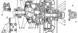
Rice. 3.79. Rear axle: 1 – safety valve; 2 – differential bearing; 3.8 – adjusting shims; 4 – rear bearing of the drive gear; 5* – adjusting ring; 6 – oil removal ring; 7 – nut; 9 – drive gear; 10 – front bearing of the drive gear; 11 – thrust washer of the semi-axial gear; 12 – driven gear. (* Not installed since 1991)
Axial play of the drive gear of the fixed gear is not allowed. Check the clearance by rocking the drive gear by the driveshaft mounting flange. If an axial play of the drive gear of more than 0.05 mm appears during vehicle operation, tighten nut 7 (Fig. 3.79). Tightening torque – 167–206 N m (17–21 kgf m). If the gap does not disappear, make adjustments as indicated in the chapter “Assembling and adjusting rear axle components.”
Axial play of the main drive driven gear is not allowed. Check it by moving the gear through the oil filler hole. To eliminate the gap, add sets of shims of equal thickness between the ends of the differential and bearings.
Do not add shim sets of different thicknesses or install them on the same side of the driven gear because this will lead to disruption of the engagement of worn-in gears and their rapid breakdown.
Advantages and disadvantages
Automation has a number of advantages:
- The lock is activated in any difficult situation, and the driver does not need to be distracted to activate it.
- An automatic system is much easier to install than a manual lock.
However, there are also disadvantages to consider:
- The constant locking effect makes itself felt: the steering wheel twitches slightly and the wheels make noise when turning.
- The moment the gears are automatically engaged is clearly felt by a click, which irritates many.
Types of locks
A differential lock is primarily used to transfer engine torque to the wheel that has the best traction. Based on this, differentials are divided into center and center differentials, which differ in the way they are locked. Any of these options can be installed as a UAZ Patriot differential.
Previously, only forced locks, which appeared on the automotive market just a few years ago, were used for such purposes. Produced under the Sprut brand, this blockade operated by analogy with the well-known EPIRB. Today there are several other types of locks, which differ greatly in their operating principle.
The screw retainer is already used on UAZ and differs from its predecessors in its relatively long service life. The service life of the mechanism is almost the same as that of the integrated transmission, and at the same time it has good cross-country characteristics. This type works especially well on slippery surfaces. But there is one problem: as soon as the car loses control of at least one wheel, the system begins to fail and its performance immediately drops.
Lock testing
The Krasikov type automatic differential looks very similar to its own, this type of locking proved to be the best in all tests, regardless of the type of task being performed. During testing, this type of blocking turned out to be the best, no matter what tasks were offered. It is not yet known how long the mechanism will work properly and without failures.
The operation of the cam lock depends on the steering cams. When at least one wheel of the car slips, the cams engage with the gears. This system has proven itself on slippery roads. It will last quite a long time regardless of operating conditions.
The operation of a cam lock depends entirely on the rotating cams. If at least one of the car's wheels slips, the cams engage with the gears. This system has proven itself on slippery roads. It will last quite a long time regardless of operating conditions.
Advantages and disadvantages
First of all, you should pay attention to the advantages of manual differential locking:
- When the system is switched off, the differential operates as standard and you can get the most out of it.
- The driver decides when to lock the system, so the limiter is not used in vain.
However, the disadvantages are the following:
- You have to look away from the controls for a while to press a switch, and you often have to do this under the most challenging conditions.
- The lock must be turned off in time, otherwise the differential itself can be damaged.
- It is necessary not only to install the limiter itself, but also to mount the mechanism that will activate it and the button on the instrument panel.
Advantages and disadvantages of locking systems
The hard version of the lock will be gradual. Destroy the car's gearbox. When driving on this element, the car constantly affects the so-called Variable Force Sign. This results in engine torque being transmitted to only one wheel, causing shaft interruption.
Using a positive lock has one advantage: the driver turns it by hand. As a rule, the cost of this option is quite significant, but there are no other visible defects. A differential mechanism with increasing types of friction or self-locking allows torque to be transmitted to both wheels at the right time, and the car can continue to drive.
The downside to this option is that the mechanism installed tends to cause both wheels to spin at the same speed even when going around corners. As a result, despite attempts to turn the steering wheel in any way, the car automatically goes straight. The cost of this differential mechanism is relatively low, and its installation does not take much time. The driver is then required to take special care when performing any maneuvers on the road.
You can buy a differential locking mechanism at any automotive market or specialty store. You can use the manufacturer's services and purchase the product. The most important thing is to know what type of device is suitable for this car. For UAZ, it is best to use the Military Axis and Spicer connection locking mechanism.
You can buy a differential lock mechanism at any automobile market or in a specialized store. You can use the manufacturer's services and purchase the product. The most important thing is to know what type of device is suitable for this car. For UAZ, it is best to use the interaxle difference between the “military axle” and the “Spicer”.