The electric starting system is designed to crank the engine at the frequency required for starting.
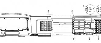
The main elements of the electric start system for a KamAZ vehicle are (Figure 16.1):
— starter ST142B2 M1;
— two rechargeable batteries 6ST-190AP (G2, G3);
— instrument and starter switch VK353 (or VK354) S21;
— starter blocking relay 3302.3777 (V2);
— external start socket PS315 X35;
When the instrument switch and starter key VK353 (Figure 16.1) is moved to position I, terminal 2 of the starter interlock relay is supplied with power from the battery. In this case, the trigger assumes its initial state in which the PC530 starter activation relay is connected to the car body. When starting the engine, the instrument and starter switch key is set to position II.
The PC530 starter activation relay is activated. The current through the relay winding flows along the following path: “+” of the battery, contacts VK353, terminal K, winding of the starter activation relay, terminal 3 of the starter blocking relay, open transistor of the relay trigger (Figure 4.28), terminal 1, “ground”, “-” battery.
The contacts of the starter activation relay close and connect the starter traction relay to the battery. At the same time, the traction relay, through a double-arm lever, engages the starter gear with the flywheel ring gear. The current from the “+” battery flows through the traction relay bolts closed by a contact disk to the starter motor, housing and “-” batteries. When the engine crankshaft rotates, pulses of positive polarity (from the tachometer sensor or generator) are supplied to input 4 of the starter blocking relay, and the rotation speed of the flywheel exceeds the speed of the drive gear. The ratchet clutch slips.
Figure 16.1 — KamAZ electric starting system
At a certain crankshaft rotation speed, the locking relay interrupts the power supply circuit of the starter relay winding and the starter turns off. To turn on the starter again, you must move the instrument and starter switch first to position O (“off”), and then sequentially to positions I and II.
The backup switch VK317A2 is used to start the engine when performing adjustment work in the engine compartment of a car.
Connecting the KAMAZ starter blocking relay
Kamaz repair
How to connect a 4- and 5-pin relay. Why?
Kamaz 2 repair
Starter Interlock Relay
Installing an additional starter relay on a VAZ 2112
Installation of Pantera CL 500 alarm system on VAZ 2104, 2105, 2107 (part 3)
VEHICLE ELECTRICAL EQUIPMENT.
emergency starter start. on DAF 105
Starter relay
We connect the wires to the ignition switch of the VAZ “classic” 01 - 07.
Also see:
- Accident KAMAZ with a trailer
- Fuel injection timing of a KAMAZ diesel engine
- Accidents with KAMAZ
- Repair of KAMAZ wheel rim
- KAMAZ flatbed 3 bridge
- KAMAZ 45143 for leasing
- Thermostat KAMAZ 55102
- KAMAZ cylinder block in section
- Maintenance of timing belt KAMAZ 5320
- KAMAZ presented a new cab
- KAMAZ 6460 tractor weight
- Fuel separator for KAMAZ diesel engines
- Repair of the front drive axle of KAMAZ
- KAMAZ with a trailer in the mafia
- Headlight KAMAZ euro adjustment
Home » New » Connecting the KAMAZ starter lock relay
kamaz136.ru
Products: 8602.3777
- about the company
- products
- contacts
61,45 ₽
≈ 0.95 $ or 0.85 €
73,74 ₽
≈ 1.14 $ or 1.02 €
small box 40 pcs small high box 50 pcs medium box 100 pcs applicability KAMAZ, KRAZ, URAL, ZIL Analog RBS 2602.3747 code OKP45 7374 9095 catalog number voltage 24 V weight 49 connector 64321 barcode short link emi-penza.ru/p/8602.3777 copy
You may also be interested in ⟳
- ←583.377712 V, analogue of RS 431
- →8602.3777-0124 V, analogue of RSE 8522.3777
- 30.3847analogue 191.3847
- 642.3777-0112 B, analogue 642.3747-01
- 77.3702-0228 V, 5 A, analogue Y120M1I2
- 8612.3777-0112 B, analogue 7302.3777-01
- 981.3777-00124 V, 40 A, analogue 901.3747-RK
- 64.3855-03analogue 21083-3839210-03
- 773.370214 V, analogue Ya112V, Ya112V1, 411.3702, 4322.3722
- 68.378712 V, analogue of ERP 1
How to buy our products
It's easy to start collaborating with EMI - just contact us by phone or send an email. The order execution time is 1–3 business days after payment by bank transfer. We deliver the products to the transport company or load them into the client’s car upon pickup.
Starter blocking relay for KAMAZ
Kamaz repair
How to connect a 4- and 5-pin relay. Why?
Starter Interlock Relay
Kamaz 2 repair
Installing an additional starter relay on a VAZ 2112
VEHICLE ELECTRICAL EQUIPMENT.
Starting modified engine PDM for T 150, DT 75 with a starter from KAMAZ
Starter relay
Installation of Pantera CL 500 alarm system on VAZ 2104, 2105, 2107 (part 3)
starter causes of malfunction part 1
Also see:
- Rabbit and KAMAZ
- Corrugation of the KAMAZ intake pipe
- KAMAZ car fender
- Vacuum vehicles based on KAMAZ
- Where is the KAMAZ frame number 55102
- Compressor brand at KAMAZ
- Cabin air cushions for KAMAZ 4308
- Agreement with KAMAZ driver
- KAMAZ manual brake valve repair
- New KAMAZ 2014 truck
- KAMAZ 53215 technical specifications video
- Weight of KAMAZ with manipulator
- Spare parts for KAMAZ 53213
- Filming a KAMAZ engine video
- KAMAZ with Deutz engine
Home » Clips » Starter blocking relay for KAMAZ kamaz136.ru
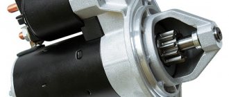
General information about the starting system
- It is located on the flywheel housing on the driver's side.
- Fastens with 3 bolts and a stud.
- The series starter electric motor operates on direct current
.
In addition to the body itself, it contains the following components:
- anchor,
- excitation winding,
- brush and commutator,
- drive shaft,
- two covers (front and back).
The device body acts as a magnetic circuit with cores attached to it. The front starter cover directly covers the drive mechanism, while the rear cover covers the assembly with brushes and commutators. A rectangular copper wire is used in the excitation winding
.
One end of it goes to the insulated terminal of the housing, the other to the positive brushes. The winding turns are insulated using impregnated cable paper.
Starter blocking relay for KAMAZ
Kamaz 2 repair
How to check, connect the signal, ignition, starter relay......
Starter Interlock Relay
ANSWER. Diagram of additional starter relay.
KAMAZ 65115
How to connect a 4- and 5-pin relay. Why?
The starter does not work. What is the reason?
There is a starter relay, but the starter still does not turn on from the ignition switch.
Starter connection diagram
VEHICLE ELECTRICAL EQUIPMENT.
Also see:
- Front wheel hub KAMAZ 4308
- KAMAZ 65115 2008 characteristics
- Main malfunctions of the steering control of KAMAZ 4310
- KAMAZ 4308 extended
- Tour of the KAMAZ plant
- KAMAZ 54115 1993
- Radiator KAMAZ 6520 manufacturer
- Tightening the KAMAZ front hub nut
- How to change the balancer axle on a KAMAZ
- Crosspiece KAMAZ 65115 size
- Tracks on the rear wheels of KAMAZ
- Brakes on KAMAZ do not work well
- Headlights for KAMAZ without lenses
- How to properly tighten the KAMAZ cylinder head
- KAMAZ site for lease
Home » Clips » Starter blocking relay for KAMAZ
kamaz-parts.ru
Failure options
There are no spare parts that last forever, so it is important to “catch” in time the moment of breakdown of an important starting unit that slows down the operation of the entire truck. Why does the relay break?
- Internal burnout of the nickel plates occurs.
- Often the fragile winding burns out.
- Metal fatigue, subsequent destruction of metal components.
The primary symptom of a breakdown is the lack of engine response to turning the ignition key. When several attempts end in nothing, you should prepare for repairs. The starter itself is designed quite simply; with instructions, even an amateur can disassemble it and fix the problem. The most important thing is to dismantle it correctly and then connect all the components correctly. Initially, the location of the breakdown is determined. The search most often begins at the ignition switch - the initial boundary of the electric current. The surest symptom is the absence of engine starting sounds when you turn the key. Clicks, noise of a rotating shaft, you can try to close the bolts on the back with a metal object, applying voltage directly to the windings. Any damage is clearly visible only after disassembly. You can only check the winding remotely using an ohmmeter. The resistance of the housings at the ends must reach at least 10 kilo Ohms; a lower value means a malfunction of the windings.
KAMAZ ELECTRICAL SCHEMES | AUTOMOTIVE ELECTRICAL DIAGRAMS
Continuation. See the beginning here.
Find out how to save circuit drawings on your computer here.
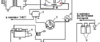
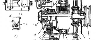
- Fig.1. Electrical circuit diagram of systems that provide engine starting: 1 - heater relay; 2 — switch for operating modes of the engine liquid heater; 3 — button for turning on candles; 4 — torch candles; 5. 29 — electromagnetic valves; 6 - ECU relay; 7 — EFU thermal relay; 8 — electric torch device; 9 - ammeter; 10 — starter relay; 11 - generator; 12 — relay for disconnecting the generator excitation winding; 13 — starter blocking relay; 14 — tachometer; 15 - voltage regulator; 16 — starter; 17, 20. 32 - fuses; 18 — electric start system; 19 — battery switch; 21 — instrument and starter switch; 22 — batteries; 23 — external start socket; 24 — remote control button to turn off the batteries; 25 — ignition coil of the Russian Railways with a switch; 26 — spark plug; 27— pre-heater; 28 — fuel heater; 30 - electric motor; 31 - contactor; 33 - backup starter switch
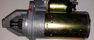
- Fig.2. Starter ST142B: 1 - sealing rings; 2 — intermediate bearing holder; 3 - bandage; 4 — anchor; 5 — body; 6, 27 — covers; 7 - collector; 8 — bolt for fastening the brush holder traverse; 9, 28 — bearing; 10 - felt; 11 — brush holder traverse; 12 — brushes; 13 — excitation winding; 14 - connecting bus; 15 — main clamp; 16 — clamp of relay windings; 17 — contact disk; 18, 19 - pulling and holding windings; 20 — return spring; 21 — anchor; 22 — rubber casing; 23 — drive lever; 24 — eccentric axis; 25 - drive; 26 - gear; 29 - thrust washer.
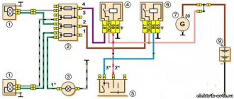
- Fig.3,4,5. Electrical (a) and wiring (b) diagrams of the starter interlock relay download with description.
- Rice. 6. Electrical circuit diagram of the PZD30 pre-heater: GBl, GB2 - batteries; S1 - battery switch; S2 — heater operating mode switch; K1 - contactor for turning on the electric motor; K2 - relay for turning off the electric fuel heater; R.heater—electric fuel heater; Y1, Y2 - electromagnets; F spark plug; T1 - ignition coil; M - electric motor; V1—V3—diodes.
Fig.1. Electrical schematic diagram of systems that ensure starting the KAMAZ engine
Starter Kamaz ST142B
Fig.6. Electrical circuit diagram of the PZD30 pre-heater on KamAZ
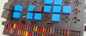
Fuse F5
Fuse F5 is installed on the front panel of the cab.
Fuse F5 1 - To fuse block F4; 2 - fuse F5; 3 - jumper; 4 — “Generator-fuse” wire; 5 — wire “Battery - fuse”; 6 - fuse wire; 7 - to fuse block F1; 8 - fuse wire
Bibliographic link to the article:
// Modern equipment and technologies. 2012. No. 5 [Electronic resource]. URL: https://technology.snauka.ru/2012/05/946 (access date: 02/07/2019).
Ph.D. tech. Sciences Gumelev V.Yu.,
Ph.D. tech. Sciences Kartukov A.G.,
The starter blocking relay 2612.3747 is used to automatically turn off and block the starter when the engine is running. It is installed on engines of vehicles of the KamAZ and URAL families [1, 2].
The appearance and installation of the relay in the cabin of the URAL-4320-31 car are shown in Figures 1 and 2. The relay is installed to the left of the steering column under the instrument panel.
a – appearance of the relay; b – arrangement of elements on the circuit board
Figure 1 – Starter interlock relay 2612.3747
a – relay mounting; b – placement and connection of the relay using a plug connector
Figure 2 – Installation of starter interlock relay 2612.3747
in the cabin of the URAL-4320-31 car
The relay is activated at an engine crankshaft speed of (500-600) min -1 at a temperature of plus 20 0 C, opening the power circuit of the winding (coil) of the starter traction relay. As the temperature increases, the relay operates at lower speeds and vice versa.
By automating the shutdown of the starter after starting the engine, the reliability of the electric starting system and the service life of the starter are significantly increased. Information about the shaft speed is supplied to the blocking relay from one of the phases of the generator 1702.3771 – terminal “W” (G 288E – terminal “L1”).
The technical characteristics of the starter blocking relay 2612.3747 are presented in the table.
Table - Main characteristics of the starter interlock relay 2612.3747
| Characteristic | Unit |
| Rated supply voltage | 24 |
| Variable supply voltage | |
| Current consumption in mode: |
starter blocking/operation
no more than 80 / 300
Automatic starter shutdown
at UВХ not less than 2.5 V
The connection of the starter blocking relay to the vehicle's on-board network is shown in Figure 3, and its circuit diagram is shown in Figure 4.
Figure 3 Connecting the starter interlock relay 2612.3747
to the vehicle's on-board network
Functionally, the relay measures the frequency of pulses coming from the generator (sensor) phase and generates a signal to turn off the starter. Frequency measurement occurs by measuring the voltage across capacitor C6. It is not possible to use the generator phase voltage directly. Therefore, the output signal from the generator phase, which is also the input signal of the blocking relay, is converted into a relay so that the measuring device receives a signal of the same amplitude and shape. Under this condition, the average voltage on capacitor C6 will be proportional only to the frequency of the sensor pulses.
pin 1 – purple wire to the body (“ground” of the car); terminal 2 – blue wire from the “short circuit” terminal of the starter switch and instruments; pin 3 – yellow wire from pin 85 of the starter relay (from the starter relay coil); pin 4 – orange wire from the tachometer (alternating voltage at the “W” output of the generator); pin 6 – gray-green wire from pin 86 of the starter relay, connected to the “ST” pin of the starter switch and instruments
Figure 4 – Schematic diagram of the starter interlock relay 2612.3747
The signal coming from the generator phase passes through the C1-R1 chain, where the DC component is cut off. Capacitor C1 together with resistor R2 are a differentiating circuit. As a result, alternating short pulses of different polarities are formed on resistor R2. Diode V1 cuts off pulses of negative polarity, and pulses of positive polarity are fed to the base of transistor V2 and the transistor opens, while pulses close in shape to rectangular are formed on its collector. The R6 – R7 chain is designed to temperature stabilize the operation of the circuit (resistor R7 has an inverse relationship between temperature and resistance). Capacitor C6 is charged by signals in the form of successive rectangular pulses, while the signals on the capacitor will have a sawtooth shape. As the engine crankshaft speed increases, the repetition rate of rectangular pulses on the collector of transistor V2 increases. The discharge time of capacitor C6 is reduced and in a shorter period of time it does not have time to discharge significantly, so the average voltage across it increases significantly.
Read also: Ideal equalizer settings in the car
When the set engine speed (a certain repetition rate of rectangular pulses) is reached, the voltage on capacitor C6 reaches the breakdown value of the zener diode V8. When it breaks down, a positive signal is sent to the base of transistor V9, the latter opens and goes into saturation state. The resistance of a saturated transistor is very low and essentially the emitter-base circuit of transistor V11 is shorted and the transistor is turned off. The collector circuit of transistor V11 includes a winding (coil) of the starter relay 738.3747-20, through which current can only flow when transistor V11 is open. Consequently, when transistor V11 is locked, the starter relay winding is de-energized, its contacts open and the starter traction relay is turned off. As soon as transistor V11 is turned off, the voltage at its collector increases and is supplied through the chain R11 - R10 to the base of transistor V9, keeping it open regardless of the speed at which the engine crankshaft rotates.
The operating mode of the starter blocking relay is determined essentially by two states of the zener diode V8: the zener diode is closed (transistor V9 is closed, transistor V11 is open and current flows through the winding of the starter relay); The zener diode is broken (transistor V9 is open and in a state of saturation, transistor V11 is closed and the starter relay winding is de-energized).
Re-engaging the starter after the first unsuccessful start attempt is only possible after first turning the instrument switch and starter key to the “Off” position. The starter interlock is disabled if the alternator phase that is the crankshaft speed sensor fails, or if there is an open circuit in the sensor circuit. In these cases, the starter does not turn off automatically; it is turned off after starting the engine only after the starter switch and instruments are moved from the non-fixed position II to the fixed position I [3].
A typical sign of a lockout relay failure may be the de-energization of the starter relay winding at any crankshaft speed. With such a malfunction, it is impossible to turn on the starter and you must first check the blocking relay circuit. When checking the serviceability of the locking relay circuit using a test lamp, turn on the battery switch, and then the starter and instrument switches to the non-fixed position “II”. A 24 V test lamp with a power of (1-3) W is connected to the relay terminals in the sequence shown in Figure 5 a, b.
a, b – sequence of connecting the control lamp to the terminals of the starter interlock relay; c – connection to the coil housing of the starter relay in case of a faulty starter blocking relay for electric starting of the engine
Figure 5 – Checking the serviceability of the circuit and blocking relay
starter 2612.3747 using a warning lamp
If, when connecting the test lamp to pins 2, 3, 6 of the relay, the lamp lights up for each connection, and when connecting the test lamp to pin 1 of the relay, it does not light, then the locking relay is faulty and must be replaced or sent for repair. If the lamp is on when connected to terminal 1 of the locking relay, then perhaps there is no contact between terminal 1 and the housing and therefore the starter relay does not operate (the characteristic “click” of its contacts cannot be heard).
If, after starting the engine, an alternating voltage is supplied from terminal “W” (L1) of the generator to terminal 4 of the blocking relay, and the starter does not automatically turn off (the starter is turned off only with the starter and instrument switch key), the blocking relay is faulty and must be replaced or sent for repair.
Figure 6 shows the wiring diagram of the starter interlock relay. The malfunction discussed above occurs when transistor V9 or zener diode V8 breaks down. This failure is determined by measuring the forward and reverse resistance of the zener diode or transistor using a tester.
If diode V1 breaks in the relay input circuit and transistor V11 breaks down, the starter does not turn off when the engine reaches the rated speed. This failure is determined by measuring the forward and reverse resistance of the diode and transistor with a tester. When repairing, faulty circuit elements must be replaced.
Figure 6 – Wiring diagram of starter interlock relay 2612.3747
The cause of a malfunction in the relay may also be the lack of a signal from the generator at the relay input (pin 4) and then the relay does not turn off the starter automatically. The starter interlock is disabled if the alternator phase that is the crankshaft speed sensor fails, or if there is an open circuit in the sensor circuit. It is necessary to find and eliminate the cause of the malfunction.
Faulty circuit elements are determined using a tester when an alternating voltage of various frequencies is applied to pin 4 of the blocking relay [3]. In this case, pins 2, 3, 6 of the relay must be connected to the plus of a 24 V DC source, and pin 1 to its minus.
Failures of the blocking relay may also have the following symptoms: premature operation of the relay, as a result of which the engine stalls during unstable operation; delay in relay operation leads to the starter being turned off at high frequencies or after the driver has turned off the starter.
If it is not possible to replace or repair the relay, then to start the engine electrically, you must disconnect the yellow wire from the relay connector (from pin 3) and connect it to the body, as shown in Figure 5c.
When connecting the starter relay in this way, remember that there is no automatic shutdown or blocking of the starter. Therefore, the driver should be careful when starting and operating the engine.
1 Akimov, S.V. Electrical equipment of automobiles [Text] / S. V. Akimov, Yu. P. Chizhkov - M.: ZAO "KZHI" "Behind the wheel", 2004. - 384 p.
2 Chizhkov, Yu.P. Electrical equipment of cars. Lecture course. Part 1 [Text] / Yu. P. Chizhkov - M.: Mashinostroenie, 2002. - 240 p.
3 Danov, B.A. Electrical equipment of KamAZ vehicles [Text] / B. A. Danov, V. D. Rogachev – M.: Transport, 2000. – 126 p.
Contact the author (comments/reviews on the article)
leave a comment
You must be logged in to post a comment.
If you are not yet registered on the site, then you need to register:
© 2022. Electronic scientific and practical journal “Modern equipment and technologies”.
You can fix everything yourself
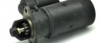
KAMAZ trucks are equipped with a St-142b starter with a voltage of 24V and an idle current of up to 130 Amperes. To start it, you need to turn the key to a non-locking position. As soon as the start has taken place, the key is released.
Its action goes like this:
- The current from the batteries passing through the traction relay engages the flywheel ring gear and the drive gear while simultaneously closing the starter power contacts.
- rotation of the armature is created with transmission of torque to the flywheel through the drive gear.
- they are disconnected after the engine begins to operate in autonomous mode.
Read also: How to change bearings in a VAZ 2114 box
How does it work
After turning the ignition key, voltage is supplied to the additional (PC-530) starter relay. KamAZ remains standing still for now. After the voltage exceeds the 8 V level, the traction relay is switched on.
The mechanism forcibly connects the drive gear with the flywheel ring gear. Also at this time, the starter power contacts close. The anchor begins to rotate. Torque is transmitted to the flywheel. After the engine starts, the gear automatically disengages.
Anchor
As for the anchor, it includes the following elements:
The latter is made from sheets of electrical steel. The manifold is designed to maintain constant torque. The winding is wave type. 2 wires are placed in the grooves with a core.
Moreover, their turns are isolated from the core. The end of the wires is placed in the slot in the copper plate of the collector and soldered.
The main symptoms of a malfunctioning starter
To determine possible starter malfunctions, you will have to pay attention to its behavior, as well as the sounds it makes.
- So, if the traction relay is activated, but the crankshaft does not turn, let's start by checking the battery charge. The reason may be that the brushes or commutator are clogged with dirt and dust. In this case, the traction relay itself may have burnt or oxidized contacts.
- After the engine starts, the starter armature may continue to rotate. This may mean that the relay springs are broken and need to be replaced with new ones. Welding of the contact disc to the bolts may occur. In this case, we will need a KAMAZ wiring diagram in order to clean the disk itself and the bolts, or replace them. If necessary, the starter interlock relay may need to be replaced.
- Another situation is that when you try to start, characteristic clicks are observed that the traction relay makes. In this case, you need to start by checking the contact connections in the circuit of the relay itself and restoring the reliability of the contacts. If necessary, it may be necessary to replace the retractor itself.
Note! There may be no contact between the brushes and the commutator, in which case either the brushes themselves or their springs are replaced.
- If the wiring on the KAMAZ was assembled with a violation of the contact adjustment at the moment of closing, turning on the starter will be accompanied by the grinding of the drive gear. You will need to adjust the gap between the thrust washer and the gear. When you try to start the engine, gears may grind, but the engine will not start.
We visually check the condition of the contacts and wiring harnesses.
This means that the issue may be an incorrectly adjusted moment of closing the contacts of the traction relay . Or the ends of the teeth of the flywheel gear or drive are clogged. In this case, you will have to either replace the gears with new ones or try to restore the teeth. They are reanimated by surfacing.
Tip: At a minimum, try to smooth out any rough spots on them first.
It is possible that the armature continues to rotate, but the crankshaft does not rotate, which means that there is no interaction between them. First of all, check that the starter is adjusted correctly. After this, make sure that the teeth of the drive gears and the flywheel ring are in unworn condition.
We begin to dismantle the KAMAZ starter
In order to carry out repair work, we will need a special stand on which we will disassemble this unit, and a KAMAZ electrical wiring diagram.
The diagram is clickable - 1600x1088
Dismantling this block begins with turning off the ground. If difficulties arise, read the article problem with the “mass” on our website.
After this, we raise the cab and disconnect the wiring that goes to the starter relay.
So, our actions will be as follows:
- unscrew the nuts on the starter housing and on the relay cover;
- remove the jumpers connecting the exciter winding and the output bolt of the traction relay;
- Next, you need to unscrew the nuts securing the traverse, located on the collector side;
- unscrew the lock washers;
- remove the cover from the side of the collector after unscrewing the bolts;
- Unscrew the screws that secure the brushes to the traverse;
- you can finally remove the brushes themselves;
- Unscrew the screw of the adjusting flange and dismantle the lever axis;
- the drive cover is secured with a screw - unscrew it;
- remove the relay simultaneously with the anchor;
- bend the lock washers and unscrew the bolts;
- we dismantle the drive cover simultaneously with the drive itself and the lever;
- We finish by removing the thrust washer, after which the starter armature is removed.
Now the device is ready for diagnostics or repair, if the rest of the wiring on the KAMAZ is in good condition.
What to pay attention to
How to check a disassembled starter
Let's look at the main stages of testing functionality:
Important! If the lamp is on, it means the relay is working properly.
- Checking the starter switch relay. It is located under the fuse panel. We bring “+” to terminal “K”. If there are clicks from the contacts and the indicator lamp lights up when connected to a black wire, this indicates that the switching relay is working.
Internal elements of the starting device
- Checking the device locking relay. It cannot be checked with a conventional test lamp, because... it is assembled from semiconductor devices. Its performance can only be determined using a special device. However, its failure will not necessarily lead to engine starting problems.
- Checking the starter motor. It is necessary to check its serviceability on a stand, in disassembled form. This procedure is the most complex and time-consuming and takes about half an hour.
Read also: Why does the windshield sweat a lot?
As a rule, the performance of this starting device is checked by factors such as the amount of current used and the idle speed. The obtained data is compared with those provided for this type of starter.
Varieties
There are several types of these mechanisms:
The KamAZ starter belongs to the first type of device. This mechanism is the most powerful, since here the transmission of torque from the armature to the gear is carried out by a gearbox. Such starters have not only high power, but also good starting torque. They also have a long service life. These types of starters are used on 90 percent of modern cars.
As for gearless elements, they operate as follows. After voltage is applied to the electromagnetic switch, the Bendix gear moves and engages the flywheel ring. Current flows to the armature. Rotation occurs. The gear and shaft are aligned using a freewheel. After the engine has started successfully, this connection is released. The current supply stops and the gear returns to its original position. Due to low efficiency and low maintainability, gearless elements are practically not used in the automotive industry.