Operating principle
Hydraulic distributors are made of high quality steel, modified cast iron or bronze. Some elements are treated for additional protection: they are nitrided, cemented, etc. Size and weight depend on the volume of working fluid. The more it passes through the system, the more impressive the dimensions and weight are usually.
Let's consider an elementary diagram of the operation of a hydraulic distributor. In the initial state, liquid from the pump does not flow into the hydraulic cylinder. As soon as the operator moves the shut-off and control mechanism in one direction, it begins to flow into the corresponding cavity of the cylinder, causing the piston to start moving. The liquid that the piston begins to displace goes down into the tank. After completing the task, the operator returns the mechanism to its initial position.
The devices can be guiding or throttling. In the first case, the distributor only opens or closes the fluid passages. Throttling models provide the ability to regulate the flow rate. This occurs due to the ability of the locking and regulating mechanism to open the channel not only entirely, but also partially. The advantage of such designs is the absence of sharp shocks when turning the mechanism on/off.
Help in selecting equipment
SUBMIT YOUR APPLICATION
To get a consultation:
Your message has been successfully sent!
Our specialists will contact you soon!
Advantages of using spool valves
Spool hydraulic valves have become quite widespread in the hydraulic systems of special equipment and other mechanisms, as they have a number of advantages:
- Simplicity and low cost of production. The design has a simple design and is maintainable; if necessary, any damage can be quickly repaired.
- Compact sizes. The distribution mechanism does not take up much space, this expands the possibilities of its use in special equipment and other types of devices where hydraulic motors are used.
- Small mass. The distributor does not place a significant load on the main body of the equipment.
- Simple controls. The simplest version has only three positions; the movement of the spool is controlled by signals that are supplied to the magnets.
Simplicity guarantees such a distributor high reliability - if the operating rules are followed, it rarely fails. The working element can be replaced if necessary.
Varieties
Depending on the type of main element, you can buy the following hydraulic valves:
- spool type;
- valve type;
- crane type.
Spool valves
The main element of such distributors is a cylindrical or flat spool. In the simplest scheme, everything happens as we described above. In the “quiet” position, the spool closes the channels. When it moves to the left, the liquid rises into the left cavity of the cylinder, as a result of which the piston moves to the right. If the mechanism is moved to the right, the liquid will begin to fill this side of the hydraulic cylinder, forcing the rod to retract back. The process of returning the piston to its original position is usually faster, since the filling area is smaller.
Based on the number of fluid flow lines, two-, three-, and multi-port hydraulic valves are distinguished. The system control can be manual or hydraulic, electromagnetic or electrohydraulic. When using only muscle power, a button, lever, rotary handle or foot pedal is used. In the case of a mechanical device, the process is started by a pusher, roller or spring. Pressure can be direct hydraulic or pneumatic.
Often the system uses several spools at once. Such designs are divided into monoblock and sectional. If there are several compartments, they are connected with bolts. The shut-off and control mechanism for this type of distributor is available in three versions: with positive, zero and negative axial overlap. Each of them has its own advantages and disadvantages.
The advantage of the first option is the ability to fix the position of the piston. Minus: there is a dead zone within which the actuator does not move even in the presence of a signal. Spools with zero axial coverage do not have such an area. Their disadvantage is the relatively high cost associated with difficulties in manufacturing. Models with negative overlap have a minimal dead zone. The negative factor here is the less rigidity of the structure.
Crane
These hydraulic valves regulate flows by turning the valve plug. The most popular products are cylindrical and conical in shape. Flat and spherical models are also available. One of the most important characteristics of such devices is tightness. Over time, the gap between the plug and the valve body may increase, resulting in leakage of the working fluid.
Users of hydraulic valves with a cylindrical plug most often encounter this problem. Initially, the gap between the surfaces is 0.01...0.02 mm. As the structure wears out, the plug and the body begin to fit together less tightly. You have to either put up with constant fluid losses (after all, they are not too great), or buy a new device. Models with a conical plug do not have this problem, which makes their purchase more profitable.
Valve
Hydraulic distributors, which use a valve as a shut-off and control element, are capable of operating at high pressure. If spool designs are limited to a nominal value of 32 MPa, then valve designs can withstand loads two to three times greater. The flow vector of the working fluid is regulated by sequential opening/closing of the passage channels.
When the motor needs to be activated, the operator moves the rod on which the protrusions are located. As a result of this movement, one of the pairs of valves opens, and the liquid begins to move through the corresponding channel. It either enters the hydraulic motor or is drained into the tank. At the end of the process, the rod returns to its original position.
Valves for distributors can have a variety of shapes, ranging from balls to cones. They are controlled manually, mechanically or electrically. Of the devices driven by muscular efforts, the most widespread are elements with a swinging lever. In many designs, the valves are opened/closed using a cam drive.
The ability of these hydraulic valves to withstand severe pressure affects the dimensions and weight of the products. They are significantly heavier and larger compared to spool-type models that pass the same amount of working fluid. You should also take into account the sharp fit of the valves on the seat. From time to time, serious water hammer may occur, which negatively affects the operation of the entire system and its service life. In view of this, such devices are not recommended for use in structures where high inertia of moving masses is allowed.
Preventing water hammer
One of the disadvantages of using hydraulic valves of this type is the possibility of water hammer due to a sharp increase in pressure at the moment the channel is blocked by the spool belt. Because this happens very quickly, the fluid flow can stop instantly, resulting in a risk of water hammer and damage to the mechanism. To avoid such situations, the distributor is equipped with a safety valve; it is placed in the housing.
Another option for a smoother and safer opening of channels is the use of spools with cone-shaped bands. The cone angle does not exceed 6-10 degrees, but this already ensures smoother operation of the distribution mechanism. As soon as the channel opens, the liquid flows more slowly into the working cavity, as a result, the output link of the hydraulic motor begins to move more smoothly. This design feature prevents water hammer and increases the durability of the mechanism.
More details about the service
Change of oil
The oil in the hydraulic system is usually changed seasonally during maintenance or every 2000 operating hours. However, if low-quality oils are used, or if they are contaminated, an unscheduled replacement may be necessary.
This procedure consists of several important steps:
- Turn on the gear pump.
- Start the engine.
- Warm up the oil in the hydraulic system to 20-30 degrees.
- They turn off the engine.
- The oil is drained through the drain hole of the hydraulic tank after unscrewing the filler neck.
- Remove the filter and housing and wash it in diesel fuel.
- Reinstall the filter.
- Close the drain plug.
- Oil is poured through the filler neck to level “P” in the control window.
- Start the engine and bleed the hydraulic system by raising and lowering the hitch.
- If necessary, add oil to the tank.
Example of a hydraulic circuit for a grinding machine
Example of a hydraulic circuit for a grinding machine
Features and benefits of hydraulic drive
Hydraulic drive is a set of devices (which includes one or more volumetric hydraulic motors) designed to drive mechanisms and machines using working fluid under pressure. Hydraulic drives are one of the most rapidly developing sub-sectors of modern mechanical engineering. Compared to other known drives (including electromechanical and pneumatic), hydraulic drives have a number of advantages. Let's look at the main ones.
- Possibility of obtaining large forces and powers with limited sizes of hydraulic motors. Thus, a hydraulic cylinder with a piston diameter of 100 mm at a pressure of 70 MPa, which can be created by a hand pump, develops a force of about 55 tons, so using special jacks you can manually lift bridges.
- High performance while ensuring the required quality of transient processes. Modern hydraulic drives, for example test benches, are capable of processing a given impact with a frequency of up to several hundred hertz.
- Wide range of stepless speed control with good smoothness of movement. For example, for hydraulic motors the control range reaches 1:7000.
- Possibility of protecting the hydraulic system from overload and precise control of acting forces. The force developed by a hydraulic cylinder is determined by the area of its piston and the operating pressure, the value of which is set by adjusting the safety valve and controlled by a pressure gauge. For a hydraulic motor, the amount of torque developed is proportional to the working volume (overall dimensions of the hydraulic motor) and the effective pressure of the working fluid.
- Obtaining linear motion using a hydraulic cylinder without kinematic transformations (an electromechanical drive usually requires a gearbox, screw or rack and pinion gear, etc.). By selecting the areas of the piston and rod chambers, it is possible to ensure a certain ratio of forward and reverse stroke speeds. An important circumstance is the ideal protection of hydraulic cylinders from external contaminants, which allows the successful operation of hydraulic drives, for example, in mining equipment, excavators and other machines operating in conditions of increased environmental pollution, and in some cases under water.
- An extensive range of control mechanisms, ranging from manual control to direct control from a personal computer, makes it possible to optimally use hydraulic drives to automate production processes in various fields of technology, successfully combining the exceptional power and dynamic qualities of hydraulics with the ever-expanding capabilities of microelectronics and complex control systems.
- The extensive possibilities for energy storage and recovery provide a good basis for the development of modern energy-efficient hydraulic drive mechanisms.
- The layout of hydraulic drives mainly from standardized products, mass-produced by specialized factories, reduces manufacturing costs, improves quality and reliability, facilitates placement on a machine of a large number of compact hydraulic motors (hydraulic cylinders or hydraulic motors) powered by one or more pumps, opens up wide opportunities for repair and modernization.
Avrutin Handbook on hydraulic drives of metal-cutting machines, 1965
Biryukov B.N. Hydraulic equipment for metal-cutting machines, 1979
Leshchenko V.A. Hydraulic servo drives of machine tools with program control, 1975
Sveshnikov V.K Machine-tool hydraulic drives: reference book, 6th ed. reworked and additional 2015
Smirnov Yu.A. Malfunctions of hydraulic drives of machine tools, 1980
Kucher A.M., Kivatitsky M.M., Pokrovsky A.A., Metal-cutting machines (Album), 1972
Areas of application of manual hydraulic valves
Such mechanisms are used directly in the hydraulic systems themselves. With the help of hydraulic valves, the movement of the “working parts” of engines, namely shafts and rods, is controlled. These mechanisms are relevant for:
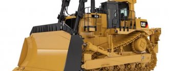
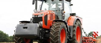
- Agricultural equipment (excavators, graders, bulldozers).
- Stankov.
- Trucks.
- Lifts, crane machines.
Advantages of manual hydraulic valves
- Easy to install and operate.
- Compactness.
- They can operate in both low and high temperature conditions: from –40 °C to 70 °C.
- Depending on the shut-off and control element, they can operate under high pressure conditions.
- With proper use, they will last for several years without interruptions or breakdowns (but it is worth remembering that under extreme conditions, the gaskets cannot withstand, and wear of the rubbing surfaces can lead to leaks).
- Adequate cost.
Possible consequences of contamination
There are two main consequences of the presence of contaminants in hydraulic fluid:
- Decreased hydraulic efficiency. This leads to a sharp decrease in the efficiency of all equipment/machinery. Typically, effectiveness decreases gradually and is difficult to detect if the inspector does not have the necessary knowledge and experience. At a minimum, such an effect will lead to a sharp increase in fuel consumption.
- The presence of contaminants accelerates the wear of parts that make up the hydraulic system. Statistics show that 75-85 percent of malfunctions of the most important hydraulic elements are associated precisely with the presence of contaminants in the fluid used. There are three main types of wear: abrasive, adhesive, and fatigue.
Abrasive type wear
The presence of abrasive particles in the hydraulic fluid leads to scraping of metal from the elements of this system.
This not only accelerates the wear of critical hydraulic components, but also increases the overall level of contamination, which accelerates the occurrence of various troubles. Fatigue-type wear
High pressure and shock loads constantly applied to parts of the hydraulic system cause metal chips to form, which further contaminate the hydraulic fluid.
Adhesive type wear or obliteration
Various particles found in the hydraulic fluid begin to adhere to the metal surfaces of the system. The result is that the valves stop functioning correctly, and the liquid itself cannot circulate effectively in the system.
