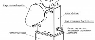
Main assembly units of the dredger
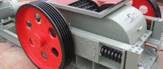
An installation consisting of a soil pump, suction and pressure body slurry pipelines and a soil pump motor with drive.
(Slurry pipeline; Soil pipeline)
The slurry line through which the slurry enters the soil pump.
Part of the suction slurry pipeline that is movable relative to the dredger body.
A specially shaped pipe at the lower end of the suction pipe facilitates intensification of soil intake.
A slurry pipeline through which pulp is transported due to the pressure created by a soil pump.
(casing pressure slurry pipeline, casing pressure soil pipeline)
Part of a pressure slurry pipeline equipped with floats. Previously, metal slurry pipelines with pontoons were used, but recently they are rarely used due to their economic unprofitability.
Part of the pressure slurry pipeline located on land.
In modern dredgers, the more appropriate term is: slurry pipeline section. The portion of a floating slurry pipeline between adjacent joints or sleeves. Lately, this concept is fading away, because... Flexible rubber-fabric pipelines are becoming increasingly popular both in Russia and abroad. Currently, it is more appropriate to talk about slurry pipeline sections that are attached to each other using flange or quick-release connections.
Not used on modern dredgers. The last link of the floating slurry pipeline, connecting to the onshore slurry pipeline. It is also not used in modern hydromechanization, because when using flexible rubber-fabric slurry pipelines, it is not necessary.
Not used on modern dredgers. The hinged connection of slurry pipeline pipes is not currently used, because it is not necessary when using flexible rubber-fabric slurry pipelines.
May not be applicable on modern dredgers. Rotary swivel connection of the suction pipe with the stationary part of the suction slurry pipeline. Not applicable when using suction rubber-fabric slurry pipelines.
(Stern hinge)
A hinge connecting the hull slurry pipeline with the floating slurry pipeline.
(Vertical joint; Gooseneck)
May not be applicable on modern dredgers. The hinge of a floating slurry pipeline having a vertical axis of rotation. It is not necessary when using rubber-fabric floating slurry pipelines.
The outlet narrowed part of the pressure slurry pipeline, forming a pulp stream
(Soil intake device)
The working parts of the dredger for loosening and feeding soil into the suction pipe.
(Ripper; Baking powder)
A device that separates soil from the massif under water and loosens it.
(Mechanical ripper)
(Milling ripper)
A mechanical ripper, the working part of which is a milling cutter.
(Rotary ripper)
A mechanical ripper consisting of one or more rotors with cutting elements mounted on them.
(Rotary bucket ripper)
(Chain ripper)
A mechanical ripper in the form of an endless chain with soil rippers installed on its links without buckets.
(Hydraulic ripper)
(Milling-hydraulic ripper)
Milling ripper that loosens the soil with additional hydraulic erosion.
A ripper that develops soil with a vibrating working body.
(Ripper blade)
Cutting element of a mechanical ripper.
(Ripper tooth)
(Hydraulic ripper attachment; Hydraulic ripper nozzle)
The outlet narrowed part of the water conduit of the hydraulic ripper of the dredger, forming its jet. Note. By water line we mean a pipeline for supplying water from the pump to the hydraulic ripper nozzle.
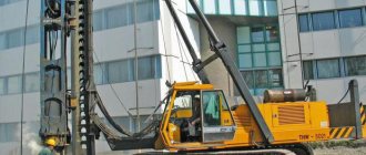
A mechanism for moving the dredger body relative to the pile.
3.33. Working pile
The dredger pile, relative to which its working movements are carried out - papilloning and feeding.
A pile that secures the dredger in the excavation when re-hammering the working pile.
Dredger device
The dredger mechanism includes several main components, each of which is responsible for a separate functional component:
- main group - a soil intake device, a suction pipeline, a pump, a complex for transporting pulp, equipment that moves the soil intake device;
- auxiliary components - the ship’s hull, a mechanism for lifting and lowering, secondary pumps supplying clean water, a set of power supply installations;
- systems that ensure the safe use of the dredger and its performance - the dredger control device, equipment for control and measurement, heating, ventilation systems, as well as fire protection, warning and communication installations.
Dredgers are:
- diesel engines (best suited for cleaning the bottom of a reservoir when it is polluted or when waterways become impassable);
- electric (can cope with harsh operating conditions, suitable for removing sediments in ponds and technical reservoirs);
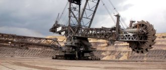
- multi-bucket;
- rod (show good results when performing dredging work in shallow water);
- grab (they cope well with dredging tasks and are used for extracting non-metallic materials from great depths);
- milling, rotary and free suction - the choice depends on the type of soil;
- metal for work at one point of ash pulp discharge;
- rubber-fabric for frequent transportation.
The advantage of a dredger over other types of cleaning equipment is its mobility, small size, environmental friendliness and low operating costs, high energy efficiency, and wide access. This baby can get to problem areas of reservoirs where large equipment simply cannot go. The dredger can be easily delivered to any point, and without special permits from the traffic police.
When is water cleaning necessary?
Before making an accurate diagnosis of the purity of water in a pond, you should understand the categories of possible contaminants:
- Mechanical - are the accumulation of a large number of foreign objects and particles (garbage). In addition to household waste, mechanical pollutants can include unacceptable amounts of sand, clay, pebbles and other things that enter the reservoir.
- Chemicals are various drugs or chemical substances dissolved in water. In this case, the degree of pollution is determined by the level of their con src=»https://fermer.blog/media/res/1/6/0/8/1/0/160810.q2ntgo.jpg» class=»aligncenter» width=»1280 ″ height=”800″[/img]
- Biological — these include a large number of bacteria and microorganisms that were not previously found in local water, and therefore led to an imbalance in the species balance.
The following changes may be the reason for cleaning reservoirs:
- Changes in the color and transparency of water are usually a consequence of eutrophication (saturation of water bodies with nutrients). But there may be other reasons: for example, clay or fine sand leads to cloudy water due to a large amount of suspended matter.
- Overgrowth of a pond with reeds and algae - the accumulation of a large amount of sediment at the bottom makes the pond shallower and promotes rapid warming of the water, due to which the rapid and active growth of various vegetation occurs.
- The appearance of a new (unpleasant) odor is most often the cause of the active reproduction and activity of new bacteria and fungi in the water.
Important! The optimal time for cleaning a pond is May - the period when the “blooming” on the water is just beginning. The recommended frequency of the procedure is 1 year.
Additional possibilities for using dredgers
Each of the above types of work requires its own dredger. For example, for short-term work on construction sites, completely dismountable models are most in demand, the components of which can be transported by rail or road transport.
To solve problems in sand and gravel quarries, dredgers with non-demountable bodies are used, equipped with weighted soil intake devices, slurry pumps and slurry pipelines. This increases the service life of devices under high wear conditions.
Models for sand extraction have a complex design, depending on the conditions of use. For example, if the soil at the site is harder, then a scoop type dredger is more suitable. The extracted sand is loaded into containers and transported to where it is then planned to be finally purified from impurities.
If your task is sand mining, pay attention to the following aspects when choosing the type of dredge:
- waste coefficient during sand mining;
- soil type;
- extraction method;
- mechanism capabilities.
By the way, after the dredger operates, the depth of the reservoir changes, which fishermen need to take into account. If you find out in advance where the work was carried out, you can identify promising places for fishing. In addition, the river, deepened by the dredger, becomes navigable.
Remember that installation and dismantling of the dredger must be quick and simple, and for rapid movement the machine must have a floating base that can be quickly removed if necessary.
has many years of experience in cleaning reservoirs with dredgers. In our arsenal, we have a wide selection of powerful equipment for any occasion, which guarantees our clients a full range of services and excellent quality work.
The price for the work done depends on the depth, width of the reservoir, amount of sediment, soil, but rest assured that the cost of the work will pleasantly please you.
Map of alluvium and geotubes
For proper functioning of the dredger, a water influx of 300 m3/hour is required, for a mini-dredger - 150 m3/hour. Is there no such influx or is the lake small in size? Then it is necessary to make alluvial maps or use geotubes. In both cases, it is important to drain the water back into the reservoir.
Pumping of soil through the slurry is carried out in the following proportions: the ratio of the dry residue to the entire mass of the pumped sediment is 20% - silt in the dry residue, the rest is water, 15% - sand in the dry residue, 7-10% clay, depending on its type. Based on these data, it is possible to determine whether there is enough water in the reservoir so that the dredger does not “sit on its belly” and which dredger needs to be selected for a particular reservoir.
Alluvium map and why it is needed
Alluvium maps represent an area with a slope towards the water body, three faces made in the form of a dam (parapet) and a well with a drain pipe.
The height of the parapet and the area of the map are calculated in each case separately. As a rule, several alluvial maps are used. The width and height of the embankment, as a rule, depend on the specific area, the quality and quantity of the soil being washed. When cleaning reservoirs with a dredger, the height of the embankment of sludge beds can reach tens of meters or even more.
Unlike sand, silt releases water extremely slowly and before the silt sediment falls, a large amount of water can enter the alluvium map. Such water must be kept from spreading. Removal of settled water from the alluvium map is carried out by pumping it out with pumps or using a drainage well.
When hydraulic alluvium, you need to constantly monitor the condition of the embankment of the alluvium map. Streams of water can wash away the base of the embankment, and the contents of the map can spread over thousands of square meters.
Geotubes as an alternative to alluvial maps
Geotubes are cylindrical soil receptacles that are made of high-strength geotextiles (for example, polyester textiles, propylene or polyethylene).
They are intended for the treatment of reservoirs, ports, treatment facilities, sludge ponds, sludge reservoirs, wastewater, agricultural and municipal wastewater and other objects. In the manufacture of geotubes, special technologies are used, due to which pores are formed that allow water to pass through and retain solid particles inside. The principle of operation of a geotube is that geotextiles allow water to pass through, and fine particles are retained inside. This results in the process of dewatering bottom sediment. Geotubes are more often used where it is not possible to construct a map of alluvium, that is, where it is necessary to maintain cleanliness during the work process. The process of draining water from a geotube is much slower than from an alluvial map. In this regard, several geotubes are often used at once, while one is filled, the others are merged
annotation
Designed for deepening and cleaning the bottom of reservoirs and rivers for the reclamation of hydraulic structures and sites, underwater development of sandy, sand-gravel and heavy soils. A quarry machine designed to work in difficult mining and geological conditions. It has a number of modifications: a dredger with a milling ripper, a pressure pile drive and a development depth of up to 10 m, category of developed soils from I_to VII; dredger with a rotary ripper, pressure pile drive and excavation depth up to 8 m, category of developed soils from I to non-category (sandy loam, loam, heavy clay); dredger with ejector head and hydraulic loosening, excavation depth up to 18 m, category of developed soils from I to V.
To date, 235 dredgers have been produced and they are successfully operated in all regions of the Russian Federation in various geological conditions.
Project S-42 suction dredger. 00.00.00.00 Manufacturer LLC “NPO Gulfstream”
Permission to use Certificate of conformity
Sucker dredger
Suction dredger, in accordance with the requirements of project C42-00.00.00.00, as well as the requirements of the “General Technical Specifications for Mechanical Engineering Products” (OST 35-03086), “Rules for the Classification and Construction of Inland Navigation Vessels of the River Register of the Russian Federation”, “Rules for the Construction of Electrical Installations”, “Sanitary rules for inland navigation vessels”, “Unified safety rules for open-pit mining of mineral deposits” PB03-498-02. Dredger type - non-self-propelled, modular, collapsible, navigation area - for vessels class. “O”, electric, powered via an electric cable from a shore disconnector, transportable by rail and road.
Principle of operation
In order to be able to clear the bottom of the accumulated accumulations, the dredger must operate according to the following principle:
- The first step is to carry out calculations that take into account the feed rate of the soil mixture and the permeability of the pipeline system.
- Next, the soil pump is lowered to the bottom of the water body, after first pouring water into it. Includes the motor and gearbox of the dredger.
- Air is pumped out from the suction pipe.
- The resulting vacuum allows water and soil to be drawn inside.
- The soil mixture, which enters the pump pipe, is pumped either into the hold or onto the shore.
- The entire system is set in motion through the use of winches or pile drives. Combination is also acceptable.
Did you know? The largest dredger is the Hurley, which is cleaning up the Mississippi River. The length of its pipeline exceeds 300 m, and the sections cleared at a time are more than 10 m wide.
The control system is located in the captain's room of the dredger vessel. This is where the remote control is located, which gives access to all functions.
Schematic diagram of the suction dredger: 1 - soil intake device; 2 - suction pipeline; 3 - soil pump; 4 - pressure pipeline; 5 - device for working movements; 6 - body.
Firms in Moscow providing similar services
The cost of renting a dredger is from 50 rubles per cubic meter. Hourly payment is 1000 rubles. Company website: fls-gidrostroy.ru. Telephone.
Website: vodokrut.ru. Rent of a specialized amphibious dredger TRUXOR DM4700 with an operator from 2900 rubles per hour. Phone: 8-916-922-59-09. They work seven days a week.
If you are the happy owner of a pond in your garden, keep it clean and tidy. And then it will bring real pleasure to you and your family. The dredgers we described are excellent for deepening and cleaning water bodies.
Types of dredgers
Suction dredgers differ in the following characteristics:
- Productivity per hour:
- especially small (less than 50 cubic meters/h),
- small (from 50 to 200 cubic meters/h),
- medium (from 200 to 500 cubic meters/h),
- large (from 500 to 1000 cubic meters/h),
- especially large (more than 1000 cubic meters/hour);
- Design:
- collapsible,
- non-separable;
- Way to travel:
- on its own,
- not under its own power;
- Soil sampling method:
- with loosening,
- without loosening;
- Control method:
- manual,
- remote,
- automated.
All dredgers are also classified according to the method of moving the pulp, the type of power supply, the number of soil pumps, the location of the main components, and the presence of living quarters on board.
Our company produces dredgers with a soil productivity of up to 160 cubic meters per hour. You can fill out the form using the button below, and we will select the optimal equipment for you.
Questionnaire for dredger
Production of dredgers^
The production of a dredger is a complex of works in which the actual production of the machine is only the final stage.
First of all, the customer fills out a questionnaire and draws up a technical specification, in which he describes in as much detail as possible the requirements regarding the future machine, as well as all the features of the planned dredging or reclamation work.
The design department of the manufacturer studies the technical specifications and the questionnaire, and also analyzes information about the type of soil being developed, the current and waves in the operating area of the designed dredger, climatic conditions, navigability, and the distance to unloading the soil.
In addition, the possibilities of transport delivery of dredger modules to the work site are taken into account.
The information obtained serves as the basis for developing a dredger project, in which, first of all, the type of future machine is determined and justified. Depending on the task and working conditions, this may be:
- dredger with a rotary ripper
: provides high-quality loosening of the soil, but cannot be used on hard rocks. - Dredger with milling ripper
: capable of working with almost any type of soil.
Provides a fairly even bottom profile. Disadvantage
: May interfere with shipping. - free-suction
dredger : instead of a disintegrant, hydraulic erosion of the soil is used, which is then sucked into the slurry pipeline by a soil pump. The best option for developing loose soils. - crawler
dredger : suitable for all types of soil, except hard rocks or soils containing large stones. If waves and currents are below the pontoons, they have virtually no effect on the operation of this machine. Has extremely high mobility and stability. - multi-bucket
dredger: the use of this type of dredger is due to the need to keep the extracted rock relatively dry. Requires a barge or floating conveyor belt for loading soil. Nowadays, it is most often used for the extraction of minerals: gold, diamonds, tin, etc. - Grab or Multi-grab
dredger: The performance of these dredgers depends on the cycle time and bucket volume.
Advantages
: allows mining at great depths and extracting large stones, easy to operate, and has a relatively low cost. - Backhoe Rod Dredger: Great for hard soil excavation. At the same time, it allows you to quite accurately plan the bottom profile.
When developing a project, engineers determine the required dimensions of the working parts and other components of the dredger, select the type and power of the drive, calculate the required lifting capacity of the winch, etc.
At the dredger production site, only partial assembly of the individual components of the machine takes place so that it is transportable.
This point is very important, since an increasing number of projects are being carried out in remote areas with poor navigation. The dredger can only be delivered to such regions by car or rail.
That is why it is so important at the design stage of the machine to provide for the possibility of delivering it by these types of transport
An example of such mobility is the BEAVER dredgers from IHC, individual blocks of which are adapted to international container standards.
The final assembly of the dredger and launching are carried out at the work site.
Dredges (dredgers)
Details Category:
DRIGERS (dredgers)
and machines, tools for excavating and removing significant quantities of soil, ore, coal, etc. Typically, dredgers are used for large jobs when manual work is difficult, slow or expensive. Dredgers are most widely used for dredging and port construction, in railway construction, in open-pit mining of brown coal, chalk, marls, salt, gravel, etc. (see Dredging). Depending on whether the rocks to be extracted are under water or not, dredgers are divided into two types: wet and dry.
Wet dredgers, or dredgers, according to the method of separating and lifting rocks, are divided into two groups: scoop dredgers, which separate the soil using scoops, and suction dredgers, which separate and lift the soil liquefied with water using pumps (see Dredger). When combining scooping and suction bodies in one body, combined dredgers are obtained. According to the method of soil removal, wet dredgers are divided into three groups: trough - unloading soil along short trays into scows; behind-the-scenes - drainage of soil through long gutters, pipes or conveyors; refuler - transporting soil liquefied with water through a long floating pipeline. Finally, these shells are also divided into sea, river and lake.
Dry dredgers (excavators) are divided into the following types: railway, revolving, rope, ratchet, multi-bucket, trencher, drainage, universal, tower, etc. Their further division: single-bucket and multi-bucket, cutting forward and backward, high and low digging. Multi-bucket excavators are also divided into dredgers with free, forced and mixed movement of the scoop chain; In addition, there are bunker and conveyor dredgers, single-port and double-port. Excavators can move on rollers, wheels or tracks.
All dredgers can be equipped with devices for sorting and washing soil, winches for pulling rolling stock, etc. Multi-bucket dredgers are used where an accurate profile of an excavation or slope is required; single-bucket - in narrow places, at greatly varying depths, where the exact profile does not matter. The productivity of dredges generally ranges from 10 to 10,000 m3/h, with machine power from 8 to 3,600 hp. With. The following power units are used: steam engines, internal combustion engines, diesel engines, electric motors. Since in both types (wet and dry) the machines and working parts are generally the same, it is customary to classify dredgers most often according to their operating principle.
I. 3drums with intermittent supply of soil
or other materials are characterized by the fact that their working body (bucket, scoop, grab) has two strokes - working and idle. This group of dredgers includes the following row.
a) A single-bucket projectile (Figs. 1 and 2) is a rotary crane with a boom mounted on a trolley or on a pontoon, but equipped instead of a hook with a gripping device in the form of a scoop, bucket or grab. A typical single-scoop land projectile manufactured by Menck & Hambrock (Fig. 1) has the following device.
The scoop (a) with a sharp cutting edge and teeth is rigidly connected to the handle (b); the bottom of the scoop (c) is folding (or moved to the side); the handle (b), equipped with toothed racks at the bottom, is pulled out by toothed gears (d), which are powered by the machine; the handle is connected to the boom by a clamp (d), which prevents the racks and gears from disengaging in any position of the handle. The scoop is involved in three movements: when the arrow rotates, it describes an arc of a horizontal circle; when the boom and gears are stationary, but when the length of the rope changes, it describes an arc of a vertical circle; when the boom and its upper block are stationary, it can move forward and backward, moving together with the handle using a rack and gears (d). This is the work process. The scoop quickly lowers to the ground with the handle in an almost vertical position, after which, using a combination of two movements (extension with the handle and lifting with a cable), it removes soil shavings. Pulling out by the handle forces the face of the scoop to be pressed against the face. The filled scoop rises to the required height, the boom rotates to the unloading point, the bottom of the scoop opens, and unloading occurs; then follows a rotation to the starting position. The number of complete work cycles is from 45 to 80 per hour.
To perform this movement, three engines are needed: lifting - to lift the scoop, pressure - to press the scoop to the face, rotary - to rotate the boom. For large wet shells, a pull-out machine is added to pull the handle back to the pontoon. Small projectiles make do with 1-2 engines in the presence of gears and couplings. Twin reversible steam engines are most often used as engines; Electric motors and internal combustion engines are also used. Land single-scoop shells are self-propelled; wet ones are rarely self-propelled. A projectile with an arrow that rotates 360° is called a revolver (Fig. 1). A dry projectile with limited rotation (up to 270°), with the rotating part located at the front end of a bogie moving on wheels along normal or narrow gauge rails, is called a railway or standard projectile.
The shells of this group are very diverse both in performance and design. The largest of the latest designs is the revolving dredger from the Marion plant, on caterpillar tracks, with a scoop capacity of 9.5 m3, a boom length of 30 m, and a handle length of 18 m; its productivity is up to 800 m3/h, weight 800 tons. The motors, operating, as in all American dredgers, according to the Ward-Leonard scheme, have the following power: two lifting motors of 250 hp each. s., two rotary 125 l. With. and a 150 hp pressure motor located on the boom. With. In view of the favorable results achieved with these dredgers (by the beginning of 1929, there were about 10 of them in operation), the same plant built (1929) a single-bucket dredge of even larger dimensions, namely, with a scoop volume of 12 m3, with the total weight of the projectile is 1500 tons. One of the small (1927) universal dredgers from the Fundom plant has a scoop capacity of 0.38 m3, three replaceable booms with a length of 4.9, 5.5 and 9.15 m; its productivity is up to 30 m3/h, weight is 14.5 tons, caterpillar drive and 45 liter gasoline engine. With. The projectile is intended for small construction work. In table 1-3 shows a number of characteristics of single-scoop shells.
The performance of projectiles varies greatly and depends on many factors that are difficult to account for. It is very difficult to give an exact relationship between the performance and engine power of these projectiles. Experiments on revolver shells (in Sweden) with electric motors, according to the Bucyrus plant, gave the results given in table. 4.
According to the Orenstein & Koppel plant, a type 8 (steam) revolving projectile, with a lifting (tearing) force of the scoop of 12 tons, operates with a productivity of 25-75 m3/h, given in table. 5.
The last, very common, projectile has 2 engines: 1) pressure - a twin 2-cylinder steam engine; D x H = 140 x 200 mm, 260 rpm, power 30 hp. With. and 2) lifting - like this, but D x H = 195 x 230 mm, 300 rpm, power 70 hp. With.
Boilers for steam single-bucket excavators are usually made vertical, locomotive or locomotive type, for a pressure of 8-12 atm; sometimes superheated steam is used; heating surface - 0.4-0.6 m2 per 1 liter. s., with a lifting machine power of 1-2.5 liters. With. per 1 m3 hourly productivity; the power of the pressure machine is approximately equal to 0.5 of the power of the lifting machine. Electric motors are installed in both direct and alternating current.
Excavators of the type considered dig forward and upward (at a high face) and unload soils and other materials through the bottom of the scoop directly into the rolling stock of a train passing by the projectile or fed to the projectile from behind; sometimes unloading goes into a special bunker or directly into a designated dump site (cavalier).
b) A single-bucket excavator-trencher digs backwards and downwards, i.e. towards itself and below the level at which it stands. The projectile differs from the previous one in the design of the handle and its articulation with the arrow (the latter is made at the end of the arrow); it digs narrow, deep trenches (up to 6 m deep with a width of 0.6 to 1.5 m in one pass). Engine - gasoline, diesel or electric motor of 60-70 liters. With.
c) Single-scoop portal projectile, made by Fr. Krupp in Essen, takes the raised soil onto itself, into its own bunker, through a scoop handle made in the shape of a trench (Fig. 2). This projectile is self-propelled, has a productivity of 30 m3/h, with a digging height of up to 8 m, has a weight of 15-18 tons and is equipped with an electric motor or internal combustion engine; intended for use on coal, gravel, coke, etc.
d) Single-scoop wet projectiles differ from dry ones in that they are mounted on a pontoon (Fig. 3). Digging depth up to 4.3 m; hourly productivity - 95 m3 in sand and 50 m3 in stone; the boom is located in the front or central part of the pontoon.
The pontoon is equipped with lowering anchor piles for “pinning” the projectile to the bottom before starting work. The pontoon is lifted on piles by winches by 0.2-0.3 m and secured in working position with brakes. The capacity of wet projectile scoops is 0.3–12 m3, scooping depth is up to 14 m, productivity is 10–500 m3/h. For large shells with scoops of 4, 8 and 10 m3, the average actual productivity can be taken equal to 115, 270 and 330 m3/h. Engines are most often steam; for small projectiles - oil and gasoline.
e) Grab shells - wet and dry - are an ordinary slewing crane mounted on a ship or pontoon, on a tracked or wheeled trolley, and equipped with a grab.
The productivity of wet grab shells is no more than 60 m3/h, dry – up to 200 m3/h. Machine power - up to 2 liters. With. per 1 m3/h productivity. The number of grab lifts is 45–80 per hour. The projectile is used in cases where there is no uniform work associated with the movement of the projectile, with a minor excavation, heterogeneous soil, when the depth changes greatly, if it is necessary to remove obstacles (pulling out piles, etc.), with a significant depth of work, as well as in in cases where a crane is already available, and the purchase of a special dredger is unprofitable. Within the range of the boom, the projectile operates without movement; productivity depends little on the depth of the excavation. Typical speeds: rotation (related to the center of gravity of the grab) vd = 2-3 m/sec; lift vh = 0.3-0.5 m/sec; lowering vs = 0.8—1.0 m/sec. Denoting by t1 the time (in sec.) for closing the grab, t2 - the time (in sec.) for opening it, l - boom extension in m, α - boom rotation angle, h - total lifting height in m, Q m3/h - productivity, z - number of lifts per hour, η - grab efficiency (0.7 - for light soil, 0.75 - for very light soil, 0.5-0.6 - for heavy soil, 0.2-0.35 - for very heavy soil), γ - specific gravity of the soil, G kg - weight of the grab and chains, ηm. — the mechanical efficiency of the machine and transmission, — the capacity of the grab J can be determined (according to Paulman) as follows:
number of lifts
ascent speed
machine power in l. With.
boiler heating surface in m2
f) Rope excavators (Fig. 4) have a wide future and are dangerous competitors for other single-scoop projectiles. Features of rope excavators: large radius of action (13-50 m), increasing with skillful throwing of the scoop; dumping soil far from the excavation; the ability to remove soil below the level at which the projectile stands; 360° rotation.
The mechanism is similar to a crane; the scoop (a), of a special shape, is lifted by a cable (b). To dig, the scoop is lowered onto the ground in the position shown in Fig. 4, and then tightened with a cable (c); After filling the scoop with earth, it is raised with a cable (b), adjusting the tension of the cable (c) so that the guy (d) supports the scoop in a horizontal position. By releasing the cable (c), the scoop is emptied. The normal capacity of the scoop is 0.75-2.75 m3, the weight of the entire dredge is up to 120 tons, there are two machines: lifting and rotating. The longer the boom, the larger the capacity of the scoop. less; however, there are samples with a scoop of 6.12 m3 with a reach of 45.7 m. Travel is wheeled or tracked; engines - steam, gasoline, electric. One of the latest examples of the Ruston & Hornsby plant has a total weight of 300 tons, a scoop capacity of 6 m3, a boom reach of 36.5 m, a capacity of 300 m3/h, and an engine power of 600 hp. With.
II. Dredgers with continuous supply of soil
or other material are wet and dry.
a) A multi-bucket wet dredger, bagger machine, or dredge, is shown in Fig. 5.
For low productivity, the projectile is installed on a pontoon; for medium and high productivity, it is usually mounted on a self-propelled ship hull. The hull of a ship or pontoon has a slot (a), through which a scoop frame (b) passes, one end resting on a high tower (c), and the other suspended on hoists to a portal (d) that covers the slot. Modern shells most often have a frame in the middle or aft well. An endless scoop chain (d), thrown over two drums - the upper (turus) leading (f) and the lower (g), carries 12-50 scoops. The upper drum receives movement from the main machine (h) through transmissions: belt (i), gear, chain or combined. When lowering the lower end of the frame, the scoops (k) cut into the bottom of the reservoir and, when the chain moves, cut off a layer of soil; tipping over the upper turus, the scoops dump the soil into a soil receiving bunker located in the tower, from where it is transported by one or another device [trays (p), corridors, refulers] to the dump site. In this case, the vessel continuously moves through strong steam winches (l, m, n) and cables attached to anchors (usually 1 stern, 1 main, 4 side), performing the so-called. papillonage. The effective productivity of the projectile in average soil is usually 350-900 m3/h; scooping depth is 2-21 m. Scoops, riveted from thick iron or cast from steel, have a closed bucket shape, tapering towards the bottom, with walls inclined to the cutting plane of the soil at a slight angle. Scoop capacity J = 50–1000 (usually about 600 l), weight G = 50–2750 kg; J/G ratio = 1…0.36; wall thickness 5-25 mm; The cutting edge, made of special steel, is made smooth, pointed or armed with 3-5 teeth. Chain links are steel, cast or forged; bolts and bushings are made of carbon or manganese steel. The scoops are mounted through a link (1 working, 1 idle); link length 400–1000 mm. The upper drum has 4 or 5 sides, the lower one 4-6. Cast steel drums; the top without flanges, the bottom with flanges. The latter has a device for moving along the scoop frame to tension the chain after wear. The scoop frame consists of two riveted I-beams connected by fastenings; The upper end of the frame is mounted on a steel shaft, which rests on supports, sometimes moving, rarely with springs. The chain is supported on the frame by rollers. The length of the frame is selected so that, with a 45° tilt, scooping at a given depth is ensured. The transmission from the machine to the upper turrus is a belt transmission (with a pair of gears) in the case of high-speed machines and a gear transmission (with a vertical shaft and bevel gears) for low-speed ones. The overall gear ratio reaches 1:12. To protect the chain from accidents when the ground collapses on the frame or when the scoops hit an obstacle, a hydraulic or friction clutch is introduced into the transmission, or one of the gears is made with a rim on springs (elastic). The soil is tipped from the scoop through the front edge of the latter into a hopper, where a distribution valve, controlled manually, by winches or by a pneumatic drive, directs the soil to a tray, conveyor, couloir or refuler. Tray tilt angle ≥30°; trays - lifting on cables, for the ability to change the angle of inclination, sometimes rotating in a horizontal plane. Winches are installed on the equipment for papillonage (l, m, n), frame lifting (p), trays (c) and other work. Winches are usually installed steam, reversible, independent; group drive is rarely used, sometimes electric winches are used. Projectile engines are most often steam-powered, vertical, with a speed of up to 325 per minute; locomotives or internal combustion engines are found on small projectiles. Steam boilers are often of the steamship type, with reverse smoke flow; pressure 8-13 atm; On large projectiles, steam superheating is used. The stern and bow of the hull are beveled to facilitate towing; the draft is made as great as possible; the tower is brought to the bottom frames; the walls of the wells are made double; ballast tanks are placed in the bow and stern; Dredgers of this type are made self-propelled, sometimes they have their own dredging holds. With a hull length L and maximum beam B, draft T and midsection height H, the following ratios usually occur: L/B = 5.6-5.8; T/B = 0.2—0.5; T/H = 0.6—0.7; L/H = 6-9. In general, length L = 6–50 m.
For self-propelled propellers, propellers are used on the side opposite the scooping device, or a rear paddle wheel; side wheels are extremely rare. For large projectiles, the propulsion engine is usually independent; for smaller ones, the ship receives propulsion from the main engine.
The usual data of these dredgers; scooping chain speed V = 0.25–0.45 m/sec; the number of scoops emptied per minute is 12-25; the speed of lateral movement of the projectile during papillonage is 3-6 m per minute. Let's call the capacity of the scoop J m3, the productivity of the projectile Q m3/h, the filling coefficient of the scoops η, the chain speed v m/min, the length of the link l m, the number of scoops emptied per minute v/2l, the specific gravity of the soil y1, the specific gravity of water y2, depth scooping t m, the height of the upper turus above the water level h m. Then (according to Paulman) the capacity of the scoop
(where η = 0.6-0.7 for sand and 0.8-0.9 for silt) and the power of the main machine in hp. With.
Here, coefficient k is the ratio of the power of the main machine to the required power for lifting from the bottom to the tour; its values, according to Paulman, are given in table. 6.
In practice, 0.4-0.6 liters are often taken. With. per 1 m3/h of excavation. According to Zhirukhin’s research, the machine’s power is distributed as follows: 35% for overcoming the friction of the mechanism, 25% for separating (cutting) the soil, 40% for lifting the soil. During operation, the power of the machines varies from 50 to 260% of the normal average. The heating surface of boilers that satisfies such a load is taken to be 0.35–0.45 m2 per 1 liter. With. power of the main machine.
The equipment and armament of large shells includes: a repair shop, an electrical installation, fans, washing devices, searchlights, a steam wheel, fenders, bollards, fairleads, cleats, beams, boats, a kitchen, cabins, tanks, etc. One of the large modern shells (English, Sir William Matthews, 1925), adapted for unloading on the open sea, even on waves, has a productivity of 1000 t/h, with a digging depth of 13.73 m.
b) Multi-scoop excavators (dry dredgers) are very similar to wet dredgers of the type considered. The projectile is placed on a platform or portal with a wheeled or tracked drive and moves at an operating speed of 0.03-0.12 m/sec. The scoop frame - straight or broken, on hinges - is located on the side (Fig. 6) or at the back, like a trencher, for low or high digging; sometimes there are two frames at once - for low and high digging - both on one side of the projectile or one on each side.
The lower end of the frame is suspended by cables, chains or strings, with or without a buffer, from a fixed or movable boom and is controlled by a winch. The weight of the frame is balanced by the appropriate arrangement of machines, conveyors, soil bins and a permanent or movable counterweight. Large projectiles are usually non-rotating, while small ones sometimes have an upper part that can be rotated through 360° (Fig. 7).
The scoop chain runs at a speed of 0.4 to 0.6 m/sec, having a forced stroke (Fig. 8), free (Fig. 6) or, with a cranked frame, sometimes mixed; scoops cut when moving backward, sometimes when moving forward.
The shape of the scoop can be closed, used for short-chain, forward-cutting projectiles, and open, without a back, for all backward-cutting ones (Fig. 6-8). In the latter, the soil is poured out through the open back side of the scoop when the latter approaches the upper turus, and turns over through it, in contrast to wet projectile and short-chain scoops with closed scoops, which dump soil through the rear upper edge, overturning over the upper turus. The scoop is placed on every 4-12th link of the chain, depending on the type of soil. Loading of soil into the rolling stock occurs from a side bunker or through a portal (Fig. 6-8) or along a conveyor (Fig. 9 and 10) with or without a dump cart.
For orientation in the table. 7 shows data on shells from the Lubecker Maschinenbaugesellschaft Co. plant.
The projectile shown in Fig. 9, built by the Putilov plant, in the amount of 7 units. for the East Amur Railway; the projectile is steam, with a capacity of 100 m3/h, with scoops with a capacity of 100 liters, with a frame 14.5 m long and a conveyor for soil. In fig. 10 shows a reloading excavator for reloading and transferring masses transported by trains into an embankment up to 20 m high above the level of the excavator.
Projectiles of this type have a capacity of up to 1500 m3/h and a conveyor length of up to 60 m; they often have a rotating upper structure (220° or more) and a conveyor tilting in a vertical plane; their movement is wheeled, on 4 rails, with the number of wheels up to 64 (8 bogies); Electric motors are used as the driving force. The soil to be reloaded is dumped from the railway cars at (a), then it is captured by a scooping chain (b), driven by a motor (c), and dumped into a hopper (d); from there, along the conveyor belt (e), the soil is supplied to the loading end of the conveyor belt (f). The latter is driven by a motor (g), and rotation is transmitted to the upper tension drum (k) using a worm gear (at the motor), a long shaft, and a pair of bevel (h) and cylindrical (i) gears. The entire upper part of the projectile with the arrow rotates around a vertical axis; a motor (l) is used for rotation. The inclination of the boom (m) is changed using hoists (n); its weight is balanced by a counterweight (o) of 28 tons. An electric winch (p) is used to change the digging depth of the scoop chain. The device (p) shown in dotted lines is used to scoop up the soil falling from the conveyor to the foot of the dump. Such shells are built by the F. Krupp plant.
Excavators of the types considered are built with steam engines, electric motors and internal combustion engines, often with locomotives; steam boilers are made vertical or locomotive type; transmissions are used by belts, chains, gears, and less often friction ones; power standards are approximately the same as for wet multi-scoop dredgers; frame length reaches 50 m.
c) Dredge pumps have a suction pipe as a working element, through which the soil, along with three to six times the volume of water, is sucked by a strong centrifugal pump.
d) Combined wet projectiles are made up of scooping and sucking or sucking and cutting. Such projectiles, working with one of their organs, depending on the soil and the requirements of the work, divert the soil along chutes, couloirs or refulers. Of the new designs, the American Ronaldshay projectile, designed for digging riverbeds, is interesting; the projectile has suckers and 6 cutters for digging trenches up to 13.75 m wide and up to 9.15 m deep; suckers and cutters operate independently. During official tests, the projectile was removed in 40 minutes. 4100 m3 of soil, which corresponds to 6150 m3/h, and dug a new channel 91.5 m long, 12.2 m wide and 3.31 m deep.
The economic benefits of using dredgers depend on the correct selection and application of these projectiles. In the practice of pre-revolutionary Russia, there are the following developed data on the executive cost of dredging work: on the Volga River (in 1911–15), with multi-scoop shells, the average cost of extracting 1 m3 of soil was 29–36 kopecks; on the Dnieper River (in 1911-15), with dredgers, - 9.2 kopecks; on the Svir River, with single-scoop dredgers, on rocky soil - 1 rub. 56 kopecks per m3. Multi-bucket land excavators for 3 years of operation (in groups and alone) on the East Amur Railway showed the following production cost: 1 rub. 10 kopecks per m3 on heavy lipuns, 41 kopecks. - on loams, 17.5 kopecks. - in sand quarries. The above costs include all expenses for excavation and maintenance of excavation equipment, repairs, depreciation and interest on capital. The cost of dredging in the ports of the USSR, according to the estimates of the NKPS, but according to the “Water Transport” (No. 1, 1925), was determined to be 48.1 kopecks. per m3 for the Arkhangelsk port, 30.9 kopecks. for the Volga-Caspian Canal and 18.5 kopecks. for the Mariupol port.
In Germany, executive costs, including all expenses, before the war of 1914-18. were: 0.3 marks per 1 m3 for single-scoop wet dredgers, 0.25–0.30 for grab dredges, 0.15–0.40 for multi-bucket wet dredgers, 0.24 for dredgers, 0.09–0.12 for multi-scoop excavators.
According to R. Mersch, the cost of developing 1 ton of ore with single-bucket excavators in America, according to the annual reports of the companies, taking into account all expenses, including the maintenance of the boards, was (in dollars):
For other companies, the cost is close to the indicated one.
Source: Martens. Technical encyclopedia. Volume 8 - 1929
- < Back
- Forward >
Sand mining in shallow waters
The first method is dry mining. In this approach, sand is extracted from a quarry. Here, characteristic methods and techniques are used for open-pit mining of any minerals. First, they drill wells, then loosen them with explosives, and only then load them onto trucks and transport them to factories and enterprises.
The second method involves extracting sand from the bottom of a reservoir (lake, river, shallow sea). In this case, a special design is used - a sand dredger. Also, as an option, you can use long-arm excavators, excavators with a throwing bucket. However, such equipment is expensive, which affects the final price of the material.
Mining can also occur in wet conditions using hydraulic scouring. This method does not require blasting or drilling. It has an advantage over competitive methods - the extracted sand is free of impurities.
As noted above, on rivers, lakes and shallow seas, a dredge is used to extract sand. The principle of operation is as follows: a device with pumping equipment sucks in sand that is located at the bottom of the reservoir. Next, it is loaded into the hold of a ship or onto a barge. The most convenient for this method of extraction are dry reservoirs.
Concept of dredger
A suction dredger is a floating craft that pumps slurry (a mixture of water and soil) using a powerful pump through pipes into the hold or to the shore.
The vessel has all the necessary equipment for use for the following purposes:
- cleaning reservoirs from silt deposits, sludge, sand;
- deepening the bottom of reservoirs;
- cleaning septic tanks of agricultural or industrial enterprises;
- construction of embankments for various purposes (beaches, roads, squares, etc.);
- development for the extraction of sand and gravel materials, precious metals, sapropel;
- development of slag and ash storage tanks for industrial enterprises;
- installation of trenches for pipelines or for their further washing.
This equipment is also used in the construction of ports on rivers and seas, dams and other important hydraulic structures, eliminating the consequences of floods and reservoir spills, and strengthening the coast.
Source2
A mini-dredger is a device for cleaning small bodies of water. Using a dredger you can:
- Restore abandoned beaches and create new swimming areas;
- Deepen the existing reservoir;
- Clean small lakes, ponds, rivers and canals;
- Wash the reeds;
- Build dams with embankments.
Having a small size and good performance, the mini-dredger is capable of working in such reservoirs where access to large equipment is impossible. For example, on ponds and lakes with an area of up to several hectares or on rivers for work in a specific area. However, it is impossible to completely remove aquatic vegetation with a dredger, just like industrial equipment, but it is quite possible to erode the soil where the root system is located. After this, you just need to collect all the algae mechanically or manually.
The operating principle of a mini-dredger of the soil pump type.
A platform filled with air (float means) freely moves the soil intake mechanism through the water. The dredger has an elongated flexible muzzle with different types of blades (depending on the soil). The blades are used to loosen the soil and the root system of plants (for example, reeds). The sucked soil-containing mixture (pulp) is transported through a slurry pipeline to the shore.
Operating principle of multi-scoop dredger
A multi-bucket dredger is a vessel with a mechanism that holds and drives a closed chain of links with buckets placed on them. When the drive mechanism rotates, the links with the buckets rise to the surface, taking with them part of the soil from the bottom. In the highest position, the bucket turns over, feeding soil to a special outlet tray or conveyor leading to a soil removal barge. After this, the process is repeated. The capacity of such buckets varies from 0.05 to 1 cubic meters, and depends on the type of soil being developed, the drive power, the depth of the fence and the size of the vessel itself. The development depth of a multi-bucket dredger rarely exceeds 20 meters, due to the large weight of the soil-extraction mechanism.
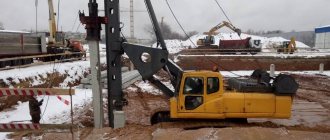
Operating principle of a rod dredger
A rod (single-bucket) dredger is essentially a hydraulic excavator located on a pontoon. Such a floating installation is widely used when carrying out dredging work in shallow waters. The main feature of such a mechanism is its versatility: the excavator can carry out dredging work, compact bulk soil with a bucket, move by pushing and pulling with a bucket, raise and lower anchor piles.
Working principle of grab dredger
A grab dredger is usually created on the basis of a universal unit of the technical fleet - a floating crane. The main working tool of such a dredger is a grab, or a mechanism consisting of two buckets. The grab is attached to the crane boom using steel cables. Grab dredgers can perform dredging work, but are typically used to extract non-metallic materials from great depths. After rising above the surface of the water, sand or sand is conveyed to the barge by a grab. Moreover, there are combined versions - a grab installation with a soil receiving compartment. Such a vessel is capable of loading itself in the middle of a body of water, approaching the shore and unloading.
Source
Dredger for mining, deepening and cleaning. “Boatswain 400”. suction dredger
Comparative characteristics of the dredger and mini dredger
| dredger | Mini dredger | |
| Sludge capacity | 300 kbm. per shift | 150 kbm. per shift |
| Sand performance | 200 kbm. per shift | 100 kbm. per shift |
| Clay performance | from 70 to 120 kbm. per shift | from 40 to 70 kbm. per shift |
| Soil development depth | up to 5.5 meters | up to 4.2 meters |
| Delivery in both directions to A-108 | 350,000 rub. | 40,000 rub. |
| Rent price | RUB 95,000/shift | RUB 35,000/shift |
We offer rental services for various types of dredgers, as well as auxiliary equipment to perform the following work in Russia and neighboring countries:
- Dredging the bottom.
- Cleaning of reservoirs.
- Improvement of the banks, sand washing.
- Excavation work from water.
- Laying and repairing pipelines in swampy areas.
The company's park includes:
- amphibious excavators (Waterking, Big Float, Volvo with TOPCON 3Dxi positioning system);
- long-arm excavators (Doosan);
- dredgers (Watermaster, “Akhtarets”, “Tsimlyansk” (Ts480D));
- small barges, tracked dump trucks.
You can rent equipment in any configuration at a time convenient for you at a price of 3,500 rubles/hour or from 90 rubles/m3 (depending on the type). Modern high-tech equipment allows you to carry out work quickly and safely, without harm to the environment.
We also offer spare parts for dredgers and excavators. Prices are listed in the Sale section.
For more information about cooperation, please call: +7 (800) 555-97-40, +7.