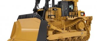
A rotary excavator is a self-propelled machine on a walking rail or track, which is designed for mining minerals and rocks, developing canals, stripping, deep and surface digging.
Such equipment is indispensable when carrying out mining operations, both closed and open, as well as for laying oil pipelines, water pipelines, gas pipelines, trenches and cables. To gain access to deposits of valuable minerals, there is a need to open and remove surface rocks, which requires the presence of rotary equipment.
Classification of machines and units
Multi-bucket excavators differ in design and technical capabilities. Depending on the functions they perform, they can be stripping or mining. Both the first and second ones carry out the development of the soil. Based on the direction of the working field, they are divided into longitudinal or radial digging models. In areas of varying complexity, the methods of approaching the buckets to the soil may change: rock is removed, the earth is removed using upper or lower scooping.
There are special trench type rotors:
- plow-rotor, moving in one direction;
- high-speed trench complex for military purposes;
- screw-rotor.
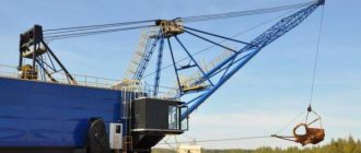
For open-pit mining, the ideal option is a rotary (quarry) excavator.
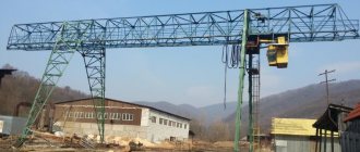
According to the method of movement, they are combined into two large groups: self-propelled (on tracks and rails) or mounted (attached to a tractor-tractor).
Design features
Rotary machines differ in the design of their chassis. In particular, models are manufactured on caterpillar or rail-walking tracks. High productivity of equipment is not the only advantage of rotary machines. A continuous operating cycle makes the operation of equipment more financially profitable. It is worth noting better emptying of buckets and minimal loss of developed soil.
For the models under consideration, the buckets are located on a large wheel (rotor). This ensures that the soil is developed in the optimal direction. If the surface layer is produced, the rotor rotates in a clockwise direction. When working with the bottom layer, rotation occurs in the opposite direction. In addition, the buckets can rotate in a vertical or horizontal plane.
Soil is collected into buckets according to a standard scheme; however, containers are emptied according to the following principles: inertia or gravity. In the first case, the rock in the bucket is affected by a centrifugal force, which throws the soil out of the container. With the gravity method, unloading occurs due to the own weight of the excavation.
Rotary excavators can operate in any climatic conditions. At the same time, the operation of the machines occurs without unnecessary costs and loss of productivity.
Applications and performance
A rotary trench excavator is in demand in the construction of gas pipelines, sewer and collector communications, when laying underground communication systems over kilometer distances, and when digging shallow pits. It is convenient for them to carry out excavations during excavations or large-scale repairs and rescue operations.
An open sand or clay quarry and a bucket wheel excavator cannot be thought of separately. The machine is capable of extracting and shipping bulk solids at a height of up to 25 m and at a depth of 5 meters. They are also used in the direct development of coal faces, when it is necessary to open the soil layer, ship finished products or dump rock.
The main common feature of all excavators of this type is the possibility of uninterrupted round-the-clock operation with high productivity rates, and use in hard-to-reach areas. Climatic conditions, increase or decrease in temperature do not affect quality. Such a cycle is beneficial for the extraction of ore minerals and natural building materials. Save money; thanks to the design of the buckets, losses during loading are minimized.
History of creation
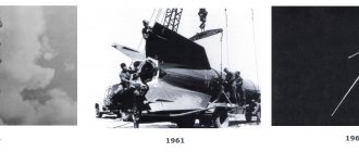
The idea of digging wheels was expressed at the beginning of the sixteenth century by the famous scientist Leonardo da Vinci.
However, the prototype of a modern excavator, equipped with a pair of rotary wheels located symmetrically with respect to the conveyor, was patented by the American engineer C. Smith only at the end of the nineteenth century. Today, the industry for the production of such equipment is developing through the production of machines with high productivity, as well as increased specific force, with the help of which the process of digging trenches and mining minerals is carried out.
Similarities and differences between designs
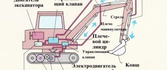
The operating principle and design of rotary excavators are the same for most mechanisms. They represent a single system and consist of a rotating platform to which important components are attached: the chassis, a cabin with a control panel, a superstructure with masts, a moldboard and rotary boom with a conveyor belt.
The difference is significant only in:
- the number of buckets, the diameter of the circle to which they are attached;
- boom length;
- placement of the superstructure;
- the footage of the blade, its rotations and the tonnage of the counterweight;
- engine power;
- methods of unloading buckets (from centrifugal force or from gravity) and in movement.
There are minor differences between the modifications, expressed in bucket capacity, depth, and digging height. They affect how the units are used.
Varieties
Multi-bucket machines are qualified according to their intended purpose. Thus, trench and quarry machines can be distinguished.
Quarry excavator. The equipment refers to multi-bucket continuous machines, although there are also single-bucket modifications. This category is divided into stripping and mining models. The production of material occurs by shallow or deep scooping. The equipment is designed to develop soil up to category 4 of complexity, without preliminary loosening. Used in sand quarries, mining, and rock production.
Quarry excavators consist of individual units combined into one circuit. If one unit fails, there is no need to disassemble the entire machine; it is enough to carry out unit repairs in the field.
Trench excavator. These are machines of wider application. They are used to form trenches for various purposes: for utilities, gas or oil pipelines. In addition, the machines are designed for laying irrigation canals, drainage and drainage systems. It is worth noting that the basic buckets can be replaced with a milling cutter or scrapers.
Technical parameters of the units
The characteristics of types and models differ in digital indicators. You can take average or specific numbers as a basis, but each type is equipped with a telescopic (folding) or stationary boom, at the end of which a rotor rotates. Its position is secured using a winch and cables passed between pulley blocks on the masts. On the opposite side there is a similar dump boom. The mechanism for lowering and raising them follows the same pattern; the hovering angle is regulated by counterweights. These parts together form a superstructure that can rotate around its axis by 360°. This significantly expands production possibilities. The unloading unit (conveyor) has an autonomous rotary mechanics with a deflection angle of 270°, which simplifies the laying of access roads for transport. The operating principle of quarry and trench units is almost identical.
With an average rotary wheel size of 18–20 m in diameter with a bucket capacity of 12 liters, a working depth of 25 meters and double the height, the productivity will be up to 10 thousand m3/hour.
Equipping the transmission with a hydraulic motor simplifies changes in stroke speed from 3.5 to 120 m/s. The bucket chain moves stably and evenly from 0.75 to 1.06 meters per second. The self-propelled excavator is capable of developing 4 transport speeds: minimum 1.25, maximum 7.60 km/h.
The question of why a rotary excavator is needed disappears. Multi-bucket machines perform all mining, loading, and unloading operations simultaneously. One action smoothly transitions into another, forming a circular cycle.
Gears
Gears are designed to change rotation speed and torque.
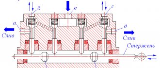
Cylindrical gears transmit torque between parallel shafts (Figure 10a, 10b, 10c). Spur wheels are used at low and medium speeds, when dynamic loads from manufacturing inaccuracies are small or when axial movement of the wheels is necessary. The main types of cylindrical gears: spur; helical; chevron; internal.
Helical wheels (Figure 10b) have a smoother ride and are used for critical mechanisms at medium and high speeds. The disadvantage of helical wheels is the presence of axial forces that affect the operation of bearings that compensate for these axial loads.
Chevron wheels (Figure 10c) have increased smooth operation, but do not cause axial forces, which are mutually balanced and are not transmitted to the bearings. Suitable for transmitting high powers with shocks occurring during operation.
Internal gear wheels (Figure 10f) rotate in the same directions and are usually used in planetary gears.
In rotation transmissions between intersecting shafts, the gears have a conical shape. The work of the transmission can be compared to the rolling without slipping of two cones with their vertices at a common point (Figure 10d, 10e). Bevel gears can have straight, oblique and curved teeth, the latter providing greater smoothness of the transmission.
Figure 10 – Types of gears: a) cylindrical spur; b) cylindrical helical; c) chevron; d) conical spur; e) conical with a curved tooth; e) spur gear with internal gearing
Transmissions between crossing shafts are carried out by screw and hypoid wheels, a worm pair, and a globoid worm pair (Figure 11).
Screw wheels | Worm-gear |
Globoid transmission | |
Figure 11 – Transmissions between crossed shafts
Damage to gears
The main defects of gears are: chipping of metal on the working surface of the teeth; cracks of any nature and location; wear of teeth by thickness; wear of the bore and keyways.
The greatest wear of the working surfaces is observed on the legs of the teeth, where maximum sliding occurs. The fastest-growing type of damage, destruction, begins with the formation of a crack and ends with chipping or breaking of teeth. Cracks begin to appear at the base of the teeth on the side of the stretched fibers and are located perpendicular to the working surfaces of the teeth. The occurrence of cracks leads over time to the destruction of teeth and often to damage to other parts of the mechanism due to pieces of teeth getting into them.
Small clearances in gears lead to increased vibration and noise. In this case, the drive wheel tooth stem is cut and sharp edges appear on the tooth heads.
In worm gears, the threads of the worm wear out much more than the teeth of the worm wheel. In cylindrical gears, gear teeth wear more intensely than wheel teeth.
In open and closed gears, check the wear of the working surfaces, the presence of cracks, chips, breakages, irregularities in the correct engagement, gaps, end runouts, shaft displacements, and the presence of lubricant on the friction surfaces.
The performance of gears is ensured by: the absence of tooth defects and the geometric parameters of gears; correct relative position, regulated by the size of the contact patch; regulated value of lateral and radial clearance; fixed connection of parts.
The world's monster bucket wheel excavators
A large mining machine operates in Germany near Cologne at the Hambach mine. Bagger 288 has a height of 94 meters and a length of 220 m. A huge wheel with a diameter of 32 m weighs 13,500 tons, and is mounted on a 60-meter boom. The productivity of the giant rotary excavator is 245 thousand m3 per day. Capable of digging coal from a depth of 100 m. Moves along the surface on 12 tracks. Their dimensions (height 3, width 3.5, length 15 meters) are calculated in accordance with the total weight.
The miracle of technology is maintained by a team of 5 people. Work on one field continues as long as it is feasible and profitable. The main difficulty is to maintain the balance of the rotor and the correct direction when moving to avoid swinging. In addition, it is very important to choose a flat surface.
The Bagger 293 can compete with its relative. It was built in 1995 for the formation of quarries and operates continuously for 3–5 days. Included in the Book of Records as the owner of the largest mechanism.
People never cease to be amazed at how it works. It turns out that you just need to follow safety rules and have engineering knowledge, and servicing such units will not be difficult.
The advantages of using it are obvious. A long service life (60–70 years), enormous volumes of work and the number of functions performed quickly pay for the costs of construction and technical support.
Seals
Seals are devices that prevent or reduce the leakage of liquid or gas through the gaps between machine parts, as well as protecting the internal cavities of the mechanism from the penetration of dirt, dust, moisture, etc. There are two groups: fixed (Figure 12) and movable (Figure 13) sealing devices . Seals have small dimensions, but at the same time perform important functions. Damage to seals is associated with lubricant leaks and contaminants entering the mechanism.
| Gasket Installation | Installing the round rubber ring |
1 – installation nut; 2 – sealing ring; 3 – protective (fixing) washer | Conical filler plug |
Figure 12 – Seals of fixed joints
| Gland packing | Installing the cuff |
Sealing with rubber O-rings | Felt ring |
| Mechanical seal with bellows | Labyrinth seals with radial channels |
| Oil slinger ring | Throat seal with concentric grooves |
Figure 13 – Sealing of moving joints
Element for connecting shafts
Elements for connecting shafts - couplings: gear, elastic-bushing-pin, balloon, etc. (Figure 16). Couplings are designed to connect shafts. located on the same axis or at an angle to each other and transmitting torque. The coupling (with the exception of a rigid flange coupling) allows compensation for angular and radial displacement of shafts within the limits allowed by the design and dimensions.
Flange coupling: 1 – bolt; 2 – nut; 3 – washer; 4 - bolt; 5 – half coupling | |
Gear coupling | Spring coupling: 1, 5 – coupling halves; 2 – serpentine spring; 3 – screw; 4 – casing |
Bush-pin coupling: 1, 4 – half-coupling; 2 – finger; 3 – bushing | Balloon coupling: 1 – toroidal shell; 2 – half rings; 3 – rings; 4 – screws; 5 – half coupling; 6 – screws |
Figure 16 – Couplings
The performance of couplings is ensured by the integrity of the parts; alignment of mating shafts, uniform wear of elements within acceptable limits; immobility of the coupling halves relative to the shaft (for fixed couplings).