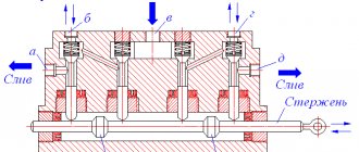
Operating principle of an electromagnet
DC crane lifting electromagnet.
(I haven’t met any others). The particles that make up iron and its alloys are microscopic magnets (called dipoles). However, if the iron is not magnetized, the directions of the magnetic field of these magnets are directed in different directions and the magnetic fields cancel each other (their total magnetic field is zero). The electromagnet coil has an iron core; in addition, the electromagnet also has other steel or cast iron parts - the body, the sole. When current begins to pass through the magnet coil, the dipoles in the iron, steel, and cast iron rotate so that their magnetic field coincides with the magnetic field of the coil. The coil is positioned so that its field is directed perpendicular to the base of the magnet. The total magnetic field of the coil and the dipoles rotated under its action is many times greater than the magnetic field of one coil. What is the effect of this field? Each magnet has two poles - north (indicated by the letter N in the figure) and south (S). The north pole tends to attract the south poles and repel the north poles of other magnets. The smaller the distance, the stronger the magnetic field. If the opposite pole of another magnet is closer than the same one, the force of attraction will exceed the force of repulsion, and this magnet will be attracted.
What happens if the sole of the electromagnet approaches the iron weight? Look at the left half of the picture above. The dipoles in the load will rotate under the influence of the magnetic field of the electromagnet, and they will rotate so that their magnetic field will attract the load to the magnet.
What happens if you change the direction of the current in the electromagnet coil? Let's look at the picture, the half on the right. The direction of the magnetic field will change to the opposite. The dipoles, under the influence of the changed field, will turn again, but in the opposite direction. And in the load the dipoles will turn in the opposite direction. However, their magnetic field will, as before, attract the load to the magnet.
Why am I describing this in such detail here? To summarize: the action of a DC electromagnet does not depend on the direction of the current, and therefore on the polarity of the connection. I hope it has become clear to you why the polarity of connecting the DC contactor coils does not matter.
I don’t know about you, but it became clear to me why lifting magnets operate on direct current. If the current were alternating, the dipoles in both the magnet and the load would rotate back and forth following each change in the direction of the current. Along with the position of the dipoles, the direction of their magnetic field would also change. A change in the magnetic field causes a current to occur. Currents would circulate in both the magnet and the load (they are called stray currents). From them both the magnet and the load would heat up. The movement of dipoles and stray currents would result in a waste of energy, so the energy consumption would be greater. In addition, since the direction of the magnetic field would change all the time, its strength would also change, passing through the zero point with each change in direction. Therefore, the magnet's attractive force would be less than that of an equivalent DC magnet. Probably for the same reasons, DC contactors are more often used in taps rather than AC.
What happens when the current supply to the electromagnet coil stops? The dipoles will return to their previous multidirectional position. But not all and not to the fullest extent. Some will retain a position that, to one degree or another, coincides with the direction of the magnetic field that the coil had. As a result, the magnet will have “residual” magnetism, that is, it will continue to attract the load, although not as strongly as during the passage of current. To make residual magnetism disappear, current is briefly passed through the magnet coil in the opposite direction.
By the way, a DC contactor also has residual magnetism, although perhaps insignificant. But the contactor is designed like a scale, where there is a heavy load on one pan and a light one on the other. The contactor switches off due to gravity, despite residual magnetism. Residual magnetism also occurs in the REV relay. On the part that is attracted to the coil (I don’t know what to call it correctly: rocker arm? lever?), on the side that is in contact with the coil there is a plate made of a copper alloy that is not magnetized (diamagnetic plate). Since the strength of the residual magnetic field is very small, and the field itself weakens with distance, the thickness of this plate is sufficient to prevent the relay from “sticking”. This plate wears out from constant impacts when the relay is activated. Its integrity must be monitored and replaced if necessary. It is convenient to look at it with the help of a mirror.
How to choose a lifting magnet
Selecting the right type of magnetic grip is not the easiest thing, because you need to know which type of magnets is most effective in each specific case.
The choice depends on many parameters and the final decision is always individual. In order not to make a mistake with your choice, seek advice from the specialists of 22VEK Group of Companies. Having many years of experience in supplying equipment from the world's leading brands, we are ready to work out your technical specifications in detail and select a magnetic gripper that will meet all your requirements.
Rectifier for electromagnet.
I present here a rectifier circuit for powering the lifting magnets of one of the cranes that I serviced. It has four magnets, and it uses them to pull long steel beams. I have often encountered such rectifiers, not only in power supply circuits for magnets, but also in operational circuits. There is a lot in his scheme, although not everything is obvious. P3 is an overcurrent relay that protects the circuit from overload (but does not protect against the load falling when it is activated). Capacitor C4 and resistance R4 connected in series with it form a so-called RC circuit. What is it for? The fact is that the rectified voltage, which is obtained directly after the diodes, does not quite correspond to the name “constant”. It's pulsating. The capacitor reduces fluctuations in the rectified voltage. When the voltage increases, the capacitor charges, when it decreases, it discharges and thus smoothes out the ripples. Resistance is needed in order to obtain the required charge and discharge speed. As for RC - circuits and capacitors that are connected between the phases before the diodes, then, I admit, I don’t know exactly what they are needed for. I will, however, present one version. When the crane is moving, you can see sparks flying out from under the shoes of the current collectors. This occurs due to unevenness, oxides and contamination of the surfaces of the trolleys and shoes, as well as crane accelerations. That is, the shoes do not fit tightly to the trolleys at every moment of movement. Therefore, when the crane is moving, the voltage quality on it is worse than on trolleys. Capacitors and resistors are probably included in the circuit to smooth out sudden changes in AC voltage due to poor contact of the shoes, and as a result, increase the stability of the DC voltage. Let us now move on to the description of the actual power supply circuits for the electromagnets.
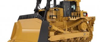
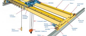
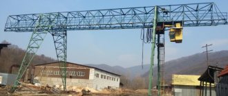
Magnetic overhead crane
Scope of use – lifting and moving raw materials and materials made of ferrous metal with magnetic properties. Cranes are used in enterprises that trade in ferrous metal products or process scrap. Also used at customs terminals and metallurgical plants. They are controlled from the cab, via a push-button remote control or using a radio control system. Depending on the operational requirements, you can choose a span length in the range from 16 to 42 meters. The device is capable of lifting loads to a height of up to 100 m. The lifting capacity of cranes varies from 10 to 40 tons.
Circuit without time relay
This scheme is often found on the Internet under the name “PMS-50”. When the crane operator closes the contact of controller K, power is supplied to the contactor coil B. B(1) and B(2) are closed. Voltage begins to flow to the electromagnet coil. simultaneously B(3) opens. The current flows not only through the electromagnet coil, but also through resistances R1, R2, R3. However, the current flowing through the resistance is insignificant, I think.
The crane operator opens contact K. No more current flows through the coil. B(1) and B(2) open. There is no more constant voltage supplied to the magnet coil. At the same time, B(3) closes. Since there is a reserve of inductive energy in the magnet coil, current begins to flow through chain 1: magnet, R1, R2, contactor H, B(3), R3 (as well as bypassing H and B(3) through R2-R3). Its direction in the magnet coil is the same as it was before opening B(1) and B(2). Its magnitude is such that coil H is activated and contacts H(1) and H(2) of contactor N are closed. This has several consequences. Along the chain H(1), R1, magnet, R(3), H(2), current begins to flow through the magnet coil in the opposite direction, which neutralizes the residual magnetization. At the same time, a current flows through the chain H(1), R2, H, R(3), H(2) through the contactor coil H, which prevents it from being turned off. However, resistances R2 and R3 are adjusted in such a way that this current decreases, and eventually contacts H(1) and H(2) open. The current in the electromagnet coil stops, although, as I think, not immediately, since it has accumulated a supply of inductive energy from a current in the opposite direction.
The circuit above uses contactors with two power contacts. There is also a version of this scheme with contactors that have one power contact. Such contactors are also used in the circuit below.
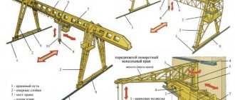
Magnetic grab overhead cranes
They are sold with one, two or four ropes on which multi-jaw magnets are attached. Magnets are used:
- for loading scrap metal round;
- for loading rails are rectangular.
These devices are hung on a hook, which can be used as a stand-alone device. The bridge beams are produced using a robotic submerged arc welding method. For the production of structural elements, ST3 or 09g2s steel is used.
Overhead magnetic grab cranes are used in scrap processing shops and are also widely used in charge departments of metallurgical plants.
Circuit with two time relays
The second scheme, which seems to me the simplest and most understandable and which I have often encountered in practice, differs from the previous one in that the time of supply of the demagnetizing current to the magnet winding is regulated by two REV relays. When the controller contact is closed, contactors B1, B2 and relay RV (REV type) are turned on. As is known, the contacts of the REV relay are activated when power is supplied to its coil without delay, and when the power supply is interrupted, they return to their original state with a delay. Therefore, the contacts of the above two contactors and the relay operate simultaneously, and immediately when block contact 1B is closed, the RP relay (also of the REV type) is turned on. The RP contact closes (there is only one), but this does not lead to the operation of H1 and H2, since the normally closed contact RB is open.
The crane operator opens controller K. Contacts B1 open, and here the REV relay comes into play. The radio is configured for a short delay, as they say, about 0.2 seconds. After this time, its normally closed contact closes, and since the RP is configured for a much longer delay (about 2 seconds), the power supply circuit H1 and H2 is closed. A demagnetizing current begins to flow through the electromagnet coil, which continues until the RP contact opens.
Advantages
All products have a lot of advantages:
- long period of operation with a 20-year warranty;
- high level of security;
- possibility of installing manual or radio control;
- excellent productivity at work;
- quick access to all components, interchangeability of parts;
- high quality materials and workmanship.
Overhead cranes are certified in accordance with TR CU 010/2011 “On the safety of machinery and equipment”. When designing a crane, we take into account the operating temperature, work intensity and other factors that affect the crane’s performance. We will advise you on the details and install it on site.