As you know, trucks use an electrical equipment system where current consumers are connected to sources with only a single wire (the other wire goes to ground).
The electrical wiring of the GAZ 53 is no exception in this regard. In this article we will find out what the main differences of this circuit are and trace the power circuits of the main current consumers.
Electrical diagram
Electrical diagram of GAZ 53-12
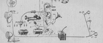
A detailed diagram of the electrical connections of the GAZ 53 is shown in the figure below (click to enlarge).
Electrical diagram of the GAZ 53-12 car
- side turn signal
- front light
- headlight
- connection panel
- high beam thread
- low beam thread
- turn signal lamp
- side light lamp
- gasoline solenoid valve
- solenoid gas valve
- starter
- interference suppression tip
- candles
- distributor sensor
- generator
- sound signal
- PETROL-GAS switch
- accumulator battery
- ignition coil
- transistor switch
- fuse
- voltage regulator
- fan motor
- horn button
- connection panel
- heater motor
- additional resistor
- additional starter relay
- gas pressure sensor
- resistor
- heater switch
- engine compartment lamp
- switch
- starting heater control panel
- control resistor
- candle
- spark plug switch
- solenoid valve
- oil pressure sensor
- engine temperature sensor
- engine overheat sensor
- emergency oil pressure sensor
- fuse
- foot light switch
- hazard switch
- ignition switch
- gas pressure indicator
- brake warning light
- current indicator
- fuel level indicator
- oil pressure indicator
- engine temperature gauge
- engine overheating indicator
- oil pressure indicator
- fuel sensor switch
- trailer turn signal indicator
- turn signal indicator
- instrument lamp
- high beam indicator
- light switch
- turn signal switch
- turn signal and hazard warning relay
- wiper motor
- wiper switch
- portable lamp socket
- fuse 15 A
- main tank fuel level sensor
- fuse 20 A
- lampshade
- lamp switch
- auxiliary tank fuel level sensor
- brake warning light test switch
- brake light switch
- brake warning light sensor
- turn signal lamp
- side light lamp
- brake light
- trailer socket
- back light
Wire color designation on the GAZ 53 electrical diagram:
- B - white
- K - red
- F - yellow
- Z - green
- Kch - brown
- H - black
- G - blue
- O - orange
- P - pink
- F - purple
- C - gray
Description
Connection of turn relay 3 contacts
The electrical circuit of the GAZ-3307 is a drawing on which there are pictograms of the electrical elements of the car, connected to each other by switching lines indicating wires. The equipment is located approximately where it is when looking at the machine from above, although deviations (sometimes significant) are possible. On the left are usually the headlights and sidelights of the front of the car, to the right are the electrical equipment of the engine compartment, interior and rear lights.
Electrical circuits are available in black and white and color. The latter are easier to read; the colors of the lines are the same as those of the corresponding wires. Often electrical components are shown in the form of pictures (instrument panel, starter, headlights, etc.), they can be recognized without looking at the “legend” (the explanatory text under the diagram or on the side of it). An example of a color wiring diagram is shown below.
Black and white diagrams are usually more detailed and often provide additional information (for example, thin lines show current conductors inside devices). The color of the wires is indicated by a letter (H - black, Z - green, and so on). The numbers (2; 0.5 and others) in the breaks in the switching lines indicate the cross-sectional area of the wire in square millimeters.
There are standard pictograms and conventional images of certain devices. Next to them (sometimes on a callout) is a number or letter with numbers. This is the designation of the element whose name is indicated in the “legend”.
How to set the ignition to gas 53 Video
Gas66 electronic ignition system diagram.
diagram of the gas ignition system 66 How to install gas on the ignition 53 Video
Full line: GAZ-3307, 53, GAZ-3309, GAZ-66, 3308, 33081, 33086, GAZ-33104
Ignition installation for GAZ-53, GAZ-3307 cars
The ignition system of GAZ-53, GAZ-3307 is a 12-volt contactless battery transistor, consisting of electronic current sources, an ignition coil, an additional resistor, a switch, an ignition switch, spark plugs, spark plugs, an ignition switch and a low ignition voltage.
Rice. 1. Diagram of the ignition system GAZ-53, GAZ-3307
A - to the starter; 1 - ignition coil; 2.7 - primary winding; 3 - secondary winding; 4 - battery; 5 — current indicator; 6 - additional starter relay; 7 - additional resistor; 8 — ignition switch and starter; 9 - noise reduction resistor; 10 — spark plug; 11 — distributor sensor; 12 — resistor slider for noise suppression; 13 — distributor winding; 14 - permanent magnet; 15 - switch; R1 - MLT-8.2 kOhm resistor; R2 - MLT-1 resistor, R3 - MLT resistor; R4 - MLT-82 kOhm resistor; R5 - MLT-62 Ohm resistor; R6 - MLT-200 Ohm resistor; R7, R8 - MLT-47 kOhm resistors; C2 - capacitor K73-17-250B-0D; SZ - capacitor K73-17-4008-1; Capacitors C4, C5 - K73-17-250V-0.047 µF; C6 - capacitor K50-29-160V-10; C7 - capacitor KL-2-I20-500V-1000; VI - KDYu2BiliKD4 521A; V2 - diodes KD209A or KD212A; V3 - CT 848 A transistor; V4, V5 - KT630B transistors, also known as KT653B; V7 is a 102V diode
Reliable and economical engine operation depends on the uninterrupted operation of the GAZ-53 ignition system. To eliminate radio interference caused by the ignition system, the high voltage wires have a distributed resistance and the spark plug tips have suppression resistors. A diagram of a set of ignition accounting programs is shown in Fig. 1.
Technical characteristics of the ignition system of GAZ-53, GAZ-3307 cars
Ignition order for GAZ-53. 1 - 5 - 4. 2-6 - 3.7 - 8 Type of ignition distributor. 24.3706 Camshaft rotation speed is 1 min with continuous ignition during operation with B116 ignition coil on a three-electrode spark gap with a 7 mm spark gap, min-1. 20 - 2300 Direction of rotation of the distributor (distributor) of the GAZ-53 roller. clockwise Ignition coil GAZ-53. B116 Candles. A11 Spark gap size in spark plugs, mm 0.8 - 0.95 Additional resistor. 14.3729 Switch. 13.3734 or 13.3734-01 Spark plug tip 35.3707200 Tip resistance, kOhm. 4 - 7
The ignition coil GAZ-53, GAZ-3307 (V 116) is used to convert low voltage current into high voltage current.
The ignition coil GAZ-53, GAZ-3307 (B 116) is a transformer, on the metal core of which a secondary element is wound, and above it is a primary winding. The core with windings is installed in a sealed iron case, filled with oil and covered with a high-voltage plastic case.
Winding resistance at 15 - 35 ° C: primary 0.43 Ohm, secondary 13,000 - 13,400 Ohm.
Maintenance of ignition GAZ-53, GAZ-3307
To protect against possible damage to the plastic cover, the coil must be cleaned of dirt, dust and oil to check the reliability of the high and low voltage wires.
When the engine is not running, you cannot leave the ignition on to avoid the coil overheating, causing it to malfunction. The use of other types of ignition coils is not permitted.
The causes of malfunction of the ignition coil of GAZ-53, GAZ-3307 are: broken insulation; intercircuit diagram; chips and cracks in the plastic cover; burnout of the ignition coil due to the absence of a high-voltage wire in the socket.
In the windings of the ignition coils, deficiencies in most cases arise due to their overheating and operation with enlarged spark gaps. Overheating occurs mainly when the ignition is turned on and the engine does not start.
When removing the GAZ-53, GAZ-3307 ignition coil for replacement, make sure that the wires are connected to the coil terminals in good condition and securely fastened. The coil must be tested on a special screen with a transistor switch, an additional resistor and a distributor.
Main technical characteristics
The G287 generator on the GAZ-66 has an output power of 1260 W, which is sufficient for the simultaneous operation of all the electrical equipment of the truck.
Its factory characteristics:
- Characteristic name Indicator
- Type three-phase, synchronous, alternating current
- Movement of the rotary mechanism to the right of the pulley
- Maximum voltage, V 14
- Limit electric current, A 90
- Rotation speed providing
- terminal voltage 14 V (with
- ambient temperature + 20
- degrees C) when the electric current is 0 A /
- 60 A, rpm 850 / 1800
GAZ 66 generator circuit
- Number of stator phase moments, pcs. 3
- Number of coil modules in phase
- moment 6
- The number of revolutions in the reel
- mechanism 16
- Wiring of the stator winding, type PEV2 or PEV200 1.40–1.56 mm in diameter
- Winding wiring on the excitation coil,
- type PEV2 0.93 mm in diameter
- Number of revolutions in the coil, pcs. 520 +/- 10
- Winding resistance indicator
- excitation at +25 degrees C, Ohm 3.2 + / - 0.2
- Brush type M1
- Spring stiffness, gf 180–260
- Front cover bearing type 6-1180304К1С9Ш1
- Rear cover bearing type 6-180603KS9Sh1
- Rectifier module, type BPV7-100
- Number of diodes 12
Possible wiring faults
Ignition coil connection diagram
If electrical equipment stops working, you need to check the wiring.
It is characterized by several malfunctions:
- A broken wire is often a consequence of its installation in an unreliable place. When laying wires, you need to take into account that they should not come into contact with moving parts.
- Leakage current. Usually such a malfunction occurs due to a breakdown in the wire. In order to prevent such a problem, all wiring must be reliably insulated.
- Poor contact. As a rule, this failure is associated either with oxidation of the contact or with disconnection of the cable from the equipment due to poor fixation or vibrations.
Remove the oil pan.
To remove the oil pan. The engine must be turned upside down. To do this, you need to prepare wooden blocks. The size of the bars is chosen based on the consideration. So that they pass between the studs. And they were higher than stilettos. ,Because when the block turns over. The pins should not touch the table surface. Otherwise, the threads on the studs will be damaged. When the engine is positioned with the sump facing up, you can unscrew the nuts securing the sump. There are many of them. The pallet sticks to the gasket, the pins cling to it, and again difficulty arises with removal. Here you can pry up the pallet itself. Or you can place a wooden block and hit it from the side to the bottom area. On one side and on the other. And the pallet will come away. When the pan is removed, the oil receiver must be removed. The bracket from the main cover and the nut at the base of the oil receiver are unscrewed.
Model history and purpose
Ignition and wiring diagram for an 8 valve VAZ-2114
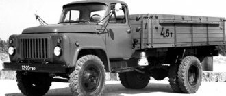
GAZ 3307 is a popular Russian truck, produced by the Gorky Automobile Plant. Production of the car began in 1989 and continues to this day. The model started very successfully, but quickly lost popularity. After the collapse of the USSR, the car noticeably lost in demand, and its large-scale production ceased. GAZ 3307 was seriously inferior to competitors of that time and was soon replaced by a more advanced model - GAZ 3309. However, the production of the truck did not stop completely. The Gorky Automobile Plant continues to supply special versions for government agencies (single orders). Carburetor GAZ 3307 is also exported to the Belarusian market.
GAZ 3307 is the successor to the GAZ 53, popular in the USSR. By the end of the 1980s, this truck was seriously outdated and needed updating. This was the impetus for the creation of a fundamentally new model. The car was designed to work on paved roads. GAZ 3307 belongs to the fourth generation of products from the Gorky Automobile Plant. It also includes GAZ 3309, GAZ 3306 and GAZ 4301 cars.
One of the priorities when creating the model was considered to be large-scale unification of the main elements and components with its predecessor. As a result, the model received many of the parts of the GAZ 53. Such a solution made it easier to maintain the car and reduced costs. At the same time, the GAZ 3307 surpassed the GAZ 53 in many characteristics. The hood layout of the truck has been preserved. The main difference of the car was the improved cabin and new tail. There is more space in the cabin, ventilation and heating have been added. Minor changes also affected the power plants.
At the Gorky Automobile Plant, the GAZ 3307 was positioned as a transitional option, which in the future was to be replaced by diesel versions with increased efficiency. The company soon began producing diesel engines itself.
Production of the carburetor version of the GAZ 3307 finally ended in the early 1990s. Diesel versions also lost popularity every year, so their production soon became unprofitable. Now the plant offers exclusively gasoline modifications of the truck (produced to order only). The basis of GAZ 3307 is used to create special-purpose vehicles. At the same time, the design of the trailer allows for the transportation of bulky and heavy loads.
The GAZ 3307, despite its large dimensions, is a very maneuverable vehicle, so moving through city traffic is quite easy. The model also feels good off-road.
The car can be operated in any climatic conditions, which is especially important for Russia. Endurance is the main advantage of the model
The main purpose of the GAZ 3307 is the transportation of various cargoes. The large availability of add-ons allows you to select the equipment necessary for specific tasks. On the basis of the model, aerial platforms, milk tankers, truck cranes and garbage trucks are made, which significantly expands the scope of application of the vehicle (general cargo transportation, construction industry, public utilities, national economy).
Existing insertion methods
For each car model, appropriate gas equipment is selected. Inserting an LPG into a second-generation carburetor is no different from the first LPG. The master selects the best option individually, taking into account the design of the machine.
The simplest option is to install a spacer mixer equipped with a separator. Inserting gas into the carburetor in this way has the main advantages:
- the carburetor body is not subject to mechanical stress;
- there is no drilling process.
This option is often used for inserting gas fittings in carburetors, such as “Ozone”. To do this, remove the textolite gasket and install a gas mixer. This technological operation can be performed on any conventional carburetor.
The installed gas mixer is equipped with a power register. The design provides two outputs, with the possibility of autonomous adjustment. Thanks to the register, you can set the optimal gas supply. This allows you to significantly reduce gas consumption and obtain the best dynamic characteristics. Simple installation has made this method highly popular.
Electrical diagram of GAZ 53
The GAZ 53 truck was designed and produced in the Soviet Union, and the automotive equipment in the country at that time was not distinguished by its complexity and the presence of additional options. At that time there were no air conditioners or electric windows, although some cars could have a pre-heater installed. But in the national economy this was more a vital necessity than an element of tuning.
GAZ 53 truck with extended sides
But repairing a GAZ-53 should not be difficult, because the time and labor that you will spend on it will not take much effort from you. Everything can be complicated by the fact that in order to repair various elements, parts, equipment, and so on, when you tinker with the car yourself, you need to have a diagram of these elements. Only they are not there, and the instruction manual has long been lost, because the GAZ-53 has not been produced for 20 years.
Replacement
The GAZ 53 generator is located in the front upper part of the engine, in the area of the intake manifold next to the valve cover of the 4th-8th cylinder. Replacing the part is very simple - it is easy to reach, and at the same time it has a minimum of fasteners. To remove you need:
- Disconnect the electrical circuit of the car (disconnect the terminals from the battery);
- Remove all wires from the generator;
- Unscrew the bolt securing the tension bar and turn the generator to release the belt;
- Remove the belt, unscrew the bolts and nuts of the lower fastening (only two bolts and nuts) and dismantle the generator;
- Install the new generator by performing all steps in reverse order.
How to Correctly Install the Ignition on Gas 53
How to properly install the ignition on gas 53
Ignition installation for GAZ-53, GAZ-3307 cars
The ignition system of GAZ-53, GAZ-3307 is a 12-volt contactless battery transistor, consisting of electronic current sources, an ignition coil, an additional resistor, a switch, an ignition switch, spark plugs, spark plugs, an ignition switch and a low ignition voltage.
Rice. 1. Diagram of the ignition accounting system for GAZ-53, GAZ-3307
A - to the starter; 1 - ignition coil; 4 - primary winding; 3 - secondary winding; 4 - battery; 5 — current indicator; 6 - additional starter relay; 7 - additional resistor; 8 — ignition switch and starter; 9 - noise reduction resistor; 10 — spark plug; 11 — distributor sensor; 12 — resistor slider for noise suppression; 13 — distributor winding; 14 - permanent magnet; 15 - switch; R1 - MLT-8.2 kOhm resistor; R2 - MLT-1 resistor, R3 - MLT resistor; R4 - MLT-82 kOhm resistor; R5 - MLT-62 Ohm resistor; R6 - MLT-200 Ohm resistor; R7, R8 - MLT-47 kOhm resistors; C2 - capacitor K73-17-250B-0D; SZ - capacitor K73-17-4008-1; Capacitors C4, C5 - K73-17-250V-0.047 µF; C6 - capacitor K50-29-160V-10; C7 - capacitor KL-2-I20-500V-1000; VI - KDYu2BiliKD4 521A; V2 - diodes KD209A or KD212A; V3 - CT 848 A transistor; Transistors V4, V5 - KT630B or KT653B; V7 is a 102V diode
Reliable and economical engine operation depends on the uninterrupted operation of the GAZ-53 ignition accounting system (software). To eliminate radio interference caused by the ignition system, the high voltage wires have a distributed resistance and the spark plug tips have suppression resistors. The circuit allows you to keep track (software) of the ignition, shown in Fig. 1.
Technical feature of the ignition accounting system for GAZ-53, GAZ-3307 cars
Ignition order for GAZ-53. 1 - 5 - 4. 2-6 - 3.7 - 8 Type of ignition distributor. 24.3706 Camshaft rotation speed is 1 min with continuous ignition during operation with B116 ignition coil on a three-electrode spark gap with a 7 mm spark gap, min-1. 20 - 2300 Direction of rotation of the distributor (distributor) of the GAZ-53 roller. clockwise Ignition coil GAZ-53. B116 Candles. A11 Spark gap size in spark plugs, mm 0.8 - 0.95 Additional resistor. 14.3729 Switch. 13.3734 or 13.3734-01 Spark plug tip 35.3707200 Tip resistance, kOhm. 4 - 7
The ignition coil GAZ-53, GAZ-3307 (V 116) is used to convert low voltage current into high voltage current.
The ignition coil GAZ-53, GAZ-3307 (B 116) is a transformer, on the metal core of which a secondary element is wound, and above it is a primary winding. The core with windings is installed in a sealed iron case, filled with oil and covered with a high-voltage plastic case.
Winding resistance at 15 - 35 ° C: primary 0.43 Ohm, secondary 13,000 - 13,400 Ohm.
Technical ignition service for GAZ-53, GAZ-3307
To protect against possible damage to the plastic cover, the coil must be cleaned of dirt, dust and oil to check the reliability of the high and low voltage wires.
When the engine is idling, you cannot leave the ignition on when the coil overheats, which will cause it to malfunction. The use of other types of ignition coils is not permitted.
The reasons for the failure of the ignition coil of GAZ-53, GAZ-3307 will be: broken insulation; intercircuit diagram; chips and cracks in the plastic cover; burnout of the ignition coil due to the absence of a high-voltage wire in the socket.
In the windings of the ignition coils, deficiencies in most cases arise due to their overheating and operation with enlarged spark gaps. Overheating occurs mainly when the ignition is turned on and the engine does not start.
Before removing the ignition coil of GAZ-53, GAZ-3307 for replacement, you must make sure that the wires are connected to the coil terminals in proper and reliable condition. The coil must be tested on a special screen with a transistor switch, an additional resistor and a distributor.
Main technical characteristics
Generator circuits with excitation from the generator output - circuits without additional diodes
The G287 generator on the GAZ-66 has an output power of 1260 W, which is sufficient for the simultaneous operation of all the electrical equipment of the truck.
Its factory characteristics:
- Characteristic name Indicator
- Type three-phase, synchronous, alternating current
- Movement of the rotary mechanism to the right of the pulley
- Maximum voltage, V 14
- Limit electric current, A 90
- Rotation speed providing
- terminal voltage 14 V (with
- ambient temperature + 20
- degrees C) when the electric current is 0 A /
- 60 A, rpm 850 / 1800
GAZ 66 generator circuit
- Number of stator phase moments, pcs. 3
- Number of coil modules in phase
- moment 6
- The number of revolutions in the reel
- mechanism 16
- Wiring of the stator winding, type PEV2 or PEV200 1.40–1.56 mm in diameter
- Winding wiring on the excitation coil,
- type PEV2 0.93 mm in diameter
- Number of revolutions in the coil, pcs. 520 +/- 10
- Winding resistance indicator
- excitation at +25 degrees C, Ohm 3.2 + / - 0.2
- Brush type M1
- Spring stiffness, gf 180–260
- Front cover bearing type 6-1180304К1С9Ш1
- Rear cover bearing type 6-180603KS9Sh1
- Rectifier module, type BPV7-100
- Number of diodes 12
Connection diagram for generator 5101.3701 on GAZ 3309, 28 Volt cars
Can I install another generator?
Yes, you can install the G 273V1 Kamazovsky, but you need to adapt the pulley.
A pulley from the Valdai generator will fit on it
Generator 5101.3701 is made according to a circuit with additional diodes. Voltage regulator Ya120M12. Old-style figure-eight diode bridge BPV 56-65-02 with two wires.
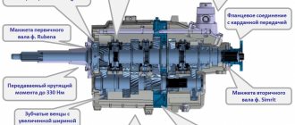
The generator consists of a housing, stator winding, rotor, diode bridge and built-in voltage regulator.
The housing and main parts are similar to the KZATE 372.3701 generator for eight, however:
The stator winding is designed for 28 Volts and will not work from a figure-eight generator.
The generator rotor is designed for 28 Volts and will not work with a figure-eight generator.
The peculiarity of this type of generator is that a cap is made at the rear of the generator, in which a voltage regulator is mounted. This design improves the splash protection required for SUVs. When repairing such generators, it becomes difficult to arrange the wires connecting the voltage regulator and the generator. How to arrange the wires correctly?
Purpose of the voltage regulator. 28 Volt voltage regulator YA120M12 and its analogues
Main components of the design
How to read car electrical diagrams? How to read electrical circuit diagrams correctly?
On the GAZ-66, the generator is located on the right side of the engine and is attached directly to the car body using a bracket.
Its main elements:
- Name of component Functional purpose
- Rotor group consisting of a winding shaft
- excitation and welded on the outside
- surfaces of beak-shaped stripes in
- quantity of 12 pieces. Responsible for creating a magnetic field during rotation and is located inside the device. Rotation is ensured by two belts combined with the engine crankshaft pulley
- Stator group, including steel package
- plates, winding in the form of connected
- groups of coils Induces an electric current on the stator winding
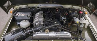
This is what the GAZ 66 engine looks like
- Closing module with pre-installed
- bearings Ensure the tightness of the housing, as well as the rotational movements of the rotor component
- Module with brushes Redirects the electric current produced by the generator into the vehicle's electrical network
- Rectifier block (diode bridge) Provides rectification of incoming alternating current
- Voltage control module (regulator) Responsible for changing and controlling the current generated in the stator phase windings
Fuses and relays
In the vehicle electrical system, thermobimetallic fuses of two types are used: with a return button and continuous action. Thermobimetallic fuses with a return button are located on the lower flange of the instrument panel to the left and right of the steering column.
Fuses protect the following circuits:
- left type PR315 for 15 A - instrument circuits, heater electric motor, direction indicators and sound signal.
- right type PR2-B for 20 A - lighting circuits.
- A PR2-B fuse is installed on the preheater control panel, which protects the heater circuits.
Thermobimetallic fuse device with a return button
Designation
- conclusion;
- frame;
- bimetallic plate;
- return button;
- contact;
- screw;
- central adjustment screw;
- screw.
To turn on the fuse, there is a return button 4, when pressed, the bimetallic plate will take its original position, the contacts will close again, and the current in the circuit will be restored.
Thermobimetallic continuous fuse for a car
GAZ-53-12
The fuse serves to protect the wiper motor from overloads and short circuits.
The bimetallic plate is fixed at one end to one terminal, and at the other end it has a contact that connects to a contact installed on the second terminal. The current to the electric motor passes through the bimetallic strip.
Let's take a closer look at the design and operation of turn signal lights:
The most widely used are turn signal indicators with an electromagnetic-thermal current interrupter - RS57, RS57-V, designed for 12 V, and RS401 - for 21 V.
Turn signal device. A winding consisting of 50 turns of PEL wire with a diameter of 0.75 mm is placed on the steel core 9 (Fig. 3). The core is rigidly connected to bracket 11. The breaker winding is connected in series with warning lamps 16 or 17 located in the rear light and sidelight, and when using PC57 V, with warning lamp 12 located on the instrument panel in the driver's cabin. Steel anchors 4 and 10 are welded to the core
In the non-working state, contacts 5 are opened by the force of the stretched nichrome string 3, and contacts 6 are opened by the tension of the bronze plate 8. All contacts of the breaker are silver.
The lower end of string 3 passes through glass bead 2 and is thickened by fusing solder. The bead insulates the string from the bracket.
The resistor has a resistance value of 18 Ohms, made of nichrome conductor.
Normal operation of the RS57 breaker is ensured by simultaneously turning on two signal lamps of 21 light, and the RS57-B of two signal lamps of 32 light and one control lamp of 1 light. If one of the signal lamps burns out, the current strength decreases, as a result of which the blinking frequency of the lamps significantly increases, and in the circuit with the PC57 relay, the control lamp does not turn on.
Turn signal operation. When the signal lamps are turned on, the current from the battery will pass through the ignition switch 13, armature 4, string 3, resistor, winding, switch 15 and to the lamps (see Fig. 3). The current path in the diagram is indicated by arrows. The filament heat will be small.
GAZ 3307 wiring diagram: features of the transition model
The fourth generation of the GAZ 3307 medium-tonnage truck was born in 1993 and completely replaced its predecessor, the GAZ 52/53, on the assembly line. As has been customary all these years, the car was largely unified with its platform, but it also had some differences that made it more modern.
The factory manual contains a color diagram of electrical equipment
Features of GAZ 3307
This model was considered a transitional model, so the automaker did not consider it as an object for serious modification. The following was inherited from its predecessor:
- Chassis;
- Power unit;
- Body, including its cargo modifications;
- Basic controls.
New cabin
A new element of the GAZ 3307 car was a modern cabin. She was different:
- Angular tail of the hood and wings;
- New lighting technology;
- Interior decoration;
- Adjustable seats with seat belts.
Original photo of the new dashboard
In addition, thanks to the installation of a new cabin with increased functionality on the chassis, the electrical wiring of the GAZ 3307 was also modified. This was required by the appearance on the car:
- Efficient ventilation and heating systems;
- Power steering;
- New instrument panel.
Electrical equipment
As for the electrical equipment, in connection with the manufacturer’s experiments trying to select the optimal power unit, the engine compartment wiring of the GAZ 3307 also underwent modernization.
In particular:
- Instead of the previously used DC generator, the car received an alternating current generator model G250-G2;
- To protect the electrical equipment, a voltage regulator model 222.3702 was integrated.
GAZ 3307 wiring diagram: generator and voltage regulator switching circuit
Caution: Do not start the engine if the cable from the generator to the regulator is damaged, as well as checking for a spark. The electrical circuit is not designed for such loads, so it will fail during any attempt to start or test.
The ignition system has also undergone a slight modernization:
- Instead of the old B114-B ignition coil, a more powerful B116 was installed;
- The old distributor R133-B was replaced with a modernized 24.3706;
- An electronic ignition switch model TK102A appeared. Later, instead of it, the car was equipped with a universal switch 13.3734, as well as its modification - 13.3734-01;
- The circuit uses a resistor SE107, and on a number of models the universal 14.3729 was installed (see also the Gazelle wiring diagram).
The GAZ 3307 ignition system is quite accessible for do-it-yourself maintenance
Verification methods
Given the external similarity of the electrical equipment, the automaker reasonably assumed the possibility of errors when servicing the car independently, the price of which was high. Therefore, I provided automatic protection of elements from accidental short circuits:
- The generator excitation winding circuit is protected using a protection relay, as well as a separating diode;
- While the engine and generator are running, the relay contacts are open;
- If a wire breaks or short circuits, the current flowing through the relay winding will increase;
- The opposing winding will create a magnetic field, the core will retract and open the relay contacts (see also the VAZ 2101 wiring diagram).
Contact-transistor protection circuit
To check the serviceability of the protection you must:
- Turn off the engine;
- Turn on the ignition;
- Connect the voltage of the relay-regulator to ground;
- Alternately press the anchors RN and P3, closing their contacts.
If the relay is working properly, the voltmeter needle will move to the “0” mark. If this does not happen, the transistor is faulty and the relay regulator must be replaced.
conclusions
We hope that in this material we were able to provide a detailed explanation of the features of the car. And the video in this article and detailed electrical diagrams will allow GAZ 3307 owners to independently detect faults in electrical circuits and restore their operating parameters (see also GAZ 3110 wiring diagram).
Disassembling the generator
We disassemble the device as follows:
Unscrew the pulley mounting nut and remove the pulley
You should pay attention to the key - it is better to immediately remove it and put it in a safe place so as not to lose it; Unscrew the two screws securing the brush assembly and dismantle the assembly; Unscrew the three screws of the rear plug; We unscrew the long tightening screws on the rear cover of the generator; they tighten both parts of the housing together. Remove the back cover and disconnect the wires on the cover near the diode bridge.
The fourth generation of the GAZ 3307 medium-tonnage truck was born in 1993 and completely replaced its predecessor, the GAZ 52/53, on the assembly line. As has been customary all these years, the car was largely unified with its platform, but it also had some differences that made it more modern.
Design of the GAZ 53 ignition system
The GAZ-53 is equipped with a non-contact transistor ignition system, the primary circuit of which produces a voltage of 12 volts. The ignition system is considered battery-based, consisting of sources of electric current, which can be a battery, ignition coil, switch, sensor-distributor, and other electrical equipment gas 53, which most often causes problems, since it needs to be adjusted, spark plugs with tips, additional resistor, ignition switch, low and high voltage wires.
The drawing shows a complete diagram of the GAZ-53 ignition system
The ignition system is one of the most important systems in a car, since the operation of the engine, as well as the fuel consumption of the entire car, depends on its proper operation. To suppress radio interference created by high voltage wires and spark plug tips, distributed resistance is installed on the former, and suppression resistors are installed on the latter.
The ignition system contains a B 116 brand coil, the purpose of which is to convert low voltage current to high voltage.
In turn, the coil consists of a transformer in which an iron core is mounted. The primary winding is wound on top of this core, and the secondary winding is below it. The transformer itself is a steel case, which is hermetically sealed; oil is poured inside it along with the core.
To maintain this transformer, a plastic cover is provided that can withstand high voltage.
The first GAZ 53 trucks had a contact-transistor ignition system, then it became contactless electronic. Since the contact (or contact-transistor) system is already hopelessly outdated, we will consider a contactless system. The GAZ 53 ignition system consists of a low-voltage and high-voltage circuit. The low voltage circuit includes:
- Accumulator battery. In the battery, six 2-volt banks are connected in parallel to each other, for a total of 12 volts. The GAZ 53 is equipped with a 6ST-75 battery with a capacity of 75 a/h as standard.
- Battery wires with terminals. The wires are multi-core and have a large cross-section.
- Egnition lock. Serves to supply power to the low-voltage circuit. In the extreme left position (clockwise), the contacts on the starter solenoid relay are closed, and the engine is driven by the starter.
- Breaker. In GAZ 53 it is located in the distributor. In contact ignition, the role of the breaker was performed by the cam shaft of the distributor and the ignition contacts; in a more modern version, the role of the breaker is performed by the Hall sensor.
- Switch. Ensures stable operation of the breaker.
- Variator (resistance). Provides stable engine starting and relieves the work of the ignition coil at high engine speeds. Due to the variator, the coil does not overheat. On more modern versions of the system, the variator was removed (in the gas 3307 model), and the role of the variator began to be played by an additional transistor located in the circuit of the new switch.
- Primary winding of the ignition coil (SC). It has a small number of turns and relatively thick copper wire.
Checking the ignition coil with a multimeter
The secondary (high-voltage) circuit contains the following elements:
- Secondary winding short circuit. It has a large number of turns and thin copper wire.
- Ignition distributor GAZ 53. The distribution part of the distributor consists of a shaft, a distributor cap and a slider.
- High voltage wires and lugs. Through them, a high-voltage pulse is supplied to the spark plugs.
- Spark plug.
Main components of the design
On the GAZ-66, the generator is located on the right side of the engine and is attached directly to the car body using a bracket.
Its main elements:
- Name of component Functional purpose
- Rotor group consisting of a winding shaft
- excitation and welded on the outside
- surfaces of beak-shaped stripes in
- quantity of 12 pieces. Responsible for creating a magnetic field during rotation and is located inside the device. Rotation is ensured by two belts combined with the engine crankshaft pulley
- Stator group, including steel package
- plates, winding in the form of connected
- groups of coils Induces an electric current on the stator winding
This is what the GAZ 66 engine looks like
- Closing module with pre-installed
- bearings Ensure the tightness of the housing, as well as the rotational movements of the rotor component
- Module with brushes Redirects the electric current produced by the generator into the vehicle's electrical network
- Rectifier block (diode bridge) Provides rectification of incoming alternating current
- Voltage control module (regulator) Responsible for changing and controlling the current generated in the stator phase windings
Electrical diagram
First of all, we note that any electrical circuit of a car, including one like the GAZ 53, is equipped with the following elements:
- GPT – alternating current generator;
- KTS – contact-transistor ignition system;
- start heater;
- wiring of different voltages connecting all elements into a single circuit.
Attention. The electrical circuit of the GAZ-53 truck is not designed for non-standard loads
Therefore, it is forbidden to start the engine if the cable running from the generator to the regulator is damaged or if it “sparks”.
Ignition system
Let's first consider the ignition system. It is known that it is battery operated, with a circuit voltage of 12 V.
It also consists of the following components:
- switch;
- sources supplying current;
- coils;
- resistor (additional);
- ignition distributor (distributor);
- candles with their tips;
- ignition switch;
- wiring.
Note that the smooth operation of the engine directly depends on the normal functioning of the ignition system. To avoid radio interference caused by the ignition system, the wires are equipped with a resistance distributor (this mainly applies to HV wires), and the tips of the spark plugs are equipped with suppression resistors. (See also the article Features of the GAZ wiring diagram.)
Let us now consider each element of the ignition system separately and find out how it functions.
Spark plugs for GAZ 53 must have a factory gap of 0.85 mm. They must have a nichrome electrode - A11, A11-1, A10-H and others are suitable. The ignition order can be seen in the photo below.
- The ignition distributor is used in this car so that the rotation speed of its roller is one minute with uninterrupted sparking. Functions simultaneously with the ignition coil. The roller must rotate clockwise.
- Ignition coil - B114-B or B116 (more advanced). Generates high voltage pulses in the ignition system of a GAZ 53 car. It has a rated voltage of 12V and a secondary voltage of 17kV.
- The ignition switch amplifies the signal from the distributor sensor and the ignition coil. (See also the article Gazelle wiring diagram: how to install it yourself.)
Note. To connect all of the above parts and assemblies of the vehicle's electrical equipment into a single circuit, low voltage wires are used. They must be protected with polyvinyl chloride insulation.
Removing the crankshaft
Schematic diagram of the electrical equipment of a car
The front cover has already been removed. Now you should unscrew the cover of the stuffing box. It is secured with two nuts with internal edges for an 8 mm hexagon. After removing the nuts, remove the cover. It will go hard because it is spread out by rubber seals on the sides. Keep in mind. After this, you need to make your marks on the covers. The reason is the same: factory numbers are hard to read. And therefore the lids can be confused. A cover placed in the wrong place will lead to jamming of the shaft. You should also mark in front along the direction of the engine. On one side of the cover in order. This will help you check your work later during assembly. Remove the crankshaft covers. And we pull out the crankshaft. It needs to be disassembled.