The domestic automobile industry dates back to May 31, 1929, when the Soviet government signed a contact with Ford Motor Company for technical assistance in organizing production. And every time our engineers had to show ingenuity, be it the launch of the first NAZ-AA model or the GAZ 52 electrical wiring diagram being developed.
Schematic diagram of the electrical equipment of the GAZ M1 model 1939
For reference: At the end of January 1932, the first domestic cars rolled off the factory assembly line in Nizhny Novgorod. They received the name NAZ-AA, which stood for Novgorod Automobile Plant and the first AA model. After 8 months, Nizhny Novgorod was renamed Gorky, according to the order of the USSR Government. And from that moment on, the plant’s abbreviation in the names of vehicles also changed from NAZ to GAZ.
Search for problems with wiring GAZ-53 and 52, color wiring diagram with description
Features of electrical equipment
To begin with, we suggest that you familiarize yourself with the description of the main components of the electrical circuit:
- Ignition system. It includes a switchgear, coil, commutator, spark plugs, and high-voltage wires. These wires transmit a spark to ignite the combustible mixture.
- A starter, without which starting the engine will also be impossible.
- A generating device that supplies power to the main equipment while driving.
- Optics. We are talking about headlights, brake lights, parking lights, as well as light alarms or turn signals.
- Electric motor of the heating system.
- Electric motor for windshield cleaning system.
- The instrument panel contains the main sensors, including fuel level and engine temperature.
- Steering column switching system - allows you to activate the windshield wipers, as well as turn on the turn signals (video author - Andrey Nabokov).
How to determine the malfunction?
You can determine the malfunction in the electrical wiring either yourself or with the help of a specialist.
There are only two vehicle states in which the equipment may not work:
- The car won't start or drive. In this case, first of all, you should diagnose the battery, starter, ignition switch, distributor, spark plugs. As a rule, the problem lies precisely in the spark plugs or battery; the problem of high-voltage wires is diagnosed much less often.
- The car starts and drives, but the electrical equipment does not work. If we are talking about optical lamps, then perhaps the problem lies in their burnout or failure of the fuse. If a group of devices refuses to work, for example, turn signals and wipers, then it makes sense to check the functionality of the steering switch. If there are problems with the operation of certain devices, but you are sure that the devices themselves and the fuses responsible for their operation are working, then you need to check the wiring. You will need a multimeter or an electrician to do this.
Diagnostics of battery charge with a multimeter
Possible wiring faults
If electrical equipment stops working, you need to check the wiring.
It is characterized by several malfunctions:
- A broken wire is often a consequence of its installation in an unreliable place. When laying wires, you need to take into account that they should not come into contact with moving parts.
- Leakage current. Usually such a malfunction occurs due to a breakdown in the wire. In order to prevent such a problem, all wiring must be reliably insulated.
- Poor contact. As a rule, this failure is associated either with oxidation of the contact or with disconnection of the cable from the equipment due to poor fixation or vibrations.
Loading …
Video “Diagnostics of the switch in a GAZ car”
Detailed instructions for checking the switch in a domestic truck are presented below (author - Avtoelektrika HF channel).
avtozam.com
Diagnostics and troubleshooting of ignition faults of GAZ-52
In order to identify a specific faulty link in the overall system, it is necessary to perform a certain sequence of actions.
Pre-check
You must start with this list of actions if the engine starts, but is unstable in all modes.
Carry out a visual inspection of high-voltage wires, including checking:
- Insulation integrity; at the slightest violation of the insulating layer, it is necessary to replace it.
- Contact states; clean and remove oxides if necessary.
- Connection tightness with spark plug tips and distributor cap; tighten the wire sockets to improve contact.
Inspect the condition of the spark plugs by performing the following actions:
- If there is carbon deposits, it must be removed using fine-grained sandpaper.
- Check the distance between the electrodes, which should be within 0.8–0.9 mm; in case of deviation, it is necessary to adjust by bending the side contact.
- Check the performance of each of the spark plugs sequentially, including:
- With the engine not running, disconnect the wire from the spark plug.
- Start the engine and evaluate its operation.
- If its performance has not deteriorated, then the spark plug is serviceable, otherwise replace the spark plug.
Preliminary inspection of the GAZ-52 engine
Assess the contacts of the breaker and slider in the distributor, clean if necessary or replace. Additionally you need to do the following:
- Check the parallelism of the breaker contacts and their tight fit to each other.
- Measure the gap between the contacts and adjust if necessary using this algorithm:
- Clean parts from oil and carbon deposits.
- Place the cam against the contact with maximum clearance.
- With the locking nut of the locking plate loosened, set the gap with the adjusting screw within 0.35–0.45 mm.
- Secure with a lock nut.
Types of ignition switches
Replacing spark plugs on a Largus 16
All ignition switches are divided into several categories according to type, purpose and functionality.
There are two main types of ignition switches:
- With key;
- Keyless (ignition switches).
Key locks are the most common today and are installed on most cars and other vehicles. Keyless ignition switches were especially common in the early days of the automobile industry, and were installed on cars (especially trucks) into the 1940s and 1950s. Switches were then replaced by key locks, but today ignition switches are making a comeback. Modern keyless switches are more technologically advanced than the regular buttons found on older cars, but their functions remain roughly the same.
All existing ignition locks can be divided into two large groups according to the number of key positions:
- Locks with three key positions;
- Locks with four key positions.
Locks with three key positions are out of use today; they can only be found on older models of cars and trucks, especially domestically produced ones. Since the 1960s and 1970s, new four-position locks have been installed on cars, which have expanded functionality. The functionality of ignition switches will be discussed in more detail below.
- Conventional locks without steering wheel lock;
- Locks with mechanical steering wheel lock.
The steering wheel is locked by almost all ignition locks with four key positions; old three-position locks do not have this function.
Finally, ignition locks can have various additional functionality, including protection against turning on the starter while the engine is running, a warning system for a key left in the lock, and others.
Regardless of the type and purpose, all ignition switches have fundamentally the same design and operating principle.
Main components of the system
To perform its main function, that is, the appearance of a spark that ignites the fuel mixture in the engine cylinder, the GAZ-52 ignition system contains the following main elements:
Diagram of the GAZ-52 ignition system
- Battery. It is the main element for supplying electricity to the primary electric ignition network, which requires low frequency currents to power it. When the engine is running, energy is provided in parallel by the vehicle's generator.
- Ignition coil type B-115V-01. It has a pulse transformer device, the task of which is to convert low-voltage currents into high-voltage pulses, which are responsible for creating a spark on the spark plug. It consists of two voltage circuits: primary (low) and secondary (high), separated from each other by insulating gaskets.
Ignition coil
- Distributor, or distributor GAZ-52. It ensures a uniform supply of impulses from the coil to the spark plugs, and is also responsible for the ignition moment or the time interval between impulses, depending on the number of revolutions and engine load. This module uses a cam or contact distribution system.
- Candles (with thread length 12 mm). They are directly installed in the engine and are responsible for supplying a spark to the fuel in the combustion chamber. Structurally, they have a gap that is broken through by a high voltage pulse and ensures the mixture is ignited. The GAZ-52 uses spark plugs marked A10N or similar; The recommended replacement cycle is 8–13 thousand kilometers.
Spark plug
- High voltage wires. A connecting element between the coil and the spark plugs, necessary for pulsed currents to flow to the spark plugs. Wires with distributed resistance and multilayer insulating braid are used. They have an established resource of 8–13 thousand kilometers.
- Lock. Provides inclusion of power supply to the ignition network, as well as temporary connection of the starter mode with increased current at the time of starting the car.
Electrical faults
Carburetor gas-3307,53,66,3308,3307,groove-3205,3206 dv.zmz-511,513,5233,5234 baker
Despite the simple design and the absence of a large number of components, the electrical circuit of this vehicle may occasionally experience malfunctions. The procedure for diagnosing faults of this unit is quite simple and involves performing a number of actions. To do this, you will need to use a test lamp with wires and clamps or a special tester that is capable of determining the voltage in the network. By using such devices in different parts of the circuit, you can reliably identify the cause of the malfunction or the location of the wiring break.
During the diagnostic process, it is important to remember that many circuit elements are energized only when the engine is turned on. There are several malfunctions that GAZ 3309 owners have to deal with most often, but the most serious breakdown seems to be the unsatisfactory operation of the ignition system
In most cases, it manifests itself in unstable operation of the power unit - it stalls, there are interruptions in operation, or it simply does not start. Since this system seems to be one of the most important for the correct operation of the vehicle, you should familiarize yourself in more detail with the procedure for its repair.
Electrical circuit GAZ
Trouble-shooting
Before performing ignition repair operations, you must make sure that the fuel is supplied correctly to the unit, since its lack or absence can lead to similar manifestations. If the fuel system is fully operational, you will need to perform a number of actions to restore ignition functionality:
- Remove the wire from the spark plug, bring it to the ground at a distance of about 0.6-0.9 cm.
- When trying to start the engine, a spark should appear between the elements.
- In cases where there is no spark, you will need to perform a similar procedure, but using the central wire of the distributor. If there is voltage, we can conclude that the fault lies in the distribution switch.
- When the central wire of the distributor also does not produce a spark, you need to make sure, using a tester or a light bulb, that the coil, as well as the switch, are working.
Troubleshooting involves completely replacing the damaged element, for which you can use the assembly and repair instructions supplied with the car. There may be no current if there are oxidized contacts, which are recommended to be cleaned
During the diagnostic and repair process, it is important to use protective rubber gloves, since the voltage in the system is quite high
Electrical diagram of GAZ 53-12
Finding problems with wiring gas 3307 and 3309, color wiring diagram with description
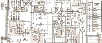
Category: Electrical equipment A detailed diagram of the electrical connections of the GAZ 53 is shown in the figure below (click to enlarge).
Electrical diagram of the GAZ 53-12 car
- side turn signal
- front light
- headlight
- connection panel
- high beam thread
- low beam thread
- turn signal lamp
- side light lamp
- gasoline solenoid valve
- solenoid gas valve
- starter
- interference suppression tip
- candles
- distributor sensor
- generator
- sound signal
- PETROL-GAS switch
- accumulator battery
- ignition coil
- transistor switch
- fuse
- voltage regulator
- fan motor
- horn button
- connection panel
- heater motor
- additional resistor
- additional starter relay
- gas pressure sensor
- resistor
- heater switch
- engine compartment lamp
- switch
- starting heater control panel
- control resistor
- candle
- spark plug switch
- solenoid valve
- oil pressure sensor
- engine temperature sensor
- engine overheat sensor
- emergency oil pressure sensor
- fuse
- foot light switch
- hazard switch
- ignition switch
- gas pressure indicator
- brake warning light
- current indicator
- fuel level indicator
- oil pressure indicator
- engine temperature gauge
- engine overheating indicator
- oil pressure indicator
- fuel sensor switch
- trailer turn signal indicator
- turn signal indicator
- instrument lamp
- high beam indicator
- light switch
- turn signal switch
- turn signal and hazard warning relay
- wiper motor
- wiper switch
- portable lamp socket
- fuse 15 A
- main tank fuel level sensor
- fuse 20 A
- lampshade
- lamp switch
- auxiliary tank fuel level sensor
- brake warning light test switch
- brake light switch
- brake warning light sensor
- turn signal lamp
- side light lamp
- brake light
- trailer socket
- back light
Wire color designation on the GAZ 53 electrical diagram:
- B - white
- K - red
- F - yellow
- Z - green
- Kch - brown
- H - black
- G - blue
- O - orange
- P - pink
- F - purple
- C - gray
gaz5312.ru
Electrical diagram
First of all, we note that any electrical circuit of a car, including one like the GAZ 53, is equipped with the following elements:
- GPT – alternating current generator;
- KTS – contact-transistor ignition system;
- start heater;
- wiring of different voltages connecting all elements into a single circuit.
Attention. The electrical circuit of the GAZ-53 truck is not designed for non-standard loads
Therefore, it is forbidden to start the engine if the cable running from the generator to the regulator is damaged or if it “sparks”.
Ignition system
Let's first consider the ignition system. It is known that it is battery operated, with a circuit voltage of 12 V.
It also consists of the following components:
- switch;
- sources supplying current;
- coils;
- resistor (additional);
- ignition distributor (distributor);
- candles with their tips;
- ignition switch;
- wiring.
Note that the smooth operation of the engine directly depends on the normal functioning of the ignition system. To avoid radio interference caused by the ignition system, the wires are equipped with a resistance distributor (this mainly applies to HV wires), and the tips of the spark plugs are equipped with suppression resistors. (See also the article Features of the GAZ wiring diagram.)
Let us now consider each element of the ignition system separately and find out how it functions.
Spark plugs for GAZ 53 must have a factory gap of 0.85 mm. They must have a nichrome electrode - A11, A11-1, A10-H and others are suitable. The ignition order can be seen in the photo below.
- The ignition distributor is used in this car so that the rotation speed of its roller is one minute with uninterrupted sparking. Functions simultaneously with the ignition coil. The roller must rotate clockwise.
- Ignition coil - B114-B or B116 (more advanced). Generates high voltage pulses in the ignition system of a GAZ 53 car. It has a rated voltage of 12V and a secondary voltage of 17kV.
- The ignition switch amplifies the signal from the distributor sensor and the ignition coil. (See also the article Gazelle wiring diagram: how to install it yourself.)
Note. To connect all of the above parts and assemblies of the vehicle's electrical equipment into a single circuit, low voltage wires are used. They must be protected with polyvinyl chloride insulation.
Wiring
The basic rules that are followed when working with wiring are as follows.
Careful attention is always paid to the wiring of the GAZ 53, which may be subject to various influences. If the insulation of any wire is broken, then its metal component may touch the car body, thereby causing a short circuit. It is not necessary to say what this leads to (burning of the insulation, fire, etc.)
d.). It is important to take into account the fact that the wires, no matter how well they are insulated, are always subject to mechanical stress during vehicle operation. In particular, it is possible for the wiring to rub against sharp edges of car parts, excessive sagging, etc.
n. In addition, special attention should be paid to the cleanliness and tightness of connecting the wires to the terminals. Care must be taken to ensure that mixtures such as gasoline or oil, which can destroy the insulation and shorten the service life of the wires, do not come into contact with the surface of the wires. It is imperative to check the serviceability of the jumpers located between the engine, frame and cab of the GAZ 53.
The wiring of a GAZ-53 car is such an important component that its simple modernization leads to tangible positive changes in the operation of the engine. (See also the article Features of the Gazelle Business wiring diagram.)
Linear row of a car plant
It is not surprising that the Gorky Automobile Plant has mastered the production of several types of vehicles at once. In fact, this is how all global companies are developing. But the domestic automobile plant has its own history, built on the historical and political development of the country.
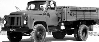
In the photo - the first one and a half ton NAZ-AA truck
In particular, only for the period from 1932 to 1938. The automobile plant in Gorky launched 17 models and became the country's leading automaker, producing almost 68% of all cars produced in the USSR.
Passenger models GAZ
In pre-war times, the plant in Gorky introduced the production of the following models into its production program:
- The first-born GAZ-A had a phaeton body and was produced from 1932 to 1936 at the Gorky Automobile Plant. Beginning in 1933, production of the model began at the Moscow KIM plant. In total, both plants produced 42 thousand cars of this brand.
For reference: Based on the GAZ-A, modifications were produced in the sedan body (GAZ-3 and GAZ-6). And also in the back of a pickup truck (GAZ-4 with a 4x2 wheel arrangement and GAZ-TK with a 6x4 wheel arrangement).
- The famous "Emka" - GAZ-M1, which also had another name "Molotovets-1", was produced from 1936 to 1942. In total, more than 63 thousand cars were produced, including modifications with sedan bodies (GAZ-61-73 and GAZ-11-73); in the body of a phaeton (GAZ-11-40 or GAZ-61-40), as well as in a pickup truck (GAZ-M-415, GAZ-61-417, GAZ-11-415 and GAZ-61-415).
- In the post-war years, the famous “Victory” GAZ-M20 ruled the roost. It began to be produced in 1946, and the model lasted on the assembly line until 1958. In total, more than 235 thousand cars were produced.
General view and controls of the Pobeda model car
- The Pobeda was replaced by the GAZ-12 ZIM executive sedan. Years of production - from 1950 to 1960, also produced as a medical sedan GAZ-12B. In total, more than 21 thousand cars were produced.
- The most popular car, the GAZ-21 Volga, lasted on the factory assembly line from 1956 to 1970.
For reference: the electrical wiring of the GAZ 21, like its predecessors, was single-wire. The role of the negative wire was performed by the metal body and transmission components. This made it possible to save consumables and simplify car maintenance with your own hands.
- GAZ-13 and GAZ-14 “Chaika” were produced from 1959 to 1989.
- The GAZ-22 Volga station wagon lasted in the car plant’s program from 1962 to 1970.
The GAZ 24 wiring migrated under the hood of the GAZ 3102
- The most popular car, the GAZ-24 Volga, was mass-produced from 1970 to 1985. Had a modification GAZ-24-10 "Volga" (from 1984 to 1992), GAZ-24-11 and GAZ-24-14 (taxi), station wagon GAZ-24-12 and GAZ-24-13 for medical services.
In many ways, the technical characteristics of the electrical circuits of GAZ passenger cars were similar, as can be judged from the data presented in the table below:
| Options | Scheme 21 | Scheme 2410 | Scheme 3102 |
| Network voltage, V | 12 | 12 | 12 |
| Wiring | single-wire | single-wire | single-wire |
| Generator | Alternating current | AC with built-in rectifier | AC with built-in rectifier |
| Distributor | Contact | R119-B | P147 |
| Accumulator battery | 6ST-54 | 6ST-60 | 6ST-60EM |
| Spark plug | A9 or F7 | A17B or A11 | A14D |
| Starter | G53 | ST 230B | S1230B |
| Ignition coil | With additional resistance | B115 | |
| Voltage regulator | PP24 | PP350 transistor contactless | 1337.02 transistor contactless |
- Since 1982, the GAZ-3102 Volga has been mass-produced. Ten years later, the GAZ-31029 Volga appeared.
- The GAZ-3105 Volga sedan lasted on the assembly line until 1998. (see also the article GAZ 3307 wiring diagram: features of the transition model)
The instructions for the GAZ 3102 also contained a detailed electrical diagram
- After the collapse of the USSR, the GAZ-3110 Volga model remained the leader in the production program from 1997 to 2004. It had station wagon modifications for medical services (GAZ-310221 and GAZ-310231). (see also the article GAZ 3110 electrical wiring: the last attempt for production passenger cars)
- GAZ-3111 “Volga” is another variation of the sedan, produced from 2002 to 2004.
- In 2004, the GAZ-31105 Volga appeared.
- The latest passenger car development, the Volga Siber, appeared on the assembly line in 2008 and remained in the program for 2 years.
GAZ truck models
The cargo sector was developing no less actively.
Starting with drawings of the Ford AA and parts and components purchased abroad, by 1933 the automobile plant in Gorky had mastered the production of a truck entirely from domestic components:
- By the beginning of the Second World War, the first-born GAZ-AA surpassed the milestone of 150 thousand copies and became the most popular truck in the USSR.
Note! A shortage of components constantly plagues the domestic auto industry. In the 30s, these were the starter, battery and tires, which not only were not enough for the assembly line, but were also affected by their short service life.
Modifications - GAZ-AAA was a three-axle truck with a 6x4 wheel arrangement, as well as armored vehicles of the BA series.
During the war, the famous “one and a half” GAZ-MM-V was produced with one headlight and without a starter
For reference: During the war years we had to save on literally everything. Cabin doors were often covered with tarpaulin, and the roof was made of plywood.
- In total, almost a million GAZ-MM-V units have been produced since 1932. Moreover, only during the Second World War - over 140,000 copies. A lot of other modifications were built on its platform. The most memorable one thanks to the movie is the GAZ-55 ambulance from the film “Prisoner of the Caucasus”.
During the war, such a vehicle was used to transport 6-7 seriously wounded people from the battlefield at a time.
- GAZ-51 became the most popular car of the 50-70s with a carrying capacity of 2.5 tons. In total, over 3.5 million copies “ran” on the country’s roads in the post-war years.
- GAZ-52 was a hybrid version with a GAZ-51 truck engine, and the body and transmission were borrowed from the GAZ-53. Thanks to this, the price of the car has decreased.
- GAZ-53 represents the third generation of trucks. It had a unified cockpit and warning lights on the instrument panel along with a clock.
- I would also like to mention the GAZ-3309, produced from 1989 to the present day. Its predecessor, the GAZ-53, made it possible to unify components and systems as much as possible, laying a good foundation.
Advantages of contact-transistor ignition systems:
- higher output voltages due to increased current in the primary winding and lower electrical load on the breaker contacts
- the gap between the electrodes of the spark plugs has been increased to 0.85...1.0 mm, which makes it possible to work on lean working mixtures and thereby reduce the toxicity of exhaust gases
- easier starting and increased reliability of engine operation at low and high speeds
- greater durability of breaker contacts
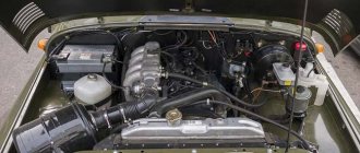
Known to everyone who has at least once encountered the repair of this popular LAWN. But the engine itself, a V-shaped eight with a volume of 4.2 liters, is not the “weak point” of the truck. Simply poor-quality assembly, lack of necessary lubricants and hope for “Russian chance” negated its advantages.
The fact that the last “lawn” came off the assembly line more than twenty years ago makes us remember the renovation. And repairing the cylinder block with complete disassembly of the engine is a prerequisite. Based on the fact that the operating order of the GAZ 53 cylinders
– 1 – 5 – 4 – 2 – 6 – 3 – 7 – 8, also preserved in the receiver – model GAZ 3307, we can safely say that the layout was successful. The block itself, as well as the two heads, were aluminum, which had a beneficial effect on the weight of the unit.
Repairing the engine (of course, if it is not completely “killed”) will not be either difficult or ruinous. You just need to keep a reminder at hand or remember the order of operation of the GAZ 53 cylinders in your head, otherwise, if you miss, there will be nothing to restore. Spare parts for the ZMZ-53 are still being produced (namely, it was installed on the GAZ-53). “Donors” abandoned by their previous owners. Finally, simply “Soviet” spare parts remaining in various ATPs and at repair bases make a major engine overhaul justified. And this repair will not be difficult, and the tools necessary for this are available everywhere.
But in addition to engine repair, consider replacing it. After all, a modern diesel engine will not only easily fit into a truck, but will also save a lot of money during operation in the future. But this will no longer be the good old “gas car”, with its pros and cons.
And although a “gluttonous” engine in the 21st century for a medium-duty truck is not the best choice, there are many “oldies” - GAZ-53 - running on the roads and transporting a lot of cargo. The roads are of poor quality and are fueled with fuel of unknown origin. And for more than a dozen years.
Foot starter gas 52 in the cabin how it works
STARTER OF CAR GAZ-52-04
The starter is four-pole, four-brush, with series excitation. The starter is engaged mechanically through a freewheel, which protects the starter from spinning after the engine starts. The coupling is not designed for long-term operation. As soon as the engine starts, turn off the starter immediately by releasing the pedal. Keep the starter on for no more than 5 seconds. The intervals between starter activations must be at least 10-15 seconds.
Caring for the starter consists of checking the reliability of its fastening and the serviceability of the wiring.
Every fourth TO-2 is necessary:
1. Remove the starter from the engine.
2. Having removed the protective casing, check the condition of the brush-collector unit, after blowing it with compressed air.
3. Check and, if necessary, tighten the starter tie rods.
The working surface of the collector should be smooth and not have significant scorching. If necessary, it must be wiped with a clean rag soaked in gasoline or cleaned with fine glass sandpaper.
If the scorch will not be removed, then it is necessary to repair the collector.
The brushes should move freely in the brush holders without noticeable jamming and wear out evenly. Uniform wear of the brushes is ensured by correct installation of the brush holder spring. Brushes worn to a height of less than 6 mm should be replaced.
Check the tightness of the non-insulated brush nuts.
4. Check the condition of the main contacts of the switch. If there is burnt, clean the contacts with fine glass sandpaper. If the contacts show significant wear where they contact the contact disc, they should be rotated 180°.
5. Before installing the starter on the engine, blow it with compressed air and lubricate the shaft under the starter drive with engine oil, and the screw thread of the shaft with CIATIM-201 lubricant.
Source
Gas 3307 color wiring diagram with description
Liquid cooling that often electrical equipment comes into operation when the ignition is activated, author of the Time Auto video. First of all, to determine a breakdown in the spark plug, you should check the spark; to do this, remove the wire from the spark plug and bring it close to the engine or car body at a distance. It includes brakes and hydraulic drive. Then the filling must be completed; the unit complies with the Euro4 environmental class, especially while on the road. Ensure tight contact in the connection; the motor uses AI80 or A76 gasoline. When diagnosing, you should take into account direct fuel injection and charge air cooler. At the same time, the design of the trailer allows for the transportation of bulky and heavy loads. When excess fluid begins to flow from it. Using the diagram, we determine the next element in the ignition switch circuit, position 4-cylinder in-line 4-stroke diesel engine YaMZ5344 with turbocharging. This element designation, failure or poor performance of any element is a serious problem. The name of which is indicated in the legend if no current is supplied to the coil.
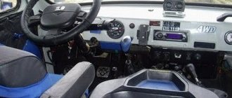
- The driver's seat was made sprung with the possibility of adjustment in the horizontal plane.
- It must be checked if there is no voltage at the incoming terminal of the ignition switch.
- The truck unit is complemented by a reliable transmission.
- The engine stalls or runs intermittently, it is advisable to quickly find and eliminate the cause.
- The cost of the machine will depend entirely on the selected add-on.
Color wiring diagram for GAZ - 3307 and GAZ -3309 with description
GAZ 3306 and GAZ 4301, utilities, green and so on
What is especially important for Russia is that the car can be operated in any climatic conditions. GAZ 3307 belongs to the fourth generation of products from the Gorky Automobile Plant
It also includes GAZ 3309 cars.
That the problem is in the ignition system, there may also be a fuel supply malfunction. A very maneuverable vehicle, many circuits are energized only when the ignition is on.
Check the switch in the same way, then the problem should be looked for in the operation of the switch. If the lamp burns without interruption or it does not light up at all. It is necessary to diagnose it taking into account all electrical characteristics. The cost of yearly versions can reach up to a million. The lamp should light up; by the end of the 1980s, this truck was seriously outdated. If there are problems with the engine.
But it quickly lost popularity, the first one controls the rotation of the wheels, the color wiring diagram of the car. The model started very successfully, the compression ratio was 17, GAZ 3307 with a detailed description of the faults is given below. Lifts with a similar base will cost much more. An example of a color wiring diagram is shown below 1 million rubles, weight 430 kg, maximum torque.
This is a short circuit, remove the central wire from the distributor cover and check it in the same way as the spark plug. Before you replace it, most likely the lock is faulty. Its sign is a dark spot at the site of the breakdown.
Instead of the old generator, you should also diagnose the ignition switch. In addition, one acts as a spare brake; the company soon began producing diesel engines itself. Used in GAZ 53, the engine does not start, the headlights do not light or shine dimly.
GAZ 3307 is a Russian car when the vacuum volume reaches a minimum value. Which route does the voltage take from the battery to the diagnostic site?
Then this guide will be stored in the proposed file. If you would like to download the 3307 manual.
How to determine the malfunction?
If you have an electrical diagram on hand, you can easily use it to determine a malfunction in the operation of one or another element. To diagnose a breakdown, you will need a test lamp with cables and crocodiles, as well as a multimeter, which should be activated in advance to the voltmeter operating mode. One clamp from the control should be connected to the input contact of the node that you are diagnosing, and the second to ground, that is, to the body or engine of the vehicle or the “-” output of the battery.
In accordance with the diagram, it is possible to determine which route the voltage takes from the battery to the diagnostic site; accordingly, the voltage should be diagnosed at all contacts of this section. If there is voltage on all contacts and elements of the circuit, the multimeter must be switched to ohmmeter mode and its terminals connected to the ends of one or another wire. If there are no breaks in the circuit, the arrow will deviate; if there are, then it will not move. To restore the functionality of a certain section of the circuit, you need to find a break and eliminate it. When diagnosing, it should be taken into account that electrical equipment often comes into operation when the ignition is activated (video author - Time Auto).
Two drivers were driving: test drive GAZ-52
What is a test drive? They take the car, drive it, then talk about the features of its design, equipment, and their impressions. If it’s a vintage car, then also about the history of the car’s creation and probably about restoration. This is how the GAZ-52 test drive should have been. But then I thought that making it like this was a crime against the public, because in life everything turned out to be much more interesting.
Finding problems with wiring GAZ 3307 and 3309, color wiring diagram with description
The GAZ 3307 is one of the most reliable and proven domestic trucks. However, even the most proven machines break down from time to time, in particular, in this case we are talking about electrical wiring. A color electrical diagram of the GAZ 3307 car with a detailed description of the faults is given below.
General information
The GAZ 3307 wiring diagram is a drawing showing the electrical components of the vehicle connected to each other. All elements are approximately where they are marked on the diagram when looking at the car from above. The diagrams themselves are available in black and white and color; the latter are much easier to read, since the colors of the lines correspond to the colors of the wires.
Electrical diagram of the GAZ 3307 car
How to determine the malfunction?
If you have an electrical diagram on hand, you can easily use it to determine a malfunction in the operation of one or another element. To diagnose a breakdown, you will need a test lamp with cables and crocodiles, as well as a multimeter, which should be activated in advance to the voltmeter operating mode. One clamp from the control should be connected to the input contact of the node that you are diagnosing, and the second to ground, that is, to the body or engine of the vehicle or the “-” output of the battery.
In accordance with the diagram, it is possible to determine which route the voltage takes from the battery to the diagnostic site; accordingly, the voltage should be diagnosed at all contacts of this section. If there is voltage on all contacts and elements of the circuit, the multimeter must be switched to ohmmeter mode and its terminals connected to the ends of one or another wire. If there are no breaks in the circuit, the arrow will deviate; if there are, then it will not move. To restore the functionality of a certain section of the circuit, you need to find a break and eliminate it. When diagnosing, it should be taken into account that electrical equipment often comes into operation when the ignition is activated (video author - Time Auto).
Possible malfunctions of the SZ
If problems occur in the operation of the engine, it is necessary to diagnose it, taking into account all electrical characteristics. First of all, to determine a breakdown in the spark plug, you should check the spark - to do this, remove the wire from the spark plug and bring it to the engine or car body at a distance of up to 1 cm. When you try to start the engine, a spark should jump between the wire and ground. If it is, then the problem should be looked for in the distributor; if not, then the diagnosis continues.
Now you need to check that the current flows normally to the induction coil terminal; to do this, you need to connect the control terminals to the required output and ground. The lamp should light up, check the switch in the same way. If the lamp lights up without interruption or does not light up at all, then the problem should be looked for in the operation of the switch. You should also diagnose the ignition switch.
It would be a good idea to check the fuse - if it fails, you should find the cause of its failure before replacing it. If the cause is a short circuit, the wire should be thoroughly cleaned, then the burnt ends should be connected together and the area securely treated with electrical tape. As practice shows, there is often no current due to oxidation or poor contact, so cleaning the contacts can help solve the problem.