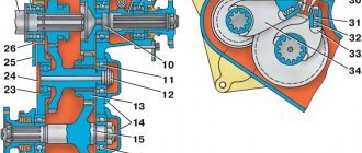
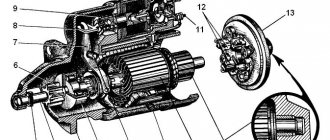
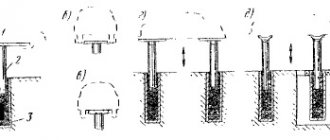
Transfer case: 1 – drive shaft (secondary shaft of the gearbox); 2 – bearing of the drive shaft (secondary shaft of the gearbox); 3 – drive gear (gear for direct and downshift gears); 4, 7 – rear axle drive shaft bearings; 5 – speedometer driven gear; 6 – speedometer drive gear; 8, 21 – cuffs; 9, 22 – flanges; 10 – rear axle drive shaft; 11, 23 – intermediate shaft bearings; 12 – intermediate shaft; 13 – gear for engaging the front and rear axles; 14 – bearing caps; 15 – front axle drive shaft; 16, 20 – front axle drive shaft bearings; 17 – crankcase cover; 18 – crankcase; 19 – drain plug; 24 – plug; 25 – suspension plate; 26 – thrust cup of the bearing; 27 – hatch cover; 28 – cover of the switching mechanism; 29 – fork rod for direct and downshift gears; 30 – front axle fork rod; 31 – locking ball; 32 – retainer spring; 33 – front axle shift fork; 34 – forward and downshift fork
The transfer case is two-stage, mechanical, and has an additional reduction gear (Fig. 3.49).
Some vehicles can be equipped with a modernized “small-module” transfer case, in which the gear teeth of the front and rear axles, as well as the toothed rims of the rear and front axle drive shafts, are made with a 2.5 mm module (instead of 3.5). At the same time, the low gear ratio decreased and became 1.47 (instead of 1.94).
The transfer cases are interchangeable and look no different. The modified parts differ from similar parts with a 3.5 mm tooth module in the number of teeth
Possible breakdowns and diagnostics
Below is a description of the main breakdowns of transfer gearboxes:
- Damage or natural wear of rubber seals, leading to oil leakage from the crankcase. Gears operating under oil starvation conditions wear out. Metal particles that get into the bearings and the contact patch between the teeth accelerate the wear of the rubbing surfaces. Oil leakage is noticeable upon visual inspection of the transfer case.
- Mechanical damage to parts affects the noise level of the unit. Damaged gears spontaneously disengage. In this case, there may be no oil leaks.
- The destruction of the rolling bearing leads to the appearance of crunching metallic sounds; With severe wear, the shafts become jammed.
- The Dymos transfer gearbox is equipped with an electronic controller that displays information about a malfunction. When the 4H and 4L indicators and the 4WD Check sign turn on at the same time, it is necessary to diagnose the unit. Increased noise during operation indicates stretching of the metal chain transmitting torque.
Service
Before using the transfer case on the UAZ “Loaf”, it is always useful to read about the rules for its maintenance. Like any drive, it lasts longer the more regularly and attentively the owner carries out the service.
What's in the program:
- external inspection before using the transfer case on a UAZ (every drive on a difficult route) - we look for oil leaks, cracks, chips, and other defects;
- checking fasteners (shafts must be fixed securely);
- Changing the oil in the UAZ transfer case.
An important point: the transfer case should be checked for leaks or mechanical damage every time after its use. In addition, when wading, water sometimes gets into the transfer case crater (through the breathing valve). To prevent this from happening, a flexible tube is usually used (one end to the valve outlet, the other under the hood of the car).
Mechanism adjustment
After assembling and installing the new switching mechanism, it is necessary to adjust the rods and the entire system. The goal is achieved by changing the length of the vertical and horizontal rods. Do-it-yourself setup sequence:
- Move the gear shift lever to the neutral position, and move the element responsible for selecting the gear all the way.
- Move lever 1 to positions corresponding to speeds 1 and 2. While checking that the elements are not pulled up, connect and secure the selection rod.
- Similar actions must be carried out for other gear stages.
After work, you should check that the gears are fully engaged by starting first gear and reverse. The lever must not come into contact with other parts or controls. The optimal gap size is up to 3 mm.
Transfer case housing
The transfer case housing for the UAZ 469 car is cast from cast iron. In the plane of the housing there is a connector perpendicular to the axes of the shafts. Two tubular pins determine the relative position of the body halves. The crankcase assembly and cover are processed mechanically. Because of this, they are not individually interchangeable.
There is a hatch on top of the crankcase. It is closed with a lid. If necessary, a power take-off mechanism is installed here. The gearbox is centered on the gearbox along a double-row angular contact bearing through an intermediate cup. Between the two boxes are a suspension plate and sealing gaskets.
Carter RK is assembled from two halves. To prevent the leakage of oil circulating in the cavities of the transfer case during its operation, a sealing gasket is installed between them. In the places where the shafts are installed, which extend outward from the housing, oil seals are placed. They reliably hold lubricants inside the unit while the vehicle is moving.
The operation of the transfer case, gears and shafts is associated with increased loads. When overcoming obstacles, when all mechanisms are involved, metal parts heat up. The oily substance inside the housing evaporates and gases accumulate in the cavities.
In order to avoid depressurization, in order to remove harmful accumulations from the crankcase to the outside, the manufacturer has provided for installing a special breathing valve - a breather - on top of the transfer case housing. This device ensures communication between the internal cavities of the crankcase and the atmosphere.
Node purpose
The UAZ 469 transfer case is designed for efficient vehicle driving off-road, rough terrain, and driving on roads without asphalt. When the car overcomes difficult, difficult areas of forest or swampy terrain, reducing torque with the help of the steering wheel significantly reduces the degree of wheel slip.
All car models produced by the Ulyanovsk Automobile Plant are distinguished by an increased degree of cross-country ability, excellent handling, and the ability to overcome any off-road conditions. The RK increases the vehicle’s maneuverability and cross-country ability, allowing you to quickly move on roads of varying quality without any problems. The UAZ transfer case is activated mechanically from inside the car using two levers.
The rear drive axle of the UAZ 469 is constantly on. The front drive axle is connected as needed when the vehicle overcomes obstacles. Driving on good asphalt roads is carried out with the front drive axle disabled. In such conditions, it works like a simple front axle of a car.
IMPORTANT! When driving a UAZ vehicle for a long time on a high-quality road with asphalt or concrete pavement, operating the vehicle with the front drive axle constantly engaged is prohibited. This will lead to breakdown of transfer case components and jamming of rotation parts.
Do-it-yourself dismantling of the speed box
What tools are needed to repair a transmission? To carry out repairs, you should acquire a complete repair kit. In particular, you will need open-end and socket wrenches, a hammer, screwdrivers, and a mounting blade.
How to remove the box? To begin the procedure for removing the checkpoint, you should perform the following steps:
- The UAZ stands on the inspection hole.
- The transmission oil is drained (this will lighten the weight of the box a little).
- The seats in the cabin are dismantled.
- The clutch release fork, frame, cardan, speedometer shaft, clutch pan, and muffler adjacent to the transfer case must be removed. The slide must be removed.
- The transfer case must be disconnected from the main gearbox. As a rule, the transfer case is wrapped with rope and suspended.
- All consumable parts (bolts, nuts, etc.) are unscrewed.
- Since the UAZ gearbox is fixed on fasteners, they need to be unscrewed and the box can be removed from the splines.
Summary
Summarizing the above, it is worth concluding that the transfer case in modern UAZs is a completely reliable mechanism (both the mechanics and the new version). But it requires good maintenance, without which it can doom the car owner to significant costs.
Do you check the condition of the transfer case before each off-road ride? Tell us exactly how. Maybe your friends know what other features mechanical (old) and chain (new) devices have? Be sure to share this article with experts and beginners so that useful tips and important questions will be added in the comments, which our experts will definitely answer in the following materials.
Source
general information
First, let's figure out what this part is and why it is needed? The transfer case is a unit that is responsible for distributing torque from the car’s engine to multiple drive mechanisms, and they quite often increase the number of gears in the transmission.
Some cars of this brand are equipped with an improved small-module box. In such a box, the teeth of the gears of the front and rear axles, the teeth of the rims of the drive rollers of the front and rear axles are made with a module of 2.5 mm (in other transfer cases - 3.5 mm). The transfer cases can be replaced with each other, and in addition, they are exactly the same in appearance.
Maintenance
Like any other car part, the transfer case also requires some maintenance. So, the necessary maintenance:
Check the oil level regularly to ensure timely replacement.
Please note that during vehicle operation, the oil level in the gearbox may drop by up to 8 mm relative to the lower edge of the filler hole, as well as its increase. In this case, there is no need to equalize the oil level, because the total volume of oil contributes to the normal functioning of both units. Check all fastenings regularly; In case of oil leakage, it is necessary to detect and eliminate the cause, namely, replace failed cuffs, plugs, gaskets, etc.;
Common problems and causes of their occurrence
Transfer case UAZ Patriot
Possible problems with the gearbox of a UAZ Patriot:
- The teeth of the gears are broken;
- Oil leaks through the seals;
- The distributors are humming, the gearbox of the UAZ Patriot is noisy;
- Bearings are worn out or destroyed;
- The downshift switches off automatically.
Now let's look at the causes of problems with the UAZ Patriot transfer case:
- The transfer case is poorly screwed on;
- The UAZ Patriot engine mount is broken;
- Low quality of parts, namely oil seals and bearings;
- Long-term driving and use of incorrectly inflated wheels;
- Long-term driving with a connected front axle;
- The transfer case of the UAZ Patriot car is worn out. Quite often this happens due to low quality or lack of the required amount of gear oil;
- Huge overloads during operation either due to necessity or little driving experience;
- Untimely replacement of transmission oil;
- The driveshaft is beating. Quite often this happens due to poor quality of the shaft, damage to the crosspieces, destruction of the outboard bearing or untimely injection;
- Use with a brand of gear oil that does not correspond to the intended purpose or season;
- There is no lubrication in the spline joint of the propeller shaft;
- Poor quality tuning, namely the stroke and length of the driveshaft does not correspond to the changes made;
- Not very high-quality tuning, namely incorrect transmission ratios.
Some tips on the topic of the UAZ Patriot transfer case:
Please note that the front axle must always be switched off, unless absolutely necessary; The transfer case is not equipped with a center differential, and this has a significant impact on its life when the front axle is connected constantly or for a sufficiently long time.
Safety precautions when performing work
To avoid injury when changing the oil in the transfer case, you must:
- Install wheel chocks under the vehicle wheels. This will prevent the car from rolling spontaneously;
- When dismantling the drain plug, it must be kept at a distance from the transfer case. Hot oil from the transfer case can cause burns if it comes into contact with the skin;
- Personal protective equipment such as gloves and goggles should be used to protect eyes and skin.
From the above it follows that the UAZ 469 transfer case is necessary to improve off-road performance. The design of the RK allows you to connect the front axle and reduce the torque from the gearbox. For normal operation, the unit must be serviced regularly.
Source
UAZ 469 / Happiness In Darkness › Logbook › Restoration, assembly - Gearbox repair part 18
The bolts securing the forks on the gearbox cover turned out to be slightly unscrewed, i.e. spun by hand. Tightened the bolts:
Put the gearbox cover in place:
Turn on the 4th speed and look at the position of the fork from the side of the gearshift knob:
We look at the position of the 3-4 gear clutch and the location of the crackers:
We look at the position of the fork from the inside of the gearbox cover:
Everything seems to be normal, but the 4th speed can be turned on “Further”...
Turn on the 4th speed “Next” and look at the position of the fork from the side of the gearshift knob:
We look at the position of the 3-4 gear clutch and the location of the crackers when turning on the 4th speed “Next”:
As you can see, the coupling has also moved further, because nothing limits it, and the balls of crackers began to peek out from the clutch... This can cause the crackers to come out, eat the synchronizer ring and jam the 4th gear.
We look at the position of the fork from the inside of the gearbox cover when turning on the 4th speed “Next”:
We need to solve the problem, now I think I understand that I read somewhere about washers limiting the travel of the fork, now it’s clear where to put them...
We look at the gap that allows the plug to turn on further:
It turns out 6 mm
. You need to select a washer of the required diameter, 6 mm thick, in order to prevent the plug from turning on “Next”.
Let's disassemble the mechanism for moving the 3rd and 4th gear forks:
Repair of UAZ Bukhanka transfer case
Serious repairs to the UAZ transfer case are rarely performed. As a rule, to restore normal operation, adjusting the product and lubricating problem areas is enough. If repairs cannot be avoided, then the operation to return the box to its former functionality is done in strict order.
Manipulations performed:
- Dismantling the transfer case;
- Disassembling the transfer case;
- Fault detection;
- Troubleshooting (replacement, restoration of parts);
- Transfer case assembly;
- Installing the transfer case in place;
- Functionality check and configuration.
Disassembling the box:
Before carrying out work, select the necessary tools; for this, find out the type and type of transfer case. Functionally, repair is the replacement of damaged parts with new ones, for this reason more attention is paid to the rejection stage.
Subject to replacement:
- Oil seals (changed during disassembly, regardless of the degree of wear);
- Gears (parts cannot be repaired due to the loads they experience);
- Forks and splines (elements affect the quality of work and safety);
- Bearings;
- Protective casing (if cracks or chips are detected, the part is replaced).
UAZ transfer case control mechanism:
Stages and main points of repair
Repair of the transfer case takes place in several stages.
- Removing and disassembling the box.
- Troubleshooting.
- Eliminate these faults by replacing the part or repairing it.
- Assembling and installing the box in place.
To remove the box and disassemble the UAZ 469 transfer case, you need to proceed as follows:
- drive the car into the inspection hole;
- lower the parking brake lever and put the gear levers and transfer case in neutral;
- then the casing and lining are unscrewed one by one, the handles and covers are removed, and all wires are disconnected.
Before you start disassembling the device, you need to wash it and drain all the oil. For ease of disassembly, it is better to use a special stand where the transfer case can be secured.
When disassembling the differential, it is advisable to mark on its body the relative positions of the driven gear mounting bolts, so that later it will be easier to put everything back in place.
Disassembling the UAZ gear shift mechanism
Disassembling the gear shift mechanism SEQUENCE OF ACTIONS
Using a narrow slotted screwdriver, we knock out the plugs of the gear shift mechanism rods.
Using the “17” key, unscrew the plug-plug of the latch socket.
Using pliers, remove the safety wire of the bolts securing the forks to the rods...
...and use a 10mm wrench to unscrew the three bolts.
We use a beard to knock out the fork rod of 1st–2nd gears along with the plug.
We take out the plug and stem. In order not to confuse the rods, we immediately put the forks on them and secure them with bolts. Similarly, we knock out the fork rod of III–IV gears),…
The middle rod contains a locking pin. By knocking out the reverse gear fork rod,...
...take out the ball with the spring.
Using a 10mm wrench, unscrew the three bolts securing the fuse cover.
We take out the ball with the spring (fuse lock).
We wash the parts in kerosene or diesel fuel and inspect them. Cracks of any shape or length are not allowed on crankcase parts. Bearing seats and holes for gearshift rods must be smooth, without nicks, signs of scuffing or noticeable wear. The bearings should fit into the sockets tightly, by hand force or by lightly tapping through the spacer. The gaskets must be intact, without tears, delaminations or breaks. We check the shafts, axles and rods for cracks, noticeable signs of wear, scoring and metal enveloping. This also applies to the splined parts of the shafts; the mating parts should move easily on the shafts, without noticeable play or jamming. Minor traces of scoring, as well as corrosion (on the splines), are removed with a needle file or very fine sandpaper, and the shaft journals are polished with thin GOI paste or diamond paste. On the teeth of gears and synchronizer couplings, chips, traces of jamming and chipping are unacceptable; on the cones of synchronizer locking rings there should also be no traces of jamming, severe wear and envelopment of bronze on steel. Ball and roller bearings must be in perfect condition. Their rotation should be easy, without jamming, clicking, play or vibration. Fatigue chipping (pitting), noticeable wear and chips are not allowed on raceways, balls and rollers (needles). Ball bearing cages must not touch the rings or have cracks or breaks. After a run of about 100 thousand km, it is better to replace all ball bearings with new ones, regardless of their condition. The cuff of the input shaft, if any, is also replaced. Before assembly, lubricate the bearings, their seats, and shafts with transmission oil. To assemble the roller bearing of the secondary shaft, apply any grease to the rollers. We assemble the gear shift mechanism in the reverse order, starting with installing the fuse. Install the spring and the reverse fork rod retainer ball.
Recessing the ball with a slotted screwdriver, insert the rod into the hole in the cover.
We put the fork on the rod, tapping the end of the rod with a soft metal hammer,...
...and fix it with a locking bolt, aligning the holes of the rod and fork.
We install the plunger into the channel between the reverse gear fork rod and the rod of III–IV gears. Similarly, we install the rod of III–IV gears with a fork and the second plunger (between the rods of III–IV and I–II gears). We install the rod of 1st–2nd gears, the fork, the ball with the spring and the retainer plug. By holding the switching mechanism in a vice and installing a lever on it, we check the correct assembly and operation of the mechanism. The rods should move easily and be clearly fixed. Lock the gearshift fork bolts with safety wire.
We orient the oil deflector washer with its protrusion towards the inner ring of the bearing.
ATTENTION The lever travel when engaging first gear in a gearbox with synchronizers only in III–IV gears is 2.5 times greater than when engaging second gear. Missing first gear causes rapid wear and destruction of gears
Finding faulty parts, repairing and replacing them
Before inspection, all parts must be cleaned with a brush and rinsed.
- Oil seals. They are considered unusable if the wear of their working edge exceeds 1 mm. For any minor damage, the part is replaced with a new one.
- Covers and crankcase. Cracks, dents, chips - all this is a good reason to replace it with new parts. However, for very minor damage, you can get by with simply cleaning the damaged area with a file.
- Gears. Worn teeth and their chipping are a reason to replace the part. Otherwise, this will lead to deterioration in handling on difficult road sections and increased load on the engine.
- Shafts. For these devices, the first thing to check for wear is the splines, working surface and threads. By installing the front and rear drive shafts on the prisms and turning them by hand, as well as the drive shaft, we check the runout of the end part, which should not exceed a tenth of a millimeter.
- Bearings. Check for scratches and other damage to the surface. Any cracks or chips indicate the need to replace the bearing. The work of the part must be flawless. It is important that its turns are carried out without jamming or extraneous sounds. Otherwise, the bearing is unusable and must be replaced.
- Clutch and hub. May have nicks, burrs and burrs, which can only be cleaned with a file. If the ends of the teeth on the coupling are damaged or deformed, the part must be replaced.
- Differential. In case of minor damage to the surface of the satellite axis, they can be sanded with fine-grained sandpaper. If the damage is significant, the axle will have to be replaced.
The UAZ transfer case is assembled in the reverse order to the one in which it was disassembled, and before installing the unit in place, its operation is checked on the stand. The function must be flawless, the assembly must be correct, and it is important that no oil leaks. Tests are carried out first in a higher gear, then in a lower gear.
Under load, check operation in the second mode, in the rest - without load. The serviceability of the differential is checked in the first mode, while gradually slowing down until it comes to a complete stop.
With proper repair and timely replacement of all faulty components, the UAZ transfer case will operate without jamming, knocking or noise, and oil will not leak!
Source
Specifications
Briefly commenting on the tabular information, we conclude the following: the “loaf” has two drive axles, the UAZ “loaf” gearbox is of a mechanical type and, together with the transmission, is a monoblock. Activation is carried out using a demultiplier.
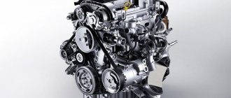
Engine UAZ-452
The engine is a modernized GAZ-21 engine installed inside the cabin. This allows you to make minor repairs without leaving the cab. Good load capacity and cross-country ability retain the title of “SUV” and “all-terrain vehicle”. Specifications
| Modification | Glass van UAZ | UAZ bus |
| Body | ||
| Wheel formula | 4x4 | 4x4 |
| Number of seats | 2 or 5 | 9–10 |
| Length, mm | 4390 | 4363 |
| Width, mm | 1940 | 1940 |
| Height, mm | 2064 | 2064 |
| Wheelbase, mm | 2300 | 2300 |
| Ground clearance, mm | 205 | 205 |
| Fording depth, mm | 500 | 500 |
| Curb weight, kg | 1805 for closed van 1920 for glass van | 2005 – for 9 seater bus 2022 – for 10 seater bus |
| Total weight, kg | 2730 for closed van 2845 for glass van | 2880 |
| Load capacity, kg | 925 | 875 – for a 9 seater bus 865 – for a 10 seater bus |
| Engine | ||
| Engine | Gasoline, ZMZ-40911.10 | |
| Fuel | Gasoline with an octane rating of at least 92 | |
| Working volume, l | 2,693 | |
| Maximum power, hp (kW) | 112.2 (82.5) at 4250 rpm | |
| Maximum torque, Nm | 198 at 2500 rpm | |
| Maximum speed, km/h | 127 | |
| Fuel consumption at 60 km/h, l / 100 km | 9,0 | |
| Fuel consumption at 80 km/h, l / 100 km | 11,2 | |
| Fuel tank capacity, l | 77 | |
| Chassis | ||
| Transmission | 5-speed, manual | |
| Transfer case | 2-speed with front axle drive disabling | |
| Brake system | Dual-circuit, with vacuum booster, front disc, rear drum) | |
| Tires | 225/75 R16 |
Safety
When creating the UAZ, the concept of driver safety was considered a secondary task. The main task was to realize the intended purpose. That is, meeting the requirements of the defense field.
According to some experts, this car has a 30 percent chance of surviving a frontal collision.
UAZ Bukhanka front view
Although, crash tests carried out for the first time in 1971 did not confirm this figure. The design does not provide seat belts, but the good news is that in the UAZ “loaf” line, it has decent strength characteristics.
It is also impossible to deny the fact that traffic safety largely depends on the qualities and experience of the driver himself.
General characteristics
UAZ gearbox
A gearbox is a car's gearbox. The UAZ 469 has a manual 4-speed gearbox equipped with inertia-type synchronizers. They are designed to engage gears without noise or rumble. Synchronizers help equalize the speed of the connecting teeth before engaging. The rotation speeds of the motor and wheels do not match; a synchronizer is needed to combine them. In addition, the gearbox allows the car to move in reverse.
The UAZ 469 gearbox consists of the following parts:
- input shaft;
- front cover;
- special purpose nut;
- auxiliary fasteners;
- auto laying;
- ball bearings;
- secondary shaft drive bearing;
- crankcase;
- coupling for connecting III and IV gears;
- 3rd gear gear;
- 2nd gear gear;
- clutch for connecting 1st and 2nd gears;
- 1st gear gear;
- secondary shaft;
- fastening washer;
- gearbox spacer ring;
- mounting bolt;
- washer for fastening;
- intermediate shaft;
- reverse gear axis;
- reverse gear;
- cork;
- block of gear wheels driving the intermediate shaft and 3rd gear;
- lid.
The device of the UAZ box
If you are interested in the UAZ gearbox diagram, it is easy to find it in photos and drawings posted on various sites on the Internet.
4 studs are screwed into the clutch housing, on which the gearbox is attached. The intermediate shaft drive has gears that are in stable mesh. 1st gear gears have straight teeth, 2nd and 3rd gears have spiral teeth. They are mounted on the drive shaft, supported by needle bearings. The drive shaft has 2 supports. When engaging second gear, the role of the clutch is performed by the first gear. Activation of reverse and first gear occurs due to the movement of gears. Gearbox ball bearings. To prevent movement along the axis, the gears are secured with rear bearings. The rear bearing of the intermediate shaft is integrated with the shaft itself using a bolt.
The switching device has 3 forks attached to the rods with locking screws and located in the side cover. The ball-shaped stopper for neutral position and engaged gears has a rod. The locking blocks located between the rods do not allow connecting 2 gears at the same time. The support contains a lever that helps move the forks. It itself is pressed by a spring to the supporting spherical surface. The boot placed on the lever prevents water and dirt from entering the device. To prevent accidental engagement of reverse gear (the driver may simply get confused), this device contains a fuse - a plunger, which is equipped with a return spring and a ball.
The box lubrication device is combined with the transfer case. Lubricant from the transfer case passes into the UAZ gearbox through a double-row bearing (angular contact) and the existing drain device, after which it returns through the drain hole.
UAZ gearbox repair
The manual gearbox is the most important transmission unit of the UAZ 469 vehicle. The UAZ 469 gearbox has a responsible and fundamental task - monitoring the variability of the engine torque and carrying out transmission from the engine to the driving wheels of the vehicle. The UAZ 469 manual transmission has a fairly long service life. This does not mean that the gearbox does not need repair.
Useful video
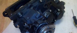
The transfer case (transfer case) is an important transmission unit of all-wheel drive vehicles, designed to transmit torque from the engine to the drive axles. Since 2013, production of the UAZ Patriot, equipped with a Hynday Dymos transfer case manufactured in Korea, began. Unlike previous versions, where the driving modes were regulated by a mechanical lever, a more convenient electromechanical control is used here. Subjected to serious loads, the device requires regular maintenance, and in case of breakdowns, timely repairs, which can be done either in a car service center or with your own hands.
Device and how it works
The transfer case is a mechanism located in a separate housing made of gray cast iron. The assembly is divided vertically into a crankcase and a cover, which are connected by bolts. Both halves undergo joint processing, so it is impossible to install a part from another gearbox. The crankcase has a separate hatch for installing a power take-off. The oil-filled unit with the parking brake drum installed weighs 37 kg.
The transfer gearbox will only work correctly if it is correctly centered on the gearbox housing. For this, a 2-row angular contact bearing and a steel cylindrical cup are used. The gearbox shafts are mounted on ball and roller bearings, secured with nuts and retaining rings, respectively. The output shafts pass through sealing seals installed in the covers.
The drive shaft of the unit is the driven axis of the gearbox, which is equipped with a splined tip on which the gear is located. This part has 2 positions that allow you to get forward and reduced speeds. The shift drive is equipped with a special fuse that prevents the low range from starting until the front wheel drive is connected.
When the gear is connected to the gear wheel of the rear axle drive shaft, direct transmission is ensured. The gearbox device includes a special lever that allows you to move the gear to the side, engaging it with the gear of the intermediate shaft. In this position, the rotation speed of the driveshafts of the axle drives is reduced.
The design of the transfer gearbox has a movable gear wheel mounted on the middle shaft and controlled by a separate lever. This gear provides connection to the front wheel drive. When the gear is disengaged, the gear continues to rotate as it remains in contact with the rear axle drive gear. This operating principle is necessary to spray the oil in the crankcase.
The plant produced several modifications of the transfer gearbox, which differ in the module of installed gears. Because of this, the gear ratio changed - instead of 1.94 it became 1.47. It is possible to remake the old-style transfer case by replacing gears, since the housing design has remained unchanged.
On some cars there is an imported Hyundai Dymos transfer case (Dymos) with electrical control. The unit weighs 32.4 kg, provides direct and low gears (gear ratio 2.542). The unit is equipped with a controller that diagnoses the box and records error codes. The mechanical part of the imported box is very different from the Russian counterpart - instead of gears, a chain drive is used.
The difference between the old-style transfer case.
Torque is transmitted to the transfer case from the gearbox using the drive shaft. Centering is carried out along the outer race of the bearing. The parking brake elements are located on the rear wall.
Important elements of the transfer case are 2 shafts: drive and intermediate. They are fixed by a bearing system. The drive shafts are equipped with gears that ensure their engagement.
The design provides for a lever that is directly controlled. The mechanism is made in the form of rods and forks located at the top. If it is necessary to engage a lower range of gears, the driver must directly operate the lever.
In addition, the system contains a large number of small elements, such as oil seals that protect the system from oil loss, auxiliary bearings and gears.
Causes of breakdowns
As a rule, the need to replace the main components of a gearbox arises due to their natural wear and tear.
Causes of gearbox breakdowns
The main reason for oil leakage from the gearbox is the presence of an increased level of fuel in the system. For UAZ gearboxes, you should use high-quality oil. If the liquid is not of the proper quality, this may cause characteristic noises from the box. When the synchronizer or its parts wear out, it is always difficult to change gears
You should also pay attention to the details of the switching mechanism. When gear teeth are deformed, gears often switch off automatically
Article on the topic: ZF gearbox repair
Causes of transfer case malfunction
This is the unit
Before starting repairs, of course, it is necessary to find out the cause of the malfunction.
- There was a loud noise in the transfer case. This could be the result of loose nuts that connect the transfer case to the transmission or loose bolts on the bearing caps. The list of reasons includes wear of the bearings or gears themselves, poor-quality or unsuitable oil, or its low level.
- Gear selection and shifting work poorly. This usually occurs due to the clutch seizing on the splines of the front drive hub or shafts. Or, alternatively, the gear selector is deformed.
- The transmission switches off spontaneously while the vehicle is moving. The gear teeth may be worn. Also, shutdown may be affected by an increase in the gap in the spline connection or wear of the clamp parts.
- Oil leaks. Often the problem is caused by wear or mechanical damage to the sealing gaskets, loosening of the nuts on the cover, wear of the seals or sealing rings of the actuator rods.
The solution to all these problems is either repair or replacement of faulty parts. In some cases, it will be enough to just tighten the nuts or add oil.
Causes and troubleshooting
The design of the UAZ gearbox is reliable, trouble-free and durable. However, problems with equipment occur due to errors in use and violation of established regulations.
| Source and symptoms | What to do |
| Exceeding the permissible hum level of a working device | |
| Erasing the gear teeth of the box. | Replace worn out box items. |
| Weak fastening of the transfer case to the box, or reduced fixation of the bearing caps. | Tighten the fasteners, if the symptom recurs, dismantle the product and eliminate the defect. |
| Bearings are worn out. | Replace erased items. |
| Saturation of the working fluid with wear products from the box. | Remove the pan, wash it, change the oil. |
| Incorrect oil used, low fluid filling level. | Change the working fluid, set the desired level. |
| Carrying out repairs to replace gears, without selecting a product to minimize noise. | Check the gears for noise and replace them with the required ones. |
| Switching steps is difficult | |
| Different wheel wear. | Replace with wheels with the same tread and equalize the internal pressure. |
| The joints of the longitudinal projections of the main and the mediator shaft are jammed. | Sand the areas with burrs; if that doesn’t help, change the elements. |
| The drive gear has damage on the teeth of the small ring. The shift fork rod is bent. | Sand the damaged areas, straighten the rod, if that doesn’t help, change the element. |
| The switch rods are stuck on the axle. | Separate the parts, clean the axles and pipes, coat with lubricant, and connect the product again. |
| Spontaneous speed shutdown | |
| Erasing the teeth of the gears of the box. | Replace worn out box items. |
| The box bearings are worn out. | Replace worn box elements. |
| A large gap in the articulation of the shaft and gear. | Select the gear according to the size of the longitudinal protrusions. |
| The transmission is unable to engage because the mechanism is bent or there is damage to the gears and cylinders. | Correct bends, sand damage, or replace parts. |
| Poor functioning of the locking mechanism, loss of elasticity of the spring mechanism, abrasion. | Replace erased items. |
| Leakage of working fluid | |
| Violation of the integrity of the sealing elements of the pan, bearing caps, and the transfer case’s articulation with the gearbox. | Replace sealing elements. |
| Weak fastening of the cover, bearing, pan, joints. | Tighten connections. |
| Violation of the integrity of the shaft seals. | Replace the damaged element. |
| Violation of the integrity of the tray or lid. | Replace the damaged element. |
| The plugs of the switching rods, switching rods, and the plugs of the front bearing of the middle shaft fall out or are broken. | Change the plugs. |
| Bearings are damaged | |
| No, or a small amount of lubricant. | Change or add fluid. |
| Demolition of cages and bearing rings due to abrasive. | Change the elements, dismantle and wash the pan, change the working fluid. |
| Excessive shaft bearing friction. | Disconnect the element, clean the product, and coat it with lubricant before reassembling. |
The distributor needs careful handling and periodic inspection. Often, the reason for the breakdown is trivial driving on wheels with a violation of the pressure regime. Continuous use of the front pair of wheels is not allowed; the product is used as needed. Operation is affected by the use of spare parts that do not meet the required quality.
UAZ "Loaf":
Transfer case UAZ-469 transfer case UAZ-469
Details Category: Transmission UAZ-469
Razdatka UAZ-469
Rice. 61. Transfer case UAZ-469.1 - drive shaft; 2 - drive gear: 3 - forward and downshift fork; 4 — rear axle drive shaft; 5 and 10 — rear axle drive shaft bearings; 6 — speedometer drive gear; 7 — speedometer driven gear; 8 — crankcase cover; 9 — oil deflector; 11 - cover; 12, 40 and 42 - thrust rings; 13 — thrust washer; 14 and 50 — oil seals; 15 and 53 - flanges; 16 and 51 — washers; 17, 38, 44, 52 — nuts; 18 - cover; 19 — front axle fork; 20 — grease fitting; 21 — lever for engaging the front axle: 22 — lever for engaging forward and downshift gears; 23 — lever release springs; 24 — washer; 25 — axis of levers; 26 — bracket; 21 — lever for direct and downshift gears; 28 — fork rod for direct and downshift gears; 29 — front axle activation lever; 30 — front axle fork rod; 31 — cover of the switching mechanism of the UAZ-469 transfer case; 32 — retainer ball; 33 — clamp spring; 34 - plug; 35 — front axle fork rod; 36 — fork rod for direct and downshift gears; 37 and 54 — intermediate shaft bearings; 39 — front axle engagement gear; 41 — rear bearing cover; 43 — front axle drive shaft; 45, 48 — front axle drive shaft bearings; 46 — locking plate; 47 — drain plug; 49 — cover; 55 - plug; 56 — intermediate shaft; 57 — thrust cup of the bearing.
All parts on the shaft - front bearing, speedometer drive gear, oil deflector, rear bearing, thrust washer and flange are secured using a special nut and washer. The UAZ-469 transfer case nut is locked by pressing its collar into one of the grooves of the shaft (Fig. 62). The intermediate shaft is made integral with the intermediate gear of the reduction gear and in the rear part has involute splines for seating the front axle engagement gear (Fig. 61 ). The shaft supports are two bearings. The rear bearing on the shaft is secured with a special nut, which is locked by pressing its shoulder into one of the grooves of the shaft (Fig. 62).
Rice. 62. Locking the nuts of the UAZ-469:A transfer case - tool profile.
The front axle drive shaft (Fig. 61) transmits torque to the front propeller shaft and is made integral with the driven gear. The shaft is mounted on two bearings and is fixed in the same way as the intermediate shaft. The transfer case switching mechanism (Fig. 61) has two forks 3 and 19, which with their legs are connected to the movable gears. The forks move along fixed rods and are equipped with spring clamps. There are cutouts in the rods for fixing positions. The shift levers of the UAZ-469 transfer case are located in a separate cover 31, installed on the upper inclined hatch of the crankcase. The cover also serves as a support for placing two movable rods 28 and 30, on which shift levers 27 and 29 are secured with pins. The front ends of the rods extend from the cover and have pins for connection with levers 21 and 22, controlled by the driver. In the front part of the cover, the holes for the rods are sealed with rubber rings. In the rear part, the holes for the rods are closed with plugs. A ball is placed between the rods? 11 mm, which acts as a lock (does not allow downshifting until the front axle is engaged). The hole for the ball and two holes for installing pins in the drivers and rods are closed with plugs. During operation, maintenance is limited to checking the lubricant level and replacing it within the time limits specified in the lubrication table, as well as periodically checking all threaded fasteners. If a leak is detected, find out the cause and replace the faulty parts (gaskets, o-rings, etc.). When changing the lubricant in the UAZ-469 transfer case housing or topping it up, you must simultaneously check the lubricant level in the gearbox. The level should be at the lower edge of the filler holes. The UAZ-469 transfer case has no adjustments. The shift lever axis is lubricated through a grease nipple, accessible from below.
Site about off-road vehicles, SUVs, off-road vehicles
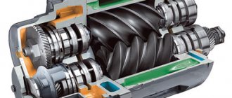
The helical transfer case began to be serially installed on UAZ-3162 Simbir cars. It is 80 percent unified with a spur transfer case, but at the same time contains eleven original parts. The main difference between a helical transfer case and a spur transfer case is the presence of helical gears instead of spur ones to transmit torque to the front axle of the car.
The use of helical gears in the design of the transfer case made it possible to reduce its overall noise level by 8-10 dBA compared to spur gears, but only in the front axle engagement mode. In low gear mode, the noise remained almost the same, since the drive gear for direct and downshift engagement and the reduction gear of the intermediate shaft remained spur-cut.
UAZ helical transfer case.
Mechanical, two-stage, with reduction and neutral gears, without center differential, with the ability to disable the front axle. The speedometer drive can be either 624 or 1000 rpm/kilometer. The downshift ratio remains the same - 1.94. The helical transfer case is designed for use with engines delivering a torque of up to 30 kgm, which is 60% higher than the previous capabilities of a spur gearbox.
The transfer case is attached with four bolts to the rear wall of the transmission housing and sealed with sealant. Centering of the transfer case relative to the gearbox is carried out along the outer race of the double-row bearing of the gearbox secondary shaft. A parking brake mechanism is installed on the rear of the box housing.
The helical transfer case consists of a cast-iron crankcase with a cover in which the drive and intermediate shafts, drive shafts of the front and rear axles with gears are mounted on bearings. The drive shaft for the transfer case is the splined end of the gearbox secondary shaft; it is installed in the transfer case drive gear.
The rear axle drive shaft is mounted coaxially with the drive shaft on two bearings. A worm gear for the speedometer drive is installed between the bearings. The intermediate shaft is made together with the intermediate gear of the reduction gear. The front axle drive shaft is manufactured together with a gear and installed in the lower part of the transfer case housing.
General diagram of the operation of the UAZ helical transfer case.
The principle diagram of the operation of the helical transfer case remains the same, but the algorithm and method of connecting the front axle have changed. The torque from the gearbox is supplied to the drive shaft of the transfer case. The driven shaft is permanently connected via a cardan transmission to the main gear of the rear axle.
When the front axle drive is engaged, the shafts are connected to each other not by the front axle engagement gear located on the intermediate shaft, as in a spur transfer case, but by a gear coupling, which connects the shaft and the drive gear to engage the front axle.
Features of the UAZ helical transfer case.
The helical transfer case has another feature, which is that the intermediate gear mounted on the intermediate shaft and the front axle drive gear constantly rotate in it. Regardless of whether the front axle is on or off, hubs - wheel couplings for connecting the front axle - are on or off.
Therefore, in everyday use, at certain times and especially in hot weather conditions, this creates additional noise from the transfer case, clearly visible in the car interior, even though both of these gears are helical.
How to disassemble and reassemble
Algorithm for removing the unit from the car:
- Disconnect the propeller shaft flanges from the transfer gearbox.
- Unscrew the attachment points of the transfer case to the gearbox.
- Separate the units by simultaneously removing the locking ring located on the intermediate shaft of the gearbox.
- Remove the gaskets from the mating surfaces.
- Remove the cover of the opening for installing the power take-off gearbox, and then dismantle the gear selection mechanism (together with rods and levers).
- Remove the handbrake drum secured with several screws. After this, you need to remove the rear propeller shaft drive flange.
- Remove the bolts securing the parking brake mechanism to the transfer gear housing. After this, you need to remove the mechanism.
- Remove the flange for installing the front axle drive shaft. Then you need to unscrew the front bearing cap.
- Remove the bolts connecting the crankcase halves. Disconnect the assembly, keeping all internal elements on the cover. It is not recommended to remove the covers and steel bearing cup.
- Disconnect the shift rod stopper and remove the elements using a soft hammer. At the same time, the shift forks are dismantled along with the clamps.
- Unscrew the speedometer drive gear lock.
- Using a screwdriver, remove the bearing retaining rings and then remove the transfer gear shafts.
- Remove the bearings from the shafts using a puller.
- Press out the drive shaft of the rear wheels, remove the oil deflector and the speedometer gear drive. After this, you need to remove the bearing with a puller.
- Disassemble the gear shift mechanism (if necessary).
- Carry out troubleshooting of parts, replace worn elements with new ones. If the housing is damaged, the transfer case must be replaced with a new one.
- Assembly of the unit is carried out in reverse order. It is necessary to install new original gaskets; the use of parts with increased thickness is prohibited.
It is recommended to disassemble the imported Daimos box in a car service center, since repairs require special equipment. The unit is equipped with electric drives, so it is difficult to adjust the mechanism yourself.