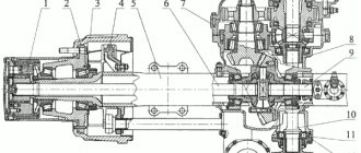
The structure of the rear axle of the GAZ-53A and GAZ-66 cars is shown in Fig.
1 and 2. To increase durability, a hypoid type main gear is installed in the bridges. The drive gear relative to the driven gear is shifted downwards by 32 mm. To prevent large deformations of the driven gear, the main gear is equipped with an adjustable stop. The main gear and differential are mounted in a separate gear housing, which is loosely inserted into the hole in the axle housing and secured with bolts.
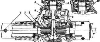
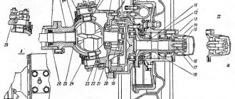
The rear axle gearboxes of the GAZ-53A and GAZ-66 vehicles differ only in the design of the differential. On the GAZ-53A car, a conventional bevel differential with four satellites is used, and on the GAZ-66 car, to increase cross-country ability, a self-locking cam differential is installed, the design of which is shown in Fig. 63. In the separator 28 there are 24 radial holes arranged in two rows in a checkerboard pattern, into which crackers 25 are installed. Between the rows of holes for crackers on the outer and inner surfaces of the separator, there are locking rings that prevent the crackers from rotating around their axes, and also hold them from falling out of the separator when assembling the differential. The outer sprocket 27 is freely installed in the hole of the cup 22, and the inner sprocket 30 is installed in the holes of the separator a and the outer sprocket.
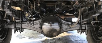
The rear axle housing of the GAZ-53A and GAZ-66 cars consists of two stamped halves, welded along the horizontal axis of the bridge. This design ensures ease of installation and dismantling of the unit. The wheel axles at the ends of the crankcase of the GAZ-53 car are butt welded, and on the crankcase of the GAZ-66 car they are attached to the crankcase using studs.
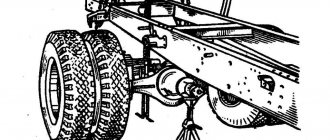
The GAZ 53 car has a driven rear axle, and a beam is installed on the front axle. Both axles are secured with springs, shock absorbers are present only on the front suspension. The rear axle of the “53rd” is equipped with a gable tire, that is, a total of four wheels are installed at the rear.
Finishing the cab of a GAZ 53 truck
Rear axle
The rear axle on a GAZ-53 is one of the most important components on which the performance of the vehicle depends. Therefore, it is necessary to periodically inspect the parts of the rear axle and make its adjustments.
The GAZ 53 rear axle includes the following parts:
- Housing (or crankcase). Stamped, is a welded structure. Outwardly, it resembles an elongated stocking with a thickening in the middle. In the center there is a wide hole for mounting the gearbox; on the back side of the hole, a stamped cap is welded to the crankcase. When installing the rear axle gearbox, the structure becomes sealed; a gasket (made of cardboard or paronite) is required between the gearbox and the crankcase for tightness;
- Gearbox assembly. It consists of its own separate housing, gears of the main pair (drive and driven), differential assembly;
Diagram of the rear axle and gearbox GAZ 53
8.2 liters of transmission oil is poured into the rear axle housing. A control plug is screwed onto the right side of the gearbox housing. After unscrewing the plug, check the oil level in the bridge; through the same hole, pour or top up oil to the required level. The bridge is considered filled when oil begins to flow back out of the control hole during filling.
Disassembled gearbox for gas 53
- Gear ratio – 6.83 (number of teeth on the driven gear – 41, on the drive gear – 6);
- The assembled weight of the bridge is 270 kg;
- The gears of the main pair are of the hypoid type;
- Differential – gear, conical type;
- Rear wheel track (distance from the center of the paired wheels of one side to the center of the other) – 1.69 m.
It should be noted that the rear axle of the GAZ 66 in its basic design is no different from the GAZ 53 axle, and the gear ratio is the same.
This is what the rear axle for GAZ 66 looks like
Description of work
The axle shaft of the GAZ-53 car is made of 40ХМА steel. The rear axle axle shaft is the link connecting the main gear to the drive wheel; it transmits torque. The axle shaft is completely unloaded - this means that it only perceives torque, which causes a twisting state in it. Based on the listed characteristics, the axle shaft is one of the most critical parts in the drive axle. Excessive torque can damage the part. Also, the natural aging of metal under variable loads also increases the likelihood of part failure. The axle shaft does not perceive a constant torque, but an alternating torque and varying in magnitude - this classifies the part as critical and imposes more stringent requirements on it. The main malfunction of the axle shaft is its twisting and ultimately breaking. If it breaks, it is not possible to repair the axle shaft; it is discarded. Along with serious faults that cannot be repaired, others also arise that can be corrected and prevented, such as bending, wear of splines, wear of the seat ring, wear of bolt holes. Such malfunctions can and must be eliminated, since the cost of repair is much lower than the cost of a new part.
In this work, a technology was developed to restore the functionality (repair) of the axle shaft of the GAZ-53A drive axle. Submerged arc surfacing followed by machining was chosen as a method for repairing splines. The alignment is corrected by straightening and then eliminating the runout.
Rear axle inspection
In order to inspect all the parts of the rear axle, you must first soak these parts in a washing solution. This does not apply to bearings. Next, the parts must be thoroughly washed and inspected. Those parts on which you find cracks must be replaced without fail.
This is what the rear axle gearbox looks like.
Its weight is 69 kg.
Now let's begin inspecting the drive and driven gears. This is where we look for wear or scoring. If there is even one flaw, it is better to immediately change the gear; there is no need to try to repair it. The effect will not last long.
After this, you can proceed to the bearing rings. Here they need to be inspected for scoring and uneven wear. Particular attention should be paid to the ends of the rollers.
Construction of the Gas 53 bridge.
To check that the nuts are screwed in, you need to install the bearing cap and tighten the nuts. If the nuts turn without any problems, then everything is fine. You should immediately inspect the end of the driveshaft flange, which is connected to the drive gear bearing. The end must be perfectly smooth. If it doesn't, then sand it down.
The oil passages on the bearing coupling must be periodically cleaned. Inspect it for damage, burrs, etc.
Make sure that the bearings fit snugly on all bearing surfaces, this will ensure that your differential will last for a long time. You should also check the runout of the driven gear. If the runout does not correspond to the norm, then look for the reason for this in the gear, which may have been deformed. Or maybe the differential box is damaged or the bearing is worn out.
Brief instructions:
- Search for suitable jobs in the search bar at the top center of the page or in the side navigation bar on the left.
- Evaluate the quality of the work using the content and screenshots of the drawings that are in the archive. To view screenshots, download the archive from the payment page.
- If the work suits you, choose a payment method (Yandex-money, Frikassa or Interkassa) or use your personal account and personal account, which you can top up there.
- Expect the archive password to be sent to your email. To speed up receiving your password, you must fill out the payment form correctly - indicate your email address.
- If you need it urgently, then contact us personally on WhatsApp or the phone number indicated in the header of the site.
Quick navigation to key questions:
- How to pay for the work?
- Discount system
- How to get a password for work?
- How will you understand that I paid for the work?
- How long will it take to get a password for a paid job?
- Mail: ,
The work has been moderated and corresponds to the topic
Front axle
The front axle on the GAZ 53 truck is a massive beam, which is the supporting basis for the entire front suspension. The beam has an I-section, its ends have eyes for installing rotary axles using a pin connection. The axles (steering knuckles), in turn, are connected to steering rods, through which the wheels turn. Bronze or brass bushings are pressed into the seats (eyes) under the pivots. The steering knuckles are mounted on the front wheel hub bearings; the bearings are filled with thick grease of the “litol” type.
Front axle malfunctions
Only one problem can happen to the beam itself - the seats for the pin bushings will be worn out. It is not easy to bend or break such a massive element. But first of all, the pins and the bushings themselves wear out.
Front axle drawing for GAZ 53
A sign of a front axle malfunction may be a knocking sound in the area of the front wheels. The knocking occurs due to increased play in the pivot joints.
It is not difficult to determine the defect - you need to hang one front wheel on a jack and rock it up and down. It is believed that if the play is more than 1.6 mm, the kingpins and bushings must be replaced. But how these millimeters are measured is not very clear. It’s just that if there is a noticeable gap, it’s time to repair the front axle. The wheel bearings on the front axle may be noisy. The defect of the front bearing is checked in the same way as on the rear axle - the wheel is hung up and rotated.
Spare parts for trucks
Full model range: GAZ-3307, 53, GAZ-3309, GAZ-66, 3308, 33081, 33086, GAZ-33104
GAZ-53 car and its main parameters
The GAZ-53 vehicle with a carrying capacity of 4 tons and drive to the rear axle (rear axle) is designed for transporting various materials and cargo on all types of roads.
The main components of GAZ-53 vehicles (engine, clutch, gearbox, cardan transmission, brakes, etc.), electrical equipment units, components and parts are unified.
Technical characteristics of the GAZ-53 car
Load capacity, kg - 4000 Maximum weight of a towed trailer with cargo, kg. — 4000 Vehicle weight in running order, kg — 3250
Overall dimensions of the GAZ-53 car, mm: - length - 6395 - width - 2380 - height (in the cabin without load) - 2220 Base, mm - 3700 Front wheel track (on the ground) - 1630 Rear wheel track - 1690 Lowest points (with full load): — drive axle housings — 265 — front axle — 347
Turning radius along the track of the outer front wheel, m - 8 Highest speed of a GAZ-53 car with a full load without a trailer (on a horizontal section of the road with an improved surface), km/h - 80-86 Control fuel consumption when measured in the summer for a run-in car GAZ-53, moving with a full load in fourth gear at a constant speed of 30-40 km/h, l / 100 km - 24
GAZ-53 engine Number of cylinders and their arrangement - 8, V-shaped Cylinder diameter, mm - 92 Piston stroke, mm - 80 Cylinder displacement, l - 4.25 Compression ratio (average value) - 6.7 Maximum power (limited regulator) at 3200 rpm, hp. — 115 Maximum torque at 2000 — 2500 rpm, kg/cm — 29 Cylinder operating order — 1—5—4—2—6—3—7—8
Transmission of the GAZ-53 car
Clutch GAZ-53 - Single disc, dry
GAZ-53 gearbox - Three-way, with synchronizers in third and fourth gears.
Transfer case - Has two gears: direct and reduction with a gear ratio of 1.982
Cardan transmission GAZ-53 - Open type, has cardan shafts with needle bearings. Main gear of drive axles - Conical, hypoid type, gear ratio 6.83
Differential - Gear, Cam, bevel, limited slip. Steering axles - Flanged, CV joint
Chassis of GAZ-53
Springs - Four longitudinal semi-elliptical, the ends are embedded in rubber supports.
The rear suspension of the GAZ-53 has additional springs.
Shock absorbers - Hydraulic, telescopic, double-acting. Installed on the front axle and both axles.
Steering GAZ-53
Steering mechanism type: Globoidal worm with three-ridge roller. Gear ratio - 20.5 (average) Power steering (power steering) GAZ-53 - Hydraulic.
Brake system of the GAZ-53 car
Foot brakes - Shoe brakes on four wheels. Foot brake drive - Hydraulic with hydraulic vacuum booster.
Handbrake - Central drum type. Location: On the transmission driven shaft.
Electrical equipment of the GAZ-53 car
Wiring system - Single-wire with connection of the negative terminal to ground Mains voltage, 6 Generator - G130-G, power 350 W Relay regulator - PP130 Battery - 6-ST-68-EM Starter - ST130-B with remote switching Ignition coil - B13 additional resistance Distributor breaker - P13-B Spark plugs - A11-U
Cabin GAZ-53 - Metal, double, two-door.
Dimensions of the GAZ-53 platform, mm:
— length — 3,740 — width — 2170
— side height — 680 Compressor — Single-cylinder air-cooled
Adjustment data of the GAZ-53 car
Gap between rocker arms and valves on a cold engine (temperature 15-20°C), mm - 0.25-0.30
It is allowed to set the gap at the outer valves of both rows (intake of the first and eighth, exhaust of the fourth and fifth cylinders), mm - 0.15-0.20
Gap between spark plug electrodes, mm - 0.8-0.9
Gap in the breaker, mm - 0.3—0.4
Free travel of the clutch pedal, mm - 32-42/35-45
Free play of the brake pedal, mm - 8-13
Refueling capacities and volumes of the GAZ-53 car (l)
Fuel tanks (capacity) - 200 Gearbox housing - 3.0 Gearbox housing with power take-off - 4.2 Transfer case housing - 1.5 Rear axle housing - 8.2 Front axle housing - 7.7 Steering gear housing - 0.5 Shock absorbers (each separately) - 0.41 Winch gear housing - 0.8 Power steering - 1.8 Hydraulic foot brake drive system - 0.76
Dismantling of rear axle gearboxes of GAZ-53A and GAZ-66 cars
1. Unscrew the oil scraper plug and remove the locking plate.
2. Remove the tube, spring, plate from the oil channel.
3. Unscrew the driven gear stop adjusting screw.
4. Remove the differential locking plates and bearing caps.
5. Remove the differential bearing outer races and their adjusting nuts.
6. Remove the differential assembly from the crankcase.
7. Remove the drive gear shaft assembly from the gearbox housing (Fig. 2).
8. Remove the adjusting shims from the crankcase neck.
9. Remove the driveshaft flange, front differential cover and gasket.
10. Remove the bearing coupling along with the inner race of the front roller bearing.
The content of the work
INTRODUCTION 1 DESCRIPTION OF THE PART 2 OPERATING CONDITIONS OF THE HALF AXLE AND ITS MAIN DEFECTS 3 CHOOSING A RATIONAL METHOD OF RESTORATION 4 DEVELOPMENT OF A ROUTE AND TECHNOLOGICAL MAP 5 DEVELOPMENT OF OPERATIONAL CHARTS FOR RESTORING HALF AXLE DEFECTS 5.1 General issues of surfacing under a layer of flux 5.2 Calculation of surfacing modes 6 RATING OF SURFACING OPERATIONS AND CALCULATION OF TIME STANDARDS FOR REMOVAL OF THE DEFECT. 7 COST EFFECTIVENESS OF RESTORATION 8 CONCLUSION 9 REFERENCES