To monitor the systems, the GAZ car is equipped with an instrument cluster in which control devices are installed: voltage indicator, tachometer, speedometer, engine temperature indicator, oil pressure indicator, fuel level indicator and signaling devices. The connection of the instrument cluster contacts is shown in the electrical diagrams below, and the location of the electrical connectors can be seen in the photographs. The information is provided as a guide to troubleshooting and replacing the instrument panel yourself.
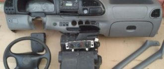
Installing and removing the torpedo
The instrument panel is only part of the euro kit for the Gazelle business.
Gazelle instrument panel lighting
In some cases, for example, to repair the heating system, it is necessary to completely dismantle the torpedo. This process is not the easiest, since you need to know from which side to approach such an issue. In fact, the panel can be removed in just half an hour. To do this you need the following:
- Use a Phillips screwdriver to unscrew the 3 upholstery fasteners.
- Carefully remove all upholstery pads so as not to damage anything.
- We dismantle the steering column with all connections to it.
- We remove the instrument panel by disconnecting all wires.
- Next you will need to turn off the interior lighting and rear fog lights. Then we turn off the electric headlight adjustment.
- We arm ourselves with keys 7 and 8, get to the bolted fastening of the choke cable. Hold it with one key and unscrew it with the other.
- We unscrew the screw of the cable sheath and disconnect the cable from the Gazelle carburetor.
- We turn off the hazard warning lights and cigarette lighter plugs.
- Again, take a screwdriver and tighten 2 screws near the stove control.
- We unscrew all the screw fastenings of the panel, there are 10 of them in total. Lightly pull the panel towards you so that it comes off the installation site. Now you can disconnect the air duct hoses from the deflectors.
- We take out the damper from the carburetor. We remove the panel. We turn off the right and left air ducts of the stove.
- We remove the torpedo. You will need an assistant here, since the torpedo is very heavy.
- We twist the fastenings of the torpedo lining and remove the lining itself.
- Installation is carried out in reverse order.
First option
Early cars were equipped with a mechanical speedometer driven by a flexible shaft of the GV 310 model. The flexible shaft was installed at one end on the gearbox housing, and the other was attached to the speedometer housing. The drive was carried out from a helical gear mounted on the secondary shaft in the gearbox. It is located closer to the rear shaft bearing.
The speed sensor of the Gazelle in this case was the speed measuring device itself. The flexible shaft rotated the magnetic disk, creating a magnetic field. Its intensity depended on the shaft rotation speed. This field turned the spring-loaded needle. The Gazelle speedometer drive cable is shown in the photo.
Drive maintenance consisted of timely lubrication of rotating components and control over the route of the cable. The radii of cable bends should not be more than 150 mm.
DIY wiring installation, video, photo
Removing and installing the ignition switch on VAZ 2108, VAZ 2109, VAZ 21099 cars
After restyling in 2003 and 2010, the popular truck in Russia received a new name - “Gazelle-Business”. But not only did the car receive a prefix to its name and a modified cladding - more than 20 components were modified, and in total the automaker made 130 changes to the design, including a redesigned electrical circuit.
If we compare the first-born, which was released back in 1994, and the new product, the alterations turned out to be significant. The maintenance experience accumulated over the years of operation allowed us to formulate tasks for designers and engineers, which were implemented in the new model.
Restyled Gazelle Business
Radical changes to the electrical circuit
In particular, the electrical wiring of the Gazelle 3302 has changed significantly due to the appearance of long-awaited elements:
- Diesel engine;
- ABS in the brake drive;
- Air conditioning;
- Cruise control.
Diesel Gazelle
Factory wiring diagram Gazelle 3302
With the advent of long-awaited diesel engines in the line of power units, in particular, a Cummins engine made in the USA, the electrical equipment layout has also changed.
Although the diesel engine is free of the ignition system traditional for gasoline engines, its design contains a lot of other electrical components, among which the main ones are:
- Fuel pump control unit;
- Exhaust gas afterburning system control unit.
Caution: using non-standard firmware for the engine control unit is not recommended, since the factory settings are designed to balance the different torque of the engine and gearbox.
Accordingly, the wiring of the Gazelle Business has also undergone changes (compared to the wiring diagram of the Gazelle with the 402 engine), since in the diesel version the following is installed:
- more powerful battery,
- new starter with improved characteristics;
- high performance generator;
The installation of energy-intensive equipment led to an increase in the load on the on-board network, which also required alteration of the Gazelle's electrical wiring diagram. Naturally, the automaker began shipping electrical wiring kits corresponding to different power units to service points and auto parts stores.
Sanden air conditioners
With the advent of air conditioners from the Japanese company Sanden, the electrical wiring on the Gazelle 3302 also underwent changes. In addition to additional consumers of the current source in the car interior (control unit), power was required in the engine compartment for both the electric fan and the pump.
Japanese Sanden air conditioner for Gazelle
Brake system
ABS, a system that prevents wheel locking during braking, also appeared on Gazelle Business for the first time.
The automaker began installing products from the German company Bosch in the brake drive:
- master brake cylinder;
- vacuum brake booster;
For reference: Preference was given to a 4-channel system with separate adjustment of the braking torque of each wheel.
Since 2011, ABS has become the basic equipment of minibuses intended for transporting passengers.
Additional components
The Gazelle business wiring diagram has also undergone modification due to the appearance of:
- components and parts from ZF and Sachs in the clutch drive;
- power steering from ZF Lenksysteme;
- electrically heated exterior mirrors;
- a different front panel with a new instrument cluster;
- audio systems from Blaupunkt;
- updated cabin heater control unit.
Control unit for Blaupunkt audio system and air conditioning in Gazelle Business
In addition, cruise control of the Gazelle-Business family appeared as an option for the version with a power unit from Cummins, which also required changes to the electrical circuit of the car.
Conclusions: having subjected the Gazelle Business cars to modernization, the automaker has seriously improved the electrical wiring, for example, compared to the model with the 406 engine. That is why when replacing it or replacing its components, you should be guided by the manufacturer's electrical diagram.
Where to post
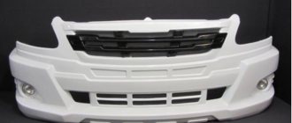
We need to start by choosing the place where our new foglights will be located. Traditionally, either a car bumper or a cab roof is used for these purposes. However, with the second option there may be difficulties in coordinating with traffic rules.
Note! According to these standards, the use of the roof is permitted for vehicles with all-wheel drive or in difficult operating conditions - dirt roads, potholes, etc.
Additionally, you need to know other requirements of the traffic police rules.
So, the installation of Gazelle fog lights must meet the following standards:
- the light flow should not be greater than that from the main light source of the car;
- the headlights must be installed so that they are parallel to the axis of symmetry of the car;
- the height must be at least 25 cm, and fog lights cannot protrude from the side of the vehicle by more than 40 cm.
Bumper mounting kit
Among other nuances that can be caused by installing fog lights on a Gazelle, you should pay attention to the shape of the products, as they can be rectangular, square, oval, etc. Place them in the places recommended by the manufacturer.
If this does not work, then you can cut holes in the existing bumper or buy a new one, specially prepared for this. The price of purchasing a new bumper may not be acceptable for every Gazelle owner, so we will further discuss how to do this without extra costs.
Pinout of an old-style gazelle instrument panel buy
Removing and installing EUR Priors
Connect to the pink wire with a red stripe. 9 - oil pressure indicator. At 382.3801, run a wire to the sensor (you need a VAZ-2106 tee) from GAZ under the ZMZ-406 engine.
With 385.3801, if you install a sensor, it will squeak about low pressure at idle, so a sensor is not needed, you need to connect the wire from the instrument panel to ground through a resistor, select it experimentally. 10 - emergency oil pressure indicator. Connect to the gray wire with a blue stripe. 11 - engine overheat indicator. Can be connected to overheat sensor TM-111-02. The sensor itself must be in contact with the coolant. 12 is the coolant temperature indicator. Connect to the green wire with a white stripe. The indicator will exaggerate the readings, you can connect a resistor to the wire gap and select it experimentally. 13 - indicator for closing the carburetor air damper.
How to wind up the speedometer
GAZelle cars were equipped with speedometers of several designs:
- with mechanical drive of all elements;
- with electronic drive speed indicator and mechanical odometer;
- electronic version with LCD screen.
Depending on the type of construction, different mileage adjustment techniques are used. If the owner is not confident in his abilities and knowledge, it is recommended to contact workshops that provide such a service.
On early GAZelle cars equipped with a mechanical speed meter, adjustment is carried out by rotating the cable from the electric motor. You can wind up a GAZelle Business with early versions of electromechanical meters using a motor from a computer fan. Power is supplied from the cigarette lighter socket, a free wire with green or yellow insulation is connected to the block (to the green conductor) located above the brake pedal. After turning on the ignition, winding begins.
There are devices mounted in the cigarette lighter socket. The signal wire is connected to the instrument cluster. The device is equipped with a potentiometer that allows you to change the speed of mileage adjustment.
You can make a winding for the speedometer yourself if you know the basics of electronics and circuit design. Such a unit will work on GAZelle-3302 cars equipped with an electromechanical speedometer. The homemade design is based on the 1006VI1 microcircuit; ceramic capacitors and resistors are used. To protect the device from erroneous connection, a diode type KD521, rated for a current of 1A, is used. The device must be insulated from moisture using insulating tape.
Principle of operation
The algorithm of action for all panels is the same. Each light bulb and arrow interacts with a specific element. So, the readings of both speed and mileage come from the sensor that is screwed onto the box. Engine information comes from the crankshaft sensor. And the voltage data comes from the generator terminals. What is noteworthy: if you do not connect the voltage contact, the car will not charge even with a working generator. This problem is accompanied by a red battery light on the panel. If it lights up, it means there has been a break and the wire does not fit into the connector of the device. As for oil pressure and coolant temperature, this information comes through the terminals from the corresponding sensors.
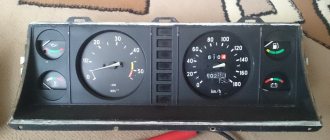
Are there any problems associated with the above shields? Unfortunately, owners are faced with the problem of a malfunctioning device. This happens least often with the very first panel, the old model. It works like a clock. The Riga panel may not accurately provide information about the oil pressure level. Also, the speedometer often malfunctions here. Along with this, the odometer refuses to work. But most of the complaints, surprisingly, are caused by the new instrument panel of the Gazelle Next and Business.
Thus, the most common malfunction is the kilometer reset (and total) at a mileage of 60 thousand kilometers. Because of this, it is impossible to accurately control the passage of maintenance and a number of other repair operations. But that is not all. The daily mileage is also reset to zero - reviews say. This happens if the voltage in the network is less than 11.5 Volts. Also, the data is erased if the terminals are removed from the battery.
The new Gazelle instrument panel does not work even when installed in an old Gazelle. It needs to be mounted correctly - simply switching the pads with contacts will not work. For successful installation, you need a pinout of the Gazelle Business instrument panel.
Among other malfunctions, it is worth noting that the speedometer and tachometer needles are stuck in one position. Most owners begin to panic and completely disassemble the shield. But you don't need to do this. The problem lies in insufficient contact of the connectors.
To install the panel, you must remove the old shield. To do this, you need to dismantle the steering wheel using a special puller and unscrew a couple of screws of the decorative lining of the dashboard. You should also unscrew the bolts securing the tidy itself.
To do this you will need a 8" head. After this, you can remove the old panel and put a new one in its place. But as we said earlier, simply switching the connectors will not work. You need a pinout for the Gazelle Business instrument panel. There are four pads in total - XP1, 2, 3 and 4. Let's look at how to connect each:
- XP1. The first, fifth, sixth, seventh contacts are connected to ground. As for the rest, they connect to the sensor signals. The first contact is the air damper closing relay, the third is the DTOZH, the ninth and eleventh are the oil pressure and fuel level sensors in the tank, respectively. The remaining contacts are “Reserve”. We do not touch them and do not connect anything to them.
- XP2. Contacts number two, four, nine are connected to ground. The “plus” terminals are all from the fifth to the thirteenth.
- HRZ. Terminals two and thirteen are connected to the +12V positive contact. The first, eighth and twelfth terminals are connected to ground. The sixth connector is the speedometer speed sensor, the ninth is the ignition coil, the eleventh goes to the engine control unit.
- XP4. Here, almost all contacts need to be connected to ground. This applies to connectors from the first to the seventh inclusive. Only the sensor for the presence of water in the fuel filter (if there is one) and the glow plug switch are positive. These are connectors number eight and nine respectively.
By the way, if the car does not have an ABS and EBD system, the outputs to these sensors must be plugged. How? It is enough to connect them to ground.
So, we found out what the Gazelle instrument panel is, what types it comes in and how it is connected.
Diagnostics
If the speed control unit fails, then you need to understand which of the elements of the entire circuit has failed. The control of the Gazelle stove is electronic, and all drives are electric.
- To begin with, with the engine turned off, we try to turn the temperature regulator. When you turn it, you should hear clicks from the gear motor. If there are no clicks, then you need to check the power in the block that comes to the tap opening motor. This can be done using a test lamp or a multimeter.
- If the fan speed controller does not work, you need to check its operation in all positions. If it does not work in all positions except the last one, then the reason is a faulty rheostat. If operation is not heard in any of the positions, then you need to check the power supply to the fan block. If power comes in, then it is broken.
- If the stove adjustment works correctly, but the display does not light up, then the display itself or the backlight is faulty.
Whether to install a new dashboard on a Gazelle or not - that is the question
The only drawback is the weak backlight, which is almost invisible at night.
It is recommended to install LED backlighting of the instruments along the entire perimeter of the panel (the author of the video is Vodila Chelyabinsk). The Gazelle has 20 indicators installed, indicating that one of the components or sensors of the car is not working. If the “Stop” light comes on along with one of the icons ", it is advisable to eliminate the malfunction before driving. The dashboard, using indicators, displays information about the condition of the main components and assemblies of the vehicle. A detailed description of the purpose of each of them can be found in the installation and operating instructions. After replacing the device, the following malfunctions are possible:
- either part of the instruments or the entire panel does not work; the arrows on the instruments stop; incorrect sensor readings.
You can solve the problem by doing the following: First you need
Possible problems
Even if you change the panel to a Gazelle, you won’t be able to get rid of all the problems. Quite often problems occur after replacement. Here are the most common ones:
- individual sensors or the entire panel stops working;
- instrument readings “freeze”;
- The sensors lie, the indicators are incorrect.
Most drivers panic and then take the panel apart, which only makes things worse. Here are some solutions for most panels:
- The first thing you should always do if such devices malfunction is to check the wire contacts. A break or breakdown can cause a malfunction. You should also inspect the food.
Pinout and instrument cluster on the Gazelle panel
Since the electronic system is not improved by replacing the panel, and the devices are more demanding, problems occur with the electronics. Replacing the wiring and fuses most often solves the problem. Generally, reviews about the operation of the instrument panel are favorable, but on some older car models there are a number of problems that can only be solved by installing original instruments.
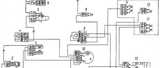
GAZelle Business instrument panel harness diagram.
footrest lamp; 24 – block with lower interior wiring harness; 25 — additional heater fan; 26 — additional resistor (0.85 Ohm, 35 W); 27 – reverse light switch; 28 — speed sensor; 29 — parking brake switch; 30 — left door block; 32 — left rear view mirror; 33 — right interior lamp; 34 — front interior lamp; 35, 36 — left lampshades; 37 — relay and fuse block; 38 — mirror heating relay; 39 — low beam relay; 40 — high beam relay; 41 — sound signal relay; 42 — heater pump relay; 43 — windshield wiper relay; 44 — diagnostic connector; 45 - fuses; 46 — lighting control unit; 47 — heating and ventilation system control unit; 48 — instrument cluster; 49 – micro-reducer for driving the windshield blower damper and foot area; 50 — micro-reducer for driving the panel deflector flaps
Possible malfunctions and ways to eliminate them
Incorrect operation of the indicators on the instrument panel is usually associated with problems with the system sensors. It is with him that the system receives all the information. Before you begin repairing the panel, you should check whether the sensors themselves are operational. If everything is fine with them, but the data is not displayed or is displayed with distortions, the problem may also be hidden in the wiring.
Another common problem is the burnout of individual instrument bulbs. They are quite easy to replace at home. True, you may have problems finding new parts, since car production has long been discontinued. But you can find suitable ones in any good radio electronics store or auto shop.
From the video below you can learn how to replace light bulbs (the author of the video is NONAvto).
Repair
Repair of the control unit will directly depend on the cause of the malfunction:
- If the power check shows that there is no “+” on the gear motor, then there is a malfunction in the heater control system. It needs to be dismantled and either repaired or replaced with a new one. For repairs, it is better to use the services of specialists, and if you have experience in this work, you can try to solve the problem yourself. To dismantle it is necessary: remove the top drawer for documents; unscrew the front panel (two screws on top and two on bottom); remove the decorative trim; pull out the entire panel so that all terminals can be numbered; disconnect the terminals; then take out the control element itself. Then reassemble everything in reverse order.
- To replace the resistor, you need to either remove the entire dashboard, or cut a hole under the box for documents, after first removing the box itself. To replace the fan, it is necessary to dismantle the entire instrument panel along with the stove. Then disconnect the stove from the dashboard, “halve” it and remove the resistor. If there is no power to the fan block, then the reason must be sought in the heater control system. To do this, you need to check it with a multimeter. Pinout of contacts of the Gazelle Business heater control unit:
- reserve;
- motor-gearbox (MR) feedback, heat-cold;
- access to the BRS;
- reserve;
- 5V, power supply for external temperature sensor;
- tap closing signal;
- tap opening signal;
- coolant heating sensor input;
- external temperature input;
- interior temperature sensor input;
- reserve;
- external temperature sensor housing;
- feedback, MR, glass - legs;
- MP heat – cold “+”;
- MP heat – cold “-”;
- MP recirculation “+”;
- MP recirculation “-”;
- MR glass – chest “+”;
- MR glass – chest “-”;
- MR glass – legs “+”;
- MR glass – legs “-”;
- feedback MR glass – legs 1;
- output of the heated glass and mirrors relay “+”;
- air conditioning relay output “-”;
- frame;
- feedback MR heat – cold 2;
- on-board network.
- To repair the display, you need to dismantle the entire heater adjustment element (as described in point No. 1) and repair or replace the entire assembly unit. If you repair it yourself, you can change the handle illumination diodes to a different color or change the brightness.
The stove is a very important element in a car. It affects not only the driver’s comfort, but also the safety of driving (since if the windows fog up in cold weather, driving becomes difficult). And it’s better to do all the work in a warm garage or parking lot than to do it on the road.
Panel purpose
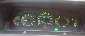
The instrument panel performs one function - informational. In a small area in the dashboard of the car, all the instruments with indicators about the car’s performance are located, this is both good and not very good. While the driver is looking for the indicator, the speed indicator, he is distracted from the road, creating conditions for an emergency situation. However, most Gazelle users eventually get used to the appearance of the panel and intuitively examine one or another section of it to obtain information.
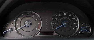
The standard panel on most modifications of the Gazelle looks like 3-5 round dials surrounded by several signaling devices. The main gauges—the speedometer and tachometer—are large.
The speedometer is always located in the center, since it is the main device that the driver focuses on. The three largest devices most often include the coolant temperature sensor. The remaining dials indicate either the amount of gasoline, or the battery charge, and less often, the amount of oil. All the indicators that the driver needs can also look like warning lights. Their indicators light up from time to time. The devices are placed compactly and do not interfere with each other.
. 2705, 33021 “”
. 9.51. : 1 , 2 5-54, 3
, p. 9.51. 5-54 10 3, 6+1 200250. :
. 9.52. : 1, 2, 3, R1 -0.25-10, V1 102
. 9.53. : 1 ; 2 ; 3 5-54
, . 9.53. 5-54 1 6 , 122 200250 . 240 1000+100 -1, 960 4000 -1.
P. 9.54. : 1 ; 2 ; 3 1, 4, R1 -2-330, R2 -2-120, R -2-15
, . 9.54. RI, 0, R2 1/2, R3. . : 330+15, 11+5. 70 ( ) 118+10 .
25 14001900 , 80 200270 .
. 9.55. : 1 ; 2 ; 3 1 ; R1 -2-250
. 9.56. : 1 ; 2 ; 3 1 ; 4 ; R1 -2-180 ; R2 -2-60
, . 9.56. R1 1.5 /2, R2 4.5 /2. .
290330 , 1,5 /2 170200 , 4,5 /2 5080 .
30 I (5-48). , . 12 14 +0.4 .
Old style gazelle instrument panel pinout
When the pressure in the engine lubrication system drops from 0.4-0.8 kg/cm2, the warning light in the instrument cluster lights up.
We recommend reading: Should an organization retain its minimum wage debt?
The alarm works with a sensor type MM111-B.
If there is no pressure in the system, the sensor membrane bends away from the contacts and the lamp lights up, and if there is pressure, the membrane bends in the opposite direction, opens the contacts and the lamp goes out. Voltage indicator Ratiometric type voltage indicator, with fixed windings.
The voltage indicator device is similar to the fuel level indicator.
Rice. 9.57. Electrical circuit for checking the voltage indicator: 1 - adjustable direct current source, 2 - control voltmeter, 3 - plug-in connector HRZ of the instrument cluster. To check the voltage indicator, it is necessary to assemble the electrical circuit shown in Fig.
9.57. In addition, the dashboard contains dials for charging the battery and the amount of gasoline.
Block in the cabin
It is located under the panel on the left side, behind the protective cover.
Old style block
Scheme
Description
Upper block
| 1 | 16A Electric heater motor, electric heating pump (vehicles with two rows of seats) |
| 2 | 8A Reserve for the electric motor of the additional heater (vehicles with two rows of seats), relay for the electric fan of the engine cooling system (installed on parts of vehicles) |
| 3 | 8A Direction indicators |
| 4 | 8A Instrument cluster, parking brake warning lamp switch, EPH system, windshield wiper relay, reverse light, diagnostic warning lamp |
| 5 | 8A Hazard alarm |
| 6 | 8A Buzzer and lamp for onboard platform lighting, brake signal |
| 7 | 8A Radio equipment, remote battery switch, |
| 8 | 8A Electric motors for windshield wiper and washer |
| 9 | 16A Cigarette lighter , horn, portable lamp sockets |
| 10 | 16A Reserve |
Bottom block
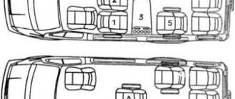
| 1 | 16A Fog lights |
| 2 | 8A Cabin lighting lamp(s), cargo compartment lamp (GAZ-2705, -27057), engine compartment lamp, lamps for the left row of passenger compartment seats and footrest lighting |
| 3 | 8A Instrument cluster illumination |
| 4 | 8A Rear fog lights |
| 5 | 8A Right front side light, left rear side light, license plate lights, side light warning lamp |
| 6 | 8A Left front side light, right rear side light, fog light relay |
| 7 | 8A Left headlight (low beam), electric headlight range control |
| 8 | 8A Right headlight (low beam), electric headlight range control |
| 9 | 16A Left headlight (high beam), high beam indicator lamp |
| 10 | 16A Right headlight (high beam) |
New sample block
Scheme
Designation
Upper block
| 1 | 25A Engine control system (ZMZ-40522, UMZ-4216) |
| 2 | 15A Hazard warning lights |
| 3 | 15A Ground switch (on buses), radio |
| 4 | 10A Electric motors for windshield wiper and washer, right row of bus interior lamps |
| 5 | 10A Headlight relay, ABS (for buses) |
| 6 | 10A Brake lights |
| 7 | 20A Horns, cigarette lighter |
| 8 | 20A Heater motor, additional heater electric pump |
| 9 | 15A Additional heater motor |
| 10 | 10A Instrument cluster, reverse light, speed sensor, parking brake warning light switch, wiper relay |
| 11 | 5A Oxygen concentration sensor (ZMZ-40522, UMZ-4216) |
| 12 | 15A Engine management system and fuel pump |
| 13 | 10A Direction indicators |
| 1 | 25A Reserve |
| 2 | 15A Main beam of the right headlight, high beam indicator |
| 3 | 15A High beam left headlight |
| 4 | 10A Low beam right headlight |
| 5 | 10A Low beam left headlight |
| 6 | 10A Fog lights, fog light indicator |
| 7 | 20A Reserve |
| 8 | 20A Reserve |
| 9 | 15A Cabin lamp, lampshade (or lampshades on GAZ-2705, -27057 vehicles with one row of seats) of the cargo compartment, lampshade for lighting the bus steps, engine compartment lamp, left row of lampshades for lighting the passenger compartment of the bus |
| 10 | 10A Illumination of instruments, switches and cigarette lighter |
| 11 | 5A Reserve |
| 12 | 15A Side light on the right side, headlight range control, glove compartment lamp |
| 13 | 10A Side light on the left side, side light indicator, license plate light |
Speed sensor is interchangeable 534.3843 GAZ-3110, UAZ-3160, UAZ-3165
Match by number
Gas 3423843 Speed sensor GAZ, UAZ injector (round connector) 6 imp. (534.3843) (GAS) G-PART
zommer 3423843 Speed sensor 406 dv.3110,3310,UAZ (6/imp round (ZOMMER/3423843)
Soate 3423843 Speed sensor GAZ-3110, GAZ-3302, 6 imp. round connector with wire
Pekar 3423843 Speed sensor (6-imp, O-fork, not bad) G, Euro-3 CUMMINS 2.8 “Pekar”
China 3423843 Speed sensor GAZ-3110, GAZelle (round connector/6 imp)
Energomash 3423843 Speed sensor 6 pulse round connector
AvtoVAZ 3423843 Speedometer sensor 342.3843 GAZ, UAZ (49.3843)
Manover 3423843 Speed sensor 6-pulse (round connector with wire) GAZ-3110, UAZ-Patriot analogue OEM NO 342.
AVAR 3423843 Speed sensor 5-speed gearbox 6-imp. circular connector “EMERGENCY”
Cartronic 3423843 Speed sensor for GAZ 3302, 3110 doors. 406 (6 imp. round) CARTRONIC
Electrics 3423843 Speedometer sensor 342.3843 3110 (round connector, 6 pulse) (speed meter)
Kursk 3423843 SPEED SENSOR GAZ-3110 6 IMP. SCHETMASH
UAZ 3423843 Speed sensor (speedometer drive) GAZ-3102, 3110, 2217, 2705, 2752, 3302; UAZ-3160 ** “PEKAR”
Russia 3423843 speed sensor G-3110,U-3160.65 (6 imp. round size) art. 342.3843 (Schetmash, Kursk)
ZMZ 3423843 Speed sensor GAZ, UAZ/6 imp./round connector/534.3843/35172.03/Energomash/
Kaluga 3423843 Speed sensor 5-speed gearbox 6-imp. circular connector “Kaluga”, pcs.
Diagram and contacts of the Gazelle instrument cluster
XP1 connector
1 Coolant temperature sensor 2 Emergency coolant temperature selection 3 Emergency low engine oil pressure 4 Oil pressure sensor 5 Fuel level sensor 6 ———- 7 ———- 8 Open bus doors 9 ———- 10 Open interior doors, hood or trunk 11 ——— 12 ——— 13 Malfunction of the electronic brake force control (EBD)
XP2 connector
1 Battery 2 Right side turn signal lamps on 3 Left side turn signal lamps on 4 Parking brake on 5 High beams on 6 Front fog lights on 7 Gearbox illumination 8 Side lights on 9 Rear fog lights on 10 ——— 11 Center differential lock on 12 Downshift 13 Type of oil pressure sensor
XP3 connector
1 Housing for analog signals 2 Ignition 3 Housing 4 High-voltage tachometer input 5 Low-voltage tachometer input 6 Low beam headlights on 7 Low battery 8 Ignition 9 Low brake fluid level 10 Speed sensor 11 Speedometer output to on-board computer 12 Heated rear window on 13 Anti-lock brake malfunction brake systems (ABS)
XP4 connector
1 Diagnostic indicator (-) 2 Diagnostic indicator (+) and activation of engine preheating (+) 3 Wear of brake linings 4 Activation of engine preheating (-) 5 ————- 6 ————- 7 ————- 8 ————- 9 ————— 10 ————- 11 Windshield washer fluid level low 12 Coolant level low 13 Engine oil level low
The pinout of the device combinations of the 38.3801 family in various versions is shown in the table:
Detailed description of icons
Details about instrument combinations, decoding of symbols and pictograms are described in the GAZelle operating instructions.
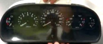
The panel is a combination of instruments with sound and signal indication. The main meters that the driver focuses on are the speedometer and tachometer, located on either side of the signal sensors. The speedometer indicates the speed of the vehicle. Its scale ranges from 0 to 200 km/h. The tachometer shows the crankshaft rotation speed of the power unit per minute with a scale of 0-6.
On the left side of the speedometer there is a device that determines the amount of fuel in the fuel tank. Nearby is the “Reset” button, when clicked, the daily mileage readings are reset to zero. Mileage parameters can be read on the digital odometer, with the upper numbers indicating the total value, the lower ones indicating the daily value.
To the right of the tachometer is the coolant temperature indicator. The arrow moving into the red sector means the engine is overheating. The motor runs until the alarm high temperature signal is triggered.
In the lower right corner there is a “Mode” button that turns on the ignition. Signal sensors are installed in the center of the panel.
Flashing red:
- STOP indicator, when activated, further movement is prohibited until the problems in the car are resolved;
- indicator of lack of battery charging, which operates when the ignition is turned on until the engine starts;
- indicator of low oil pressure in the engine;
- minimum fluid level sensor in the brake system hydraulic drive reservoir;
- engaging the parking brake.
The following are lit in green:
- left and right direction indicators;
- side light switch;
- Low beam headlight switch indicator.
Sensors flashing orange are responsible for turning on the rear fog lights, as well as for malfunctions of the anti-lock braking system and engine control mechanism. The high beam switch is blue.
In addition to the color display, an audible warning in the form of a characteristic signal has been developed on the instrument panel. It occurs in the following cases:
- when the fuel level drops to a minimum;
- when the engine temperature rises to 105° or more;
- when the handbrake is released and the car is moving at a speed of 2 km/h.
The disadvantage of the new panel is that it is difficult to install. The problem is solved this way: the pinout diagram is included in the package, you just need to add a few terminals, change the contacts so that all systems and components work correctly, connect LED lighting inside the devices and around the perimeter of the panel for better visualization.
Installation instructions
For installation, in addition to the GAZ Volga dashboard itself, you will also need car wires and heat shrink. And several terminals for pins XP 1, XP 2, XP 3, XP 4. You can find everything you need at an auto parts store. The part itself must be accompanied by instructions for its assembly.
To replace the old shield with a new one, you should follow these steps.
- First, remove the 4 screws that secure the panel. Also, 6 screws of the column casing, remove it.
- Now unscrew the 4 screws that secure the shield itself.
- After disconnecting the 5 XP connectors, remove the part.
- Now you need to connect the wiring using the instructions for your specific panel model and XP terminals.
- Turn off the ABS and EBD indicators if your car does not have such devices.
- Install in the reverse order of dismantling.