Ural motorcycle clutch device
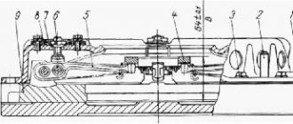
The motorcycles of the Irbit Motorcycle Plant use a dry double-disc clutch (Fig. 1).
The drive disks (pressure, intermediate, thrust) are made of steel. The working surfaces of all disks are polished. In the center of the pressure plate there is a square hole, and in front there are recesses for springs. The pressure and thrust discs are centered on the flywheel pins and can move freely along them in the axial direction. The thrust disk is attached to the fingers with countersunk screws. The screws are locked by punching the metal of the disk into the screw slot. To properly assemble the Ural motorcycle clutch and maintain the balance of the flywheel and clutch, marks are applied with a core on the discs and on the annular edge of the flywheel, which are aligned during assembly. Friction linings are molded to the steel driven disks and splined hubs are riveted to transmit torque. The clutch release rod on the Ural motorcycle has a square shank, which prevents the rod from turning in the pressure plate. The rod together with the tip rotates relative to the slider in the thrust bearing. The slider, due to the action of the lever, moves forward in the axial direction and, through the bearing, tip and rod, moves the clutch pressure plate and separates the disks, as a result of which the transmission of torque stops. If the force is removed from the lever, then under the action of springs the disks move back, returning the rod, tip, bearing, and slider to their original position.
The disks are pressed against each other by springs, and friction forces arise, which transmit torque.
If the lever is released smoothly, the discs are pressed against each other gradually, the friction forces increase smoothly, the torque will increase gradually, due to which the Ural motorcycle moves off smoothly.
If the torque exceeds the calculated value, for example due to the inertia of the flywheel at high speeds, then when the engine and transmission are rigidly connected, destruction of parts may occur. If there is a clutch, if the calculated value of the torque is exceeded, the friction forces of the discs are not enough to transmit such a torque, the discs slip relative to each other, protecting the parts from destruction.
The clutch is controlled by a lever on the left side of the steering wheel. When you press the lever, the force is transmitted through a flexible cable (Bowden cable) to a lever on the gearbox, which acts on the slider and disengages the clutch.
Since the clutch parts wear out during operation, the position of the clutch lever on the gearbox changes - the free play of the lever increases, and clutch control is disrupted. To regulate the correct engagement and disengagement of the clutch on the Ural motorcycle, there are adjusting screws on the cable, which are used to achieve such a position so that when you press the clutch release lever on the steering wheel before the discs begin to separate, the free play of the lever is 5-8 mm. Free play is measured at a distance of ¾ of the lever length from the axis of rotation.
To check the free play, the lever on the gearbox must be moved to the rearmost position, while the lever on the steering wheel will turn all the way into the bracket (clockwise). Next, you need to move the lever on the steering wheel towards you. At first, the lever should move almost without force, and at the moment the clutch begins to disengage, with force. The distance by which the lever on the steering wheel moves before the force begins to increase is called free play. If there is no free play, the clutch control parts will prevent the clutch discs from pressing tightly. In this case, the friction forces between the disks will be small, which will lead to incomplete transmission of torque. In this case, the clutch “slips” and the speed of the Ural motorcycle does not increase with increasing engine speed.
The reason for clutch slipping on a Ural motorcycle can also be oil from the engine or gearbox getting on the discs when the seals are destroyed, since this reduces the coefficient of friction of the discs and the clutch slips. As a temporary measure to eliminate this defect, it can be recommended to pour gasoline into the flywheel cavity through the inspection window to install the ignition and turn the flywheel using the kickstarter, simultaneously turning the clutch on and off. This operation must be performed quickly to avoid gasoline leaking out of the flywheel cavity. However, at the first opportunity, it is necessary to eliminate the cause of oil getting on the discs.
Sometimes, even with proper adjustment, the clutch “leads,” which is caused by warping of the discs, which occurs when the clutch overheats. This occurs during prolonged operation with the clutch slipping, for example, when driving at very low speeds, during prolonged driving in difficult road conditions (mud, sand, snow, potholes), when you have to use the clutch frequently. It is advisable to avoid driving in such conditions, since not only the clutch, but also the engine may overheat.
TRUCKS GAZ, ZIL, KAMAZ, URAL, MAZ, KRAZ
_________________________________________________________________________________________
Clutch device for the Ural-4320 car
Double-disc clutch of Ural-4320, 5557 cars
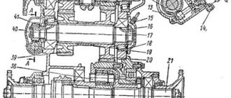
Double-disc clutch for Ural cars has the following models and configurations: YaMZ-236K, YaMZ-238, YaMZ-238N, YaMZ-236KM, YaMZ-238M, YaMZ-238NM. The Ural-4320, 5557 clutch is a double-disc, dry, friction type, with a peripheral arrangement of cylindrical springs. Driven clutch discs Ural-4320, 5557 with a diameter of 400 mm, with a spring-friction type torsional vibration damper, with asbestos-based friction linings. The clutch release clutch Ural-4320, 5557 with a special angular contact bearing moves towards the engine when disengaged. The clutches of Ural vehicles of the YaMZ-236 and YaMZ-238 configurations are identical in design and differ only in the number of pressure springs. The YaMZ-238 clutch can be made in a sealed version. Rice. 7. Clutch of the car Ural-4320, 5557 (YaMZ-238) 1 – rod; 2 – ring; 3 – disc spring; 4 – bar; 5 – pull lever; 6 – pull lever fork; 7 – adjusting nut; 8 – spacer plate: 9 – locking plate; 10 – spring loop of the pull-out lever; 11 – clutch release clutch with bearing; 12 – lubricant supply hose to the clutch release clutch; 13 – clutch release fork; 14 – thrust ring of pull-out levers; 15 – clutch release fork shaft; 16 – clutch casing; 17 – pressure spring; 18 – thermal insulating gasket; 19 – pressure plate; 20 – flywheel; 21 – driven disks; 22 – middle drive disk; 23 – release spring; D – minimum stroke of the release clutch Housing 16 (Fig. 7) of the Ural-4320, 5557 clutch, stamped from sheet steel, with the pressure disk 19 assembled is installed on the engine flywheel 20, and the driven disks 21 are on the splined part of the input shaft of the gearbox. The front and rear driven discs of the Ural-4320, 5557 clutch are not interchangeable and are installed in a certain position. The driven disks of the Ural-4320, 5557 clutches are clamped by a constant force of cylindrical pressure springs 17 between the engine flywheel, the middle and pressure disks. The YaMZ-236K clutch has eighteen pressure springs, the YaMZ-238 clutch has twenty springs. Thermal insulating gaskets 18 are placed under the springs on the pressure disk side. The pressure and middle drive disks of the Ural-4320, 5557 are connected to the flywheel with four spikes located on the outer surface of the disks. When clamped, the driven disks transmit engine torque to the transmission input shaft. The clutch is released by clutch 11. The clutch with the bearing, moving towards the engine, removes the pressure plate from the driven disk, transmitting force through four rigid release levers 5. The working stroke of the clutch release clutch Ural-4320, 5557, taking into account free play, should not be less than 18.2 mm (size “D”). The amount of free play is regulated by the clutch release mechanism. The thrust ring of the pull-out levers moves towards the gearbox by 27 mm due to the permissible wear of the friction linings. Guaranteed clearances between the driven disks and the friction surfaces of the flywheel, middle drive and pressure disks when the Ural-4320, 5557 clutch is disengaged as the linings wear out are ensured by a mechanism for automatically adjusting the withdrawal of the middle disk.
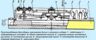
It consists of rods 1, fixed in each of the four studs of the middle drive disk, split rings 2, which require a certain force to move along the rod, thrust strips 4, which are bolted to the flywheel with the clutch casing, and disc springs 3 mounted on the rod between ring 2 and bar 4. When the clutch Ural-4320, 5557 is disengaged, the pressure plate 19 moves back at least 2 mm and releases the rear driven disk 21. The middle drive disk of the clutch 22, under the action of the spring 23, also moves back until it stops rings 2 into bar 4 through the disc spring, by an amount of 1.2±0.1 mm, freeing the front driven disk. As the friction linings of the Ural-4320, 5557 clutch wear out, the middle drive disk, under the action of the pressure springs of the pressure disk, moves to the flywheel, the rings 2 rest against the clutch housing, moving along the rods 1 and maintaining the size between the rings and the disc springs. When installing the Ural-4320, 5557 clutch with a mechanism for automatically adjusting the withdrawal of the middle disk to the flywheel, follow the following procedure: Install the front driven disk. Install the middle drive disk with rods. Install the rear clutch disc. Install the pressure plate and housing assembly, securing it to the flywheel with eight short bolts. Place split rings 2 onto rods 1 until they stop at the clutch housing. Place the four disc springs with the convex side facing the split rings. Install four thrust bars and secure them with the housing to the flywheel using eight long bolts. After installing the Ural-4320, 5557 clutch on the flywheel, make sure that the rings on the rods rest against the housing, providing a gap of 1.2 ± 0.1 mm between the rings and the disc springs when the clutch is engaged. When the linings of the driven discs wear out, the end of the clutch release clutch Ural-4320, 5557 will rest against the end of the bearing cover of the gearbox input shaft; in this case, replace the worn linings of the driven discs with new ones. Lack of free play of the clutch release clutch Ural-4320, 5557 will lead to failure of the pressure bearing and increased slipping of the driven discs. The free play of the clutch release clutch Ural-4320, 5557 (size “A”) can be adjusted by changing the length of the release mechanism rod or the length of the amplifier cylinder rod. Adjusting the clutch of Ural-4320, 5557 vehicles When assembling the clutch pressure plate (basket) Ural-4320, 5557 with the housing assembly, adjust the position of the thrust ring. This adjustment is made in a device having an installation dimension of 27 ± 0.1 mm (Fig. 6 pull-out levers with adjusting nuts, with the casing and pressure plate in a fixed position.
Rice. 8. Device for assembling the pressure plate (basket) Ural-4320, 5557 with casing assembly 1 – stand; 2 – guide pin; 3 – casing mounting bolt; 4 – thrust ring of pull-out levers; 5 – pull lever; 6 – adjusting nut; 7 – locking plate; 8 – support plate; 9 – pressure plate By adjusting, ensure dimension “B” is equal to 64±0.1 mm, while the thrust surfaces of all four release levers 5 must simultaneously touch the thrust ring 4. Distortion of the thrust ring will lead to uneven withdrawal of the pressure disk when the Ural-4320 clutch is disengaged , 5557 or its abnormal operation. After adjusting the position of the thrust ring using the adjusting nuts 6, install the locking 7 and support plates 8 of the adjusting nuts. Tighten all eight bolts securing the locking and support plates, installing spring washers under the bolt heads. In the case of using a pressure plate with a casing complete with driven disks after repair, on which friction linings with a thickness of 4.15 mm are installed, when adjusting the position of the thrust ring, set dimension “B” to 67 ± 0.1 mm. Clutch release drive Ural-4320, and its components Clutch release drive Ural-4320, 5557 is mechanical, with a pneumatic type amplifier.
Rice. 9. Clutch control drive for the Ural-4320, 5557 vehicle with a brake valve 1-pneumatic valve; 2-lock nut; 3-adjusting bolt; 4-rod with compensator; 5-bracket; 6.22-brake valve levers; 7-clutch drive lever; 8.19-hoses; 9-clutch pedal rod; 10-brake pedal rod; 11- clutch pedal shaft lever; 12-shaft clutch pedal; 13-clutch pedal travel limiter; 14-brake pedal release spring; 15-clutch pedal spring; 16-clutch pedal; 17-brake pedal; 18-clutch fork shaft lever; 20-pneumatic cylinder; 21-brake valve rod; Pneumatic cylinder 20 (Fig. 9) of the Ural-4320, 5557 clutch amplifier (PGU) is installed on the gearbox housing and acts on the clutch release fork shaft lever 18. The cylinder is controlled by a pneumatic valve 1, which is mounted on rod 4. Hose 8 connects the valve 1 with the vehicle's pneumatic system. When the clutch pedal 16 is acted upon, the force through the lever 11 and the rod parts 9 is transmitted to the rod of the pneumatic valve 1, opening its valve. Air pressure from the pneumatic system of the Ural-4320, 5557 vehicle through hose 19 enters cylinder 20, which additionally acts on lever 18. Adjusting the moment of turning on the pneumatic valve in the presence of air in the pneumatic system of the Ural-4320 vehicle: - disconnect hose 19 from valve 1; — unscrew the adjusting bolt 3, ensuring a gap between the bolt and the valve stem; — press the clutch pedal 16 until the force increases significantly; — tighten bolt 3 until the tap valve opens (air outlet from the control line of tap 1); - tighten the adjusting bolt 3 by 0.5-1.0 turns and lock it with nut 2. Adjusting the full and free travel of the clutch pedal Ural-4320, 5557 Full travel of the clutch pedal Ural-4320, 5557 - 195-220 mm, adjusted by the limiter adjusting bolt 13 strokes of the clutch pedal and is carried out only if there is air pressure in the car’s pneumatic system of at least 0.6 MPa (6 kgf/cm2). The free play of the Ural-4320 clutch pedal should be within 50-60 mm. The amount of free play of the clutch pedal Ural-4320, 5557 is determined in the absence of air pressure in the vehicle’s pneumatic system by pressing the hand on the pedal; The beginning of the clutch disengagement is felt by a significant increase in force. Adjusting the free travel of the Ural-4320 clutch pedal is carried out by changing the length of rod 9. To do this, you need to: - disconnect rod 9 from lever 11; — loosen the lock nut of the thrust fork and unscrew the fork to increase the free play or tighten it to decrease it; — connect the rod to the lever and tighten the fork locknut while maintaining the screw-in length not less than the thread diameter; — Check the free play of the pedal. If the thread of the rod is used completely, it is necessary to move the lever 18 counterclockwise to one spline, additionally adjusting the rod 4. Single-plate clutch of Ural-4320, 5557 cars Depending on the model of the power unit, Ural cars can be equipped with single-plate clutches YaMZ-181, YaMZ-182 and their modifications. Clutch Ural-4320, 5557 - friction, dry, diaphragm pull-out type. Driven clutch disc Ural-4320, 5557 with a diameter of 430 mm, with a spring-friction type torsional vibration damper, with friction linings on a non-asbestos base. The Ural-4320 shut-off clutch with a radial bearing moves away from the engine when turned off. Characteristics and parameters of the single-disc clutch Ural-4320, 5557 Clutch model - YaMZ-181, YaMZ-182 Clutch type - dry, friction, single-disc, with a diaphragm extension spring and asbestos-free linings. Engine torque, Nm (kg/cm) - minimum - 650 (66), 820 (84) - maximum - 820 (84), 1100 (112) Driven clutch disc - with damper, spring-friction type, with elastic fastening of one from friction linings. Dimensions of friction linings, mm - outer diameter - 430 - inner diameter - 240 - thickness - 4.3 Driven disk hub splines: - number of splines - 10 - inner diameter, mm - 34 - outer diameter, mm - 42 - cavity width, mm — 6 Fig. 10. Clutch of cars Ural-4320, 5557 models YaMZ-181, YaMZ-182 1 - driven disk; 2 — pressure disk; 3 — thrust ring; 4 — clutch release; 5 - lubrication hose; 6 — clutch release fork; 7 — tension spring; 8 — clutch release fork roller. The diaphragm clutch Ural-4320, 5557 models YaMZ-181 and YaMZ-182 (Fig. 10) consists of driving and driven parts, as well as parts of the clutch release mechanism installed on the gearbox. The leading part of the Ural-4320, 5557 clutch - pressure plate 2 with a casing is installed on the engine flywheel and secured with M10 bolts (12 pcs.) with a diameter of 450 mm. Centering is carried out along a cylindrical groove with a diameter of 475 mm on the flywheel and clutch housing. The clutch pressure plate Ural-4320, 5557 (YaMZ-181, YaMZ-182) is connected to the casing using 4 sets of plates that provide centering, axial movement and transmission of torque from the casing to the pressure plate. To prevent rotation of the diaphragm spring relative to the casing and pressure plate, the latter is equipped with 6 pairs of bushings with special brackets. The use of these brackets allows you to maintain constant contact of the pressure plate with the spring and ensure the release of the former when the clutch is disengaged. Driven part of the clutch Ural-4320, 5557 (YaMZ-181, YaMZ-182) - driven disc 1 is installed between the flywheel and the pressure plate and is centered along the splines of the gearbox input shaft. The Ural-4320 clutches use a driven disk with a spring-friction type damper with elastic fastening of one of the friction linings. Thanks to this, the Ural-4320, 5557 clutch reduces the dynamic loads on the transmission during sudden shifts (starting off, changing gears), and also eliminates resonance phenomena and reduces the maximum “peak” torque values during steady vehicle movement. The Ural-4320 clutch release mechanism consists of clutch 4 (Fig. 10) with a bearing, fork 6 and roller 8. The clutch is connected through a thrust ring 3 to a diaphragm spring using a locking device. The release spring 7 (Fig. 10) eliminates rotation and axial movements of the sleeve 7 (Fig. 11) relative to the thrust ring 1 (Fig. 11). As the friction linings wear out, the clutch release clutch 4 (Fig. 10) moves together with the spring towards the flywheel, while the design of the clutch release drive Ural-4320, 5557 (YaMZ-181, YaMZ-182) ensures rotation of the fork 6 (Fig. 10 ) clockwise after selecting the gap between the fork legs and the clutch due to periodic adjustment of the drive, or gradual rotation due to the design of the hydraulic drive. Locking device of the Ural-4320, 5557 clutch The locking device (Fig. 11) of the Ural-4320, 5557 clutch includes a thrust ring 1, a sleeve 7 of the coupling bearing with a shaped groove, a spring ring 2 of circular cross-section, as well as a locking ring 5. Fig. eleven. Clutch locking device Ural-4320, 5557 (YaMZ-181, YaMZ-182) 1 - thrust ring; 2 — spring ring; 3 — spring washer; 4 — retaining ring; 5 — lock ring; 6 — safety ring; 7 — bearing sleeve. Thrust ring 1 is installed on the diaphragm spring when assembling the pressure plate with the casing and is held by spring washer 3 and retaining ring 4. In the figure, the clutch is locked (connected) to the thrust ring. Inside the clutch bearing bushing 7, a safety ring 6 is installed, which has a protruding mustache on the outside that prevents accidental disconnection of the clutch release clutch and thrust ring 1. The release of the clutch Ural-4320, 5557 (YaMZ-181, YaMZ-182) is ensured by turning the shaft clockwise. The permissible direction of movement of the clutch and rotation of the shaft to disengage the clutch is shown in Fig. 10 arrows. Moving the coupling and turning the shaft in the opposite direction is not permissible. Removing and installing the clutch of the Ural-4320, 5557 (YaMZ-181, YaMZ-182) car Fig. 12. Basic provisions of the locking device 1 - thrust ring; 2 — spring washer; 3 — retaining ring; 4 — spring ring; 5 — lock ring; 6 — bearing sleeve; 7 — safety ring. Removing the Ural-4320, 5557 clutch from an engine with an installed gearbox is carried out in the following order: Unscrew the nut securing the lubrication hose. Push the lubrication hose into the clutch housing cavity. Remove the gearbox, while the clutch release clutch YaMZ-181, YaMZ-182 remains on the thrust ring of the diaphragm spring. Align the semicircular groove on the clutch release clutch in its front part with the protruding mustache of the safety ring 6 (Fig. 12) and, drowning it with some object, hold it in the recessed position through the central hole of the clutch release clutch. Rotate the lock ring relative to the bushing so that the protrusions of the ring coincide with the grooves of the bushing (position “d”). Push the clutch towards the flywheel until it stops, and the spring ring 4 will come out of the shaped groove of the thrust ring and fit into a rectangular position (position “d”). Disconnect the clutch by moving it in the opposite direction (away from the flywheel), while the spring ring remains in the rectangular groove of the thrust ring (position “e”), and is then removed from it. Remove the clutch pressure plate (basket) Ural-4320, 5557 (YaMZ-181, YaMZ-182) with the casing, to do this, unscrew the clutch mounting bolts, gradually in several steps, avoiding significant distortions of the pressure spring. Installation of the Ural-4320, 5557 clutch on the engine is carried out in the following order: Using a special mandrel, install the driven disk on the flywheel, while the friction lining riveted to the spring plate should be located towards the pressure plate, and the elongated part of the hub should be outward (away from the engine ). Install the clutch pressure plate (basket) Ural-4320, 5557 with the housing assembly, ensuring alignment of the mounting holes of the clutch housing and the flywheel. Hand tighten the clutch mounting bolts to a depth of at least 4 mm. Tighten the clutch mounting bolts with Mkr 60...70 Nm in several stages, evenly pulling the pressure plate with the casing towards the flywheel, avoiding significant distortions of the pressure (diaphragm) spring. Using a special mandrel, center ring 3 (Fig. 10) relative to the axis of the engine crankshaft. The design of the locking device for the clutch release mechanism Ural-4320, 5557 (YaMZ-181, YaMZ-182) requires special rules for installing the gearbox on the engine. Installing the gearbox and inserting the Ural-4320 clutch into engagement with the thrust ring of the diaphragm spring is carried out in the following order (the lever is located on the left of the engine): Turn the locking ring 5 on the clutch so that its protrusions do not coincide with the grooves of the clutch bearing sleeve ( position "a"). Make sure that the clutch release clutch is retracted all the way to the bearing cover of the gearbox input shaft by spring 7 (Fig. 10). Install the gearbox and secure with two bolts. Move the clutch release clutch Ural-4320, 5557 (YaMZ-181, YaMZ-182) to the thrust ring until it stops, to do this, use the technological lever to turn the clutch release fork shaft counterclockwise. In this case, the spring ring falls into the shaped groove of the thrust ring (position “b”, Fig. 12). By turning the clutch release fork shaft clockwise, move the clutch away from the engine (position “B”). Make sure that the clutch release clutch Ural-4320, 5557 is engaged with the thrust ring by applying additional force to the clutch in the direction from the engine. Finally secure the gearbox. Checking the quality of installation of the Ural-4320, 5557 clutch (lack of “driving”, control of the amount of torque on the fork shaft) is carried out with the engine not running. To do this, you need to turn the fork shaft at an angle of 9º30'...11º clockwise, which corresponds to moving the clutch 11...13 mm from the engine. In this case, the output shaft of the gearbox, when the gear is engaged, must rotate when applying a torque of no more than 5 Nm (0.5 kg/cm).
_________________________________________________________________________________________
- GAZ-3307 clutch maintenance
- Steering system GAZ-3307
- Gearbox parts for GAZ-3307
- Maintenance of the rear axle GAZ-3307
- Maintenance of the fuel system of the D-245 diesel engine
- Clutch GAZ-3309 with a diesel engine
- Operations for disassembling the GAZ-3309 gearbox
- GAZ-3309 front axle service
- Repair of cardan shafts of GAZ-3309 cars
_________________________________________________________________________________________
_________________________________________________________________________________________
- Operations for assembling basic components of the ZIL-130 engine
- Service and repair operations for the ZIL-130 gearbox
- Maintenance and repair of ZIL-130 clutch
- Repair and adjustment of the rear axle ZIL-130
_________________________________________________________________________________________
- KAMAZ-4310, 43118, 43114
- KAMAZ-5320, 55111, 53212, 5511, 55102
- KAMAZ-65115, 6520, 65117
- KAMAZ-4308
- Engine KAMAZ-740
_________________________________________________________________________________________
- Parts of the cylinder block and head of the YaMZ-236 engine
- Service maintenance of the YaMZ-236 piston group and crankshaft
- Diagnostics and technical adjustments of the YaMZ-236 engine
- Design and adjustment of fuel injection pump and injectors of the YaMZ-236 engine
- Cylinder block and piston YaMZ-238
- Components of the YaMZ-238 diesel fuel supply system
- Design and adjustment of the fuel injection pump of the YaMZ-238 diesel engine
- Technical design of the YaMZ-239 gearbox
_________________________________________________________________________________________
- Components of the front axle and steering rods of the Maz-5516, 5440
- Steering system of Maz-5516, 5440 cars
- Clutch and gearbox parts Maz-5516, 5440
- Maintenance of drive axles of MAZ-5516, 5440 vehicles
- Power steering for Maz-5551, 5335 cars
- Maintenance of cardan transmission of Maz-5551, 5335 cars
- Maintenance and adjustment of clutch MAZ-5551, 5335
- Repair and service of the rear axle of MAZ-5551, 5335 cars
_________________________________________________________________________________________
- Gearbox Ural-4320
- Construction and adjustment of Ural-4320 bridges
- Maintenance of transfer case Ural-4320
- Steering components Ural-4320
_________________________________________________________________________________________
- Servicing the KRAZ-255, 260 gearbox
- Steering mechanism and power steering Kraz-255, 260
- Adjustments and repairs of the power steering cylinder and steering rods of the Kraz car
- Drive axle components and drive shafts Kraz-255, 260
Ural motorcycle clutch device
Chapter IV. TRANSMISSION OF MOTORCYCLES “URAL”, “DNEPR”
The transmission is designed to transmit torque from the engine crankshaft to the wheel(s) of the motorcycle, change it and stop the transmission of rotational force.
The transmission consists of a clutch, gearbox, driveshaft and final drive.
CLUTCH OF MOTORCYCLES “URAL”, “DNEPR”
The clutch is designed to transmit torque from the engine to the gearbox, disconnect the engine from the gearbox during gear changes, and smoothly engage when the motorcycle is moving away. The double-disc dry clutch consists of driven and driven parts and a clutch release mechanism.
Rice. 4.1. Clutch discs of the motorcycle “Dnerpr-11/16. 1 — disk assembly; 2 - hub; 3, 5, 6, 7 - disks; 4 - spring; 8 - screw; 9 - rivet
Rice. 4.2. Clutch release mechanism: 1 — cotter pin; 2 — washer: 3 — ring; 4 - slider; 5 - bearing, 6 - tip; d 1 - rod, 8 - oil seal; 9 — rod assembly, 10 — lever; 11 - bolt; 12 - nut; 13-axis
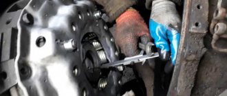
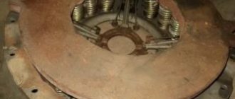
The need to check clutch parts arises if the clutch pins and pin holes in the drive discs wear out, the pin fits in the flywheel become loose, the splines in the hub of the driven discs wear out, the fastening of the disc hubs becomes loose, the friction discs wear out and the elasticity of the springs decreases. If the fingers are worn out by more than 1 mm, they need to be replaced. To do this, press out the worn pins, having previously measured the amount of protrusion of the ends relative to the plane of the flywheel. Press in new fingers (Fig. 4.3), leaving an allowance at the ends for grinding. Then the fingers are polished. After grinding, the ends of the fingers should be in the same plane. The runout of the ends relative to the conical seating surface of the flywheel should be no more than 0.2 mm. If the walls of the holes in the drive disks are damaged, then you need to drill new holes with a diameter of 196 mm between the old ones (hole diameter 12.5 - 12.57 mm). Discs with worn out linings and splines in the hub are replaced with new ones. If rivet connections become loose, they must be riveted or replaced. Clutch springs must have the same stiffness. New parts, when compressed to 21 mm and depending on the load, are marked with paint: 17.5 - 19.0 kgf - gray, 16.0 - 17.5 kgf - black. The free springs are about 45 mm long.
Clutch Ural 375.4320.5557.43206
On KamAZ-4310 and Ural-4320 vehicles, a friction dry double-disc clutch with a peripheral arrangement of springs is installed. The clutches of both cars are the same, their parts are interchangeable, the difference is in the drive. On the KamAZ-4310 vehicle the clutch drive is hydraulic with a pneumatic booster, on the URAL-4320 vehicle the clutch drive is mechanical. The clutch is called frictional and dry because the transmission of torque in it is carried out due to the friction forces between the disks, the surface of which must be dry; the disks are compressed by springs located along the periphery of the disks; The torque is sensed by two driven discs. The clutch parts are located in an aluminum housing bolted to the flywheel housing. On top of the crankcase there is a hatch for inspection of clutch parts; the hatch is closed with a lid. The bottom of the crankcase has two hatches, also closed with lids. A crowbar is inserted through the front (small) hatch to rotate the flywheel. The rear hatch cover has a threaded hole for grease drainage; Before crossing the ford, this hole is closed with a plug screwed into the blind boss of the lid. The clutch consists of driving and driven parts, a pressure device and a release mechanism with a drive. The driving parts include the flywheel, casing, pressure and middle 2 disks. The stamped casing is installed on the flywheel using mounting bushings and secured to it with twelve bolts. The pressure and middle disks each have four protrusions on their outer surfaces that fit into the grooves of the flywheel. Torque is transmitted through the protrusions from the flywheel to the discs; This installation of the disks allows them to move axially when the clutch is disengaged. The protrusions of the middle disk contain a lever mechanism that automatically adjusts the position of the disk when the clutch is disengaged. This mechanism consists of a lever with an axis and a spring. The lever axis is screwed into the hole in the protrusion and secured against turning with a rivet. The lever is placed loosely on the axle and is pressed by a spring, one end of which rests against the plane of the groove, the other against the hole in the lever. The spring constantly strives to rotate the lever around the axis, while one end of the lever rests against a block pressed into the flywheel, and the other against a specially hardened place on the pressure disk. When the clutch is released, the lever mechanism sets the disc to the middle position and ensures clean release.
On page: 1000255075100
Sorting: DefaultName (A -> Z)Name (Z -> A)Price (ascending)Price (descending)Rating (descending)Rating (ascending)Model (A -> Z)Model (Z -> A )
Shaft 200-1601215 of the clutch release fork, wheeled vehicle URAL 375, LAZ 699R. This is a long, metal, milled shaft on which is put on the clutch fork 200-160120 of the vehicle engine. Located inside the clutch housing of the car. Made of high-strength steel capable of endure heavy mechanical loads during vehicle operation.
Clutch release fork 200-160120, wheeled vehicle URAL 375, LAZ 699R. This is a metal, milled, curved fork that is put on the clutch platen of the vehicle engine. Located inside the clutch housing of the car. Made of high-strength steel capable of withstanding large mechanical loads in the process operation of the vehicle.Used for...
Clutch disc 375-1601091 drive, middle, plate, main clutch couplings of the wheeled vehicle Ural 375, Ural 4320, Ural 43203-10, Ural 5557, Ural 5323. This is a cast, milled, round metal disk. Installed inside the clutch basket of the car. Made from high-strength steel capable of withstanding large mechanical loads during vehicle operation. Applied to all series..
Clutch disc 375-1601130 driven assembly (feredo disc), main clutch couplings of a wheeled vehicle Ural 375, Ural 4320, Ural 43203-10, Ural 5557, Ural 5323. It is a rigid, rough plate riveted to a rigid hub, fibrous material is visible on the disc linings or fine-grained structure. The composition includes a heat-resistant filler and a thermosetting organic binder, additional...
Clutch pressure plate 375-1601090 basket, main clutch couplings of a wheeled vehicle Ural 375, Ural 4320, Ural 43203-10, Ural 5557, Ural 5323. The clutch basket consists of a pressure plate, power springs, tabs, casing, clutch disc. Pressure plate provides connection between the driven disk and the flywheel. When the clutch is disengaged, the pressure plate presses on the driven disk, which in turn engages...
Clutch housing 375-1601015-D main clutch housing, wheeled vehicle URAL 375, LAZ 699R. This is a round, milled housing with mounting holes along the edge. Installed on the outside of the vehicle’s engine unit. Covers the main elements of the vehicle’s clutch. Made of high-strength steel capable of withstanding large mechanical loads during the operation of the pipeline..
Clutch release clutch 200-1601180-A release bearing assembly, wheeled vehicle URAL 375, LAZ 699R. The release bearing is one of the most important parts in the clutch device. The bearing is located between the clutch basket and its drive mechanism. Its task is to put pressure on the petals of the basket, as a result of which the discs separate and the clutch disengages. The bearing rotates due to...
Lever 200-1601217 of the clutch release fork shaft, wheeled vehicle URAL 375, LAZ 699R. This is a long, curved, metal lever that fits onto the clutch shaft 200-1601215 of the vehicle engine. Located outside the clutch housing of the vehicle. Made of high-strength steel capable of carrying large mechanical loads during vehicle operation.
agro-detal.com
Clutch m72
The M72 clutch has three steel drive disks 4, 8 and 11, connected to the engine flywheel using pins, and two driven disks 7 and 9, mounted on the splines of the gearbox input shaft using hubs 6.
Compression of the discs (clutch engagement) is carried out using six pressure springs 3, the total force of which is about 100 kg.
When the clutch is engaged, the engine crankshaft is connected to the transmission input shaft, and they rotate as one unit.
The clutch is turned on and off using the clutch lever mounted on the left handlebar. This lever is connected by a cable to lever 19 on the clutch axis, which, through a slider and a thrust ball bearing, can press on rod 13.
Replacing the clutch on a Ural-4320 car
Answers to popular questions. Most often, Ural 4320 drivers encounter the following problems:
- Slipping. This may be due to abrasion of the friction disc linings, in case of oiling of the rubbing surfaces, breakdown of the shutdown drive or pressure spring.
- "Leading". This occurs due to malfunctions of the shutdown drive, deformation of the pressure disk, exceeding the maximum curvature and runout of the driven disk, as well as destruction of its linings.
- Clutch noises. They may appear due to the lack of lubrication in the clutch bearing or in case of its destruction or wear.
To correct these breakdowns, you need to replace worn clutch elements with new ones. Sometimes the clutch is installed/dismantled. Before carrying out repair work, it is necessary to thoroughly clean the workplace, prepare the tool, if the cause of the malfunction is known, buy the necessary Ural 4320 parts for the clutch, preferably original ones.
Removing the clutch
The clutch is removed from the engine along with the gearbox. This is done in the following order:
- The nut securing the lubricant hose is unscrewed.
- A lubricant hose is pushed into the cavity of the clutch housing.
- The gearbox is removed. The clutch release clutch should remain on the thrust ring of the diaphragm spring.
- The semicircular groove of the release clutch is aligned with the protruding lug of the safety ring. It needs to be sunk with something and held there through the central hole of the coupling.
- The lock ring is rotated relative to the bushing so that the grooves of the bushing and the protrusions of the ring coincide.
- The clutch is pushed towards the flywheel until it stops. The spring ring should come out of the groove of the shaped thrust ring and take its place in the rectangular one. This will be position "d".
- The coupling is disconnected. To do this, it must be moved in the opposite direction from the flywheel. The spring ring remains in the rectangular groove (position “e”) and is then removed from it.
- The pressure disk with the casing is removed. To do this, the clutch mounting bolts are gradually unscrewed in several steps. Severe distortions of the spring are not allowed. Defects of parts are carried out with the clutch disassembled. Find out what parts will be needed.
Installation on the clutch motor
- Using a special mandrel, the driven disk is installed on the flywheel. The friction lining on the spring plate is located towards the pressure disk, the elongated hub part is located outward from the motor.
- The pressure disk with the casing is mounted as an assembly, ensuring the coaxial position of the flywheel holes and the fastening of the clutch casing.
- We tighten the clutch bolts by hand to a depth of at least four millimeters.
- The bolt tightening torque limits are 60-70 Nm. It is necessary to tighten it gradually, evenly, without allowing the spring to distort.
- The ring must be centered relative to the axis of the crankshaft using a special mandrel.
Features of gearbox installation
- Turn the ring on the coupling so that the protrusions do not coincide with the grooves of the bearing sleeve (position “a”).
- Unscrew the coupling until it stops.
- Install the gearbox and secure it with bolts.
- Move the clutch release clutch towards the thrust ring until it stops.
- Turning the clutch release fork shaft clockwise, move the clutch away from the engine (position “b”).
- Make sure that the coupling engages with the thrust ring. To do this, you need to apply additional force in the direction from the motor.
- The gearbox is finally secured.
Return to list of articles>>>
uralval.ru
M72 gearbox
The M-72 is equipped with a four-speed two-way gearbox, consisting of a gear shift mechanism and a starting mechanism (starter).
The power transmission of the box consists of eight gears and two shift clutches mounted on the primary 1 and secondary 4 shafts of the gearbox.
The primary shaft rotates on ball and cylindrical roller bearings.
The secondary shaft rotates on two ball bearings.
The two gears of the input shaft are made in one piece with it.
The secondary shaft gears 2, 9 and 16 rotate freely on bronze bushings 3, 10 and 15, which are pressed onto the secondary shaft.
All gears (their modulus is 2.5 mm) of the primary and secondary shafts are in constant mesh.
Gears 2 have spiral teeth and the rest have straight teeth.
Clutches 6 and 13 are designed for gear shifting.
Clutch 6 is used to engage third and fourth gears and is mounted on a splined sleeve 12 connected to the shaft with keys. Has end cams for engagement.
Clutch 13 is used to engage first and second gears and is mounted directly on the shaft splines. It has through holes that serve to engage with gears.
If the clutches are set to neutral, the transmission output shaft will not rotate.
A disk 17 is mounted on the shank of the secondary shaft and secured with a nut, through which torque is transmitted to the drive wheel.
FAQ on replacing the clutch on a Ural 4320 car
The most common malfunctions of the clutch of the Ural 4320 vehicle are:
1. Slipping due to wear of the friction linings of the disc, oil getting on the rubbing surfaces, malfunction of the shutdown drive, breakage of the pressure spring.
2. “Driving” due to incorrect operation of the shutdown drive, warping of the pressure plate, unacceptable curvature and runout of the driven disk, destruction of the driven disk linings.
3. Noises at the clutch installation site may occur due to lack of lubrication in the release clutch bearing or its wear.
To eliminate these faults, it is necessary to replace worn clutch parts with new Ural auto parts. In some cases, it is necessary to remove/install the clutch, which will be discussed in more detail below. Before starting repairs, it is necessary to ensure the cleanliness of the workplace, the availability of the necessary tools, and, if the cause of the malfunction is known, buy Ural 4320 spare parts (preferably original ones) for the clutch.
Removing the clutch from the engine.
The clutch is removed from the engine with the gearbox installed. The order of work is as follows.
1. Unscrew the nut securing the lubrication hose.
2. Push the lubricant hose into the cavity of the clutch housing.
3. Remove the gearbox. The clutch release clutch must remain on the diaphragm spring thrust ring.
4. We combine the semicircular groove of the release clutch in its front part with the protruding mustache of the safety ring 6 (Fig. 1) and, having sunk it with something, hold it in this position through the central hole of the clutch release clutch.
5. With respect to bushing 6, rotate the locking ring 5 (Fig. 2) so that the protrusions of the ring and the grooves of the bushing coincide.
6. Push the clutch all the way towards the flywheel. Spring ring
4 should come out of the shaped groove of the thrust ring and fit into a rectangular one. This corresponds to position "d".
7. Disconnect the release clutch. To do this, move it in the opposite direction from the flywheel. In this case, the spring ring should remain in the rectangular groove of the thrust ring (position “e”), and then be removed from it.
8. Remove the pressure plate with the casing. To do this, gradually unscrew the clutch mounting bolts in several steps, while not allowing significant distortions of the pressure spring. With the clutch disassembled, we carry out troubleshooting of the parts and determine the required Ural auto parts.
Rice. 1 Locking device 1 – thrust ring; 2 – spring ring; 3 – spring washer; 4 – retaining ring; 5 – locking ring; 6 – safety ring; 7 – bearing sleeve
Figure 2 – Basic provisions of the locking device 1 – support ring; 2 — spring washer; 3 — retaining ring; 4 – retaining ring; 5 — lock ring; 6 — bearing sleeve; 7 — safety ring.
Installing the clutch on the engine.
The procedure for installing a repaired or new clutch on an engine is as follows:
1. Using a special mandrel, install the driven disk on the flywheel. In this case, the friction lining attached to the spring plate should be located towards the pressure plate, and the elongated part of the hub should be located outward from the engine.
2. Install the pressure plate with housing assembly, ensuring the coaxial location of the mounting holes for the clutch housing and the flywheel.
3. Manually tighten the clutch mounting bolts to a depth of at least 4 mm.
4. The tightening torque of the clutch mounting bolts should be within 60...70 Nm. We carry out the tightening in several stages, evenly pulling the pressure disk with the casing towards the flywheel and avoiding distortions of the diaphragm (pressure) spring.
5. Using a special mandrel, it is necessary to center ring 3 (Fig. 3) relative to the axis of the engine crankshaft.
Figure 3 – YaMZ 182 clutch 1 – driven disc; 2 — pressure disk; 3 — thrust ring; 4 — clutch release; 5 - lubrication hose; 6 — clutch release fork; 7 — tension spring; 8 — clutch release fork roller.
The installation of the gearbox has some features related to the design of the clutch release mechanism locking device.
The procedure for installing the gearbox and engaging the release clutch with the thrust ring of the pressure spring is as follows:
1. Turn the lock ring 5 (Fig. 2) on the coupling so that its protrusions do not coincide with the grooves of the coupling bearing sleeve, which corresponds to position “a”.
2. The clutch release clutch by spring 7 (Fig. 3) must be retracted all the way to the bearing cover of the gearbox input shaft.
3. Install the gearbox and secure it with 2 bolts. It is important to remember that when installing the transmission, do not move the clutch release towards the flywheel after it is connected to the diaphragm spring.
4. Move the clutch release clutch all the way to the thrust ring. To do this, use the technological lever to turn the clutch release fork shaft. In this case, the spring ring should fit into the shaped groove of the thrust ring (position “b”).
5. By turning the clutch release fork shaft clockwise, move the clutch away from the engine (position “B”)
6. By applying additional force to the clutch release clutch in the direction from the engine, we make sure that it is engaged with the thrust ring.
7. We finally secure the gearbox.
After installing the clutch with the gearbox with the engine not running, it is necessary to check the quality of the installation by checking for lack of guidance and the amount of torque on the fork shaft:
1. Turn the fork shaft clockwise at an angle of 9.5°...11°, which corresponds to moving the clutch from the engine by 11...13 mm.
2. When the gear is engaged, the gearbox output shaft should rotate when applying a maximum torque of 5 Nm.
3. Clockwise rotation of the clutch release shaft is shown in Figure 3.
mega-avtogal.ru
Switching mechanism m72
The shift mechanism is used to control the shift clutches.
The couplings are moved using two forks 7 and 14, which fit into the annular grooves of the couplings. The forks are mounted on the guide roller 8 and have pins that fit into the grooves of the switching sector. The sector can be installed in five different positions and secured with a ball lock. The sector can be moved by a foot pedal or a handle.
The foot pedal has an eye with a pin that fits into a groove in the lever. Associated with the roller switching sector.
The presence of a selector greatly simplifies and speeds up the process of changing gears when riding a motorcycle.
Trigger
The M72 starting mechanism is designed to start the engine.
A special shaft is mounted in the gearbox housing, on which gear 2 rotates on a bronze bushing. The latter, through the intermediate gear, is in constant engagement with the input shaft gear.
Integrated with gear 2 is a ratchet, inside of which there is a pawl 4, mounted on an axis 5 with a spring and a pin 3. The latter constantly strives to turn the pawl towards the teeth of the ratchet.
When you press the trigger lever, the pawl rests on the teeth of the ratchet and causes rotation of the gearbox input shaft, and therefore the engine crankshaft.
The trigger lever returns to its original position under the action of a return spring, and to soften the return blow there is a buffer 7, consisting of a thrust pin and a spring.
Design and operation of the clutch and clutch drive of the Ural-4320 vehicle
Construction machines and equipment, reference book
Category:
Kamaz Ural cars
Design and operation of the clutch and clutch drive of the Ural-4320 vehicle
The clutch of the Ural-4320 vehicle is similar in general design and operation to the clutch of the KamAZ-5320 vehicle, but has some design features.
The clutch housing is connected to the flywheel housing by its front mating surface, and the gearbox housing is attached to its rear part. The engine, clutch and gearbox are assembled at the factory, forming the power unit.
To ensure that the vehicle can overcome fords up to 1.5 m deep, the cavity of the clutch housing is sealed. In its lower part there is a lid in which a drainage hole is provided, which is blocked by a plug when overcoming a ford.
The clutch drive is mechanical. The pedal is connected through a system of rods and levers to the clutch fork shaft lever. The drive includes a servo spring, which makes it easier to hold the clutch in the disengaged position.
Rice. 4.6. Clutch control drive of the Ural-4320 vehicle: 1 - clutch pedal; 2 - intermediate shaft; 3.9 — clutch control drive levers; 4 - traction; 5 — servo spring; 6 — pedal shaft; 7 — clutch pedal shaft lever; 8 — pedal travel limiter; 10 — clutch release rod; 11 — clutch fork shaft lever
When you press the pedal, the rod moves upward, the lever with intermediate shaft 2 rotates clockwise, the lower end of the lever moves forward along with the clutch release rod, and the clutch release fork shaft lever connected to it rotates counterclockwise, the fork shaft and the fork press on the clutch release with the bearing, thereby ensuring the clutch disengages.
Read more: Adjusting the clutch and its drive
Category: — Kamaz Ural cars
Home → Directory → Articles → Forum
stroy-technics.ru
Lubrication of M72 box parts
The gearbox parts are lubricated with oil poured through a hole located on the left side of the gearbox housing.
To lubricate the bronze bushings of the secondary shaft gears, there is an oil pocket in the secondary shaft bearing cover, and a blind hole is drilled along the axis of the secondary shaft. The oil that accumulates in the pocket enters the shaft hole and flows through radial drillings under the influence of centrifugal forces. To the inner surfaces of bronze bushings.
Oil leakage from the gearbox is prevented by washers and seals. All these parts must be inspected in a timely manner and replaced if there is significant wear.
Main gear m72
The transmission of torque from the gearbox to the drive wheel is carried out using cardan and final drives.
The cardan shaft 5 is driven into rotation from the secondary shaft of the gearbox through an elastic coupling 2, consisting of two steel disks and a rubber coupling 4 with a bandage. One of these discs is fixed to the secondary shaft of the gearbox, and the other 3 is pressed onto the end of the propeller shaft. Each disc has two fingers that fit into the holes of the rubber coupling.
At the other end of the cardan shaft there is a fork consisting of a cross 12, mounted in the sockets of the cardan forks 9 and 10, which have needle bearings 8.
The driveshaft is made of a special alloy and can twist under increasing loads. When unloaded from effort, it returns to its original state.
The main gear consists of 7 driving and 11 driven gears placed in the gearbox housing 6.
Gears rotate in bearings and transmit torque to the drive wheel. Through the internal gearing formed by the driven gear of the rear wheel and the hub connected to the driven gear of the main transmission.
Transmission oil in the amount of 150 grams is poured into the main gear housing.
URAL 4320 30 (31) — Drive of clutch and brake pedals for MO
| 1 | 4320-1602119 Spring | 1 | 42,00 |
| 2 | 4320-1602055 Clutch pedal shaft | 1 | 150,00 |
| 3 | 4320-1602063 Pedal bracket | 1 | 1055,00 |
| 4 | 5557Я-1602060 Clutch pedal shaft lever | 1 | 555,00 |
| 5 | 250512-P29 Nut M10-6H | 2 | call to order |
| 6 | 252136-P2 Washer 10.OT | 2 | call to order |
| 7 | 5557Я-3504026 Brake pedal shaft lever | 1 | call to order |
| 8 | 258038-P29 Cotter pin 3.2x16 | 3 | 2,00 |
| 9 | 339640-P52 Finger 10x28 | 2 | 21,00 |
| 10 | 5557-3504010 Brake pedal assembly | 1 | call to order |
| 11 | 201500-P29 Bolt M10-6gх32 | 2 | call to order |
| 12 | 339200-P29 Union | 1 | 20,00 |
| 13 | 5557-1602194-10 A tube | 1 | 145,00 |
| 14 | 4320-3504032 Spring | 1 | 90,00 |
| 15 | 339434-P29 Clamp | 1 | call to order |
| 16 | 252037-P29 Washer 6 | 1 | 3,00 |
| 17 | 250508-P29 Nut M6-6N | 1 | call to order |
| 18 | 200263-P29 Bolt M8-6gх35 | 1 | call to order |
| 19 | 252135-P2 Washer 8T | 1 | call to order |
| 20 | 375-3506023 Clamp gasket | 1 | call to order |
| 20 | 316169-P2 Cork | 1 | call to order |
| 21 | 339098-P29 Clamp | 1 | call to order |
| 22 | 5557Я-1602082 bracket | 1 | 945,00 |
| 23 | 5557Я-1602120 Drive shaft lever | 2 | 425,00 |
| 24 | 5323-1602178 Spacer | 1 | 60,00 |
| 25 | 260062-P52 Finger 10x40 | 1 | 22,00 |
| 26 | 4320-3504065 Traction | 1 | 270,00 |
| 27 | 250515-P29 Nut M12x1.25-6N | 1 | call to order |
| 28 | 258052-P29 Cotter pin 4x20 | 2 | call to order |
| 29 | 260087-P52 Finger 12x35 | 1 | call to order |
| 30 | 375-3504036 Fork | 1 | 190,00 |
| 31 | 5557Я-1609005 Pneumatic cylinder assembly | 1 | 90,00 |
| 32 | 5557Я-1602074-01 Clutch fork shaft lever | 1 | 710,00 |
| 34 | 264020-P29 Oiler 1.3 | 1 | call to order |
| 35 | 5557Я2-1602032 Clutch release shaft | 1 | 195,00 |
| 36 | 5557-3504015 Pillow | 1 | 35,00 |
| 37 | 5557Я-3504058 Brake valve control lever | 1 | 710,00 |
| 38 | 5557Я-1602010 Clutch pedal | 1 | 590,00 |
| 39 | 4320-3504052 Pedal link assembly | 1 | 320,00 |
| 40 | 5557Я-1602057 Clutch release rod | 1 | 355,00 |
| 41 | 250510-P29 Nut M8-6N | 1 | call to order |
| 42 | 4320-1602091 Tip | 1 | call to order |
| 43 | 4320-1602070-01 Pedal buffer | 1 | call to order |
| 44 | 252016-P29 Washer 14 | 1 | call to order |
| 45 | 338062 Key 22x9.5 segment | 1 | call to order |
tprostor.ru