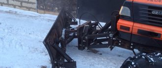
Automatic coupler SA-1 80-2709010, N110.000 for MTZ, YuMZ tractors
Designation: SA-1 80-2709010, Н110.000
Width (m) / Height (m) / Length (m): 0.75 x 0.2 x 1 Weight, kg: 14.28
Automatic hitch SA-1
designed for attaching to and disconnecting from the hitch mechanism from the driver's seat mounted machines and implements that have a “reciprocal” unit - an automatic coupler lock. The automatic hitch provides free hanging of machines shifted to the side relative to the tractor axis by up to 120 mm, with the lock tilted forward up to 15°, and also tilted to the side up to 15°.
Dimensions of automatic coupler SA-1
The SA-1 automatic coupler is a frame of a flat welded structure, consisting of two square pipes located at an angle of 65°. At the bottom of the automatic coupler frame, pins are welded on the outer and inner sides, with which the automatic coupler is installed in the holes of the hinges of the longitudinal rods of the hitch mechanism. When installing the automatic coupler on the hitch mechanism, its longitudinal rods must be attached to the outer pins of the frame. In cases where the rods interfere with work (for example, when cultivating tall crops at 700 mm row spacing), it is recommended to attach longitudinal rods to the inner fingers.
At the top of the frame, strips with holes are welded for attaching the automatic coupler to the rear hinge of the central link of the hitch mechanism. The rod pin can be inserted into a hole in the bar or into a groove. It is recommended to connect the central rod to the groove. In this case, the frame will be in an inclined position from the tractor, which makes it easier to hang the machine. If there is insufficient transport clearance or uneven movement of the working parts of the machines, it is necessary to connect the central link to the frame through a hole in the bar. When connecting the central link to the frame through a hole and tilting the machine lock back, before hanging the machine, you should lengthen the central link, and after hanging, shorten it to the required length.
The pawl serves to secure the connection between the frame and the lock of agricultural machines. The lock is a flat structure consisting of two channels, welded at an angle of 65° and fastened with a tie. During operation, the toe of the pawl should rest on the lock stop. To ensure a tight connection, it is necessary to use eccentrics located on the rear plane of the machine lock to establish a minimum gap between the stop and the toe of the pawl.
Automatic coupler SA-1: 1
– dog;
2
– spring;
3
– handle;
4
– bar;
5
– frame;
6
– finger;
7
– channel;
8
– communication;
9
– eccentric;
10
– emphasis;
11
– groove for the automatic coupling pawl.
Automatic coupler operation
The connection of the SA-1 automatic coupler frame to the lock occurs as follows. When the frame is inserted into the cavity of the lock, the pawl, under the action of a spring, slides into the groove of the lock and secures the connection. To disconnect the frame from the lock, you need to use a cable pulled into the tractor cabin to turn the handle and disengage the pawl from the lock stop. Then, holding the handle, lower the hitch mechanism with the frame installed on it (until the frame comes out of the lock) and move the tractor away from the mounted machine. When storing the automatic coupler frame in the lock of an agricultural machine, insert the cotter pin into the hole in the pawl. This will prevent the frame from falling out of the lock if you accidentally press the handle.
For several decades, the SA-1 automatic coupler has been successfully used in conjunction with MTZ tractors, which saves a lot of time and helps to use the equipment as efficiently as possible. Read everything about the MTZ automatic coupler, its purpose, design and operating features in the proposed article.
Description and characteristics
The MTZ 82 linkage cylinder is the most important component of the design of the working mechanism; it is used to hold it in a certain position, raise, lower, and perform various tasks. A similar element is used for the correct operation of attachments, as well as trailed devices. This kind of element has the identification number ts-100x200-3, which makes it easy to find it in the spare parts catalog. Among the characteristics of such a product it is worth noting:
- weight - 22 kg;
- nominal/maximum pressure - 16/20 MPa;
- working cylinder diameter - 10 cm;
- piston stroke - 20 cm;
- rod - 4 cm;
- nominal/maximum operating speed - 0.15-1 m/s.
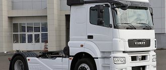
It should be mentioned that a cylindrical element of this type has a wide range of applications; it is used in popular models of tractors MTZ 50, 80, 82, as well as YuMZ-6, which makes the components interchangeable. The hydraulic cylinder model is of the piston type and has a two-way operating principle. Moreover, it is made according to an outdated model, which is currently practically not used in new technology. It is called the main one because it is used to perform most tasks.
In addition to the above-mentioned cylinder, the design of the product contains 2 more similar elements with a diameter of 7.5 cm. This kind of product is called remote, since they are mounted on the body of the unit, and communication with the main hydraulic system is carried out through special pipelines and hoses.
Device
It should be noted that all cylinders installed in the tractor design are completely identical to each other in their operating principle and technical design, and their main difference is the size of the parts. When studying the structure of the main hydraulic cylinder, it is advisable to highlight several key elements of its design. Among them:
- frame;
- back and front covers;
- rod cavity and fork;
- oil line;
- piston and rod;
- MTZ 82 hydraulic cylinder mounting bracket, studs and valves.
The internal structure of the product deserves a more detailed consideration. The body appears to be a special pipe, the inside of which has been processed. It is sealed by means of rings, which are located in the corresponding cavities of the back and front covers. The studs provided by the design are used to securely connect such elements to the body, and a fork is located at the end of the back cover. It is important to remember that the cylinders with a diameter of 7.5 cm use cast iron as the material for the cover, while the main hydraulic cylinder uses high-strength steel. The oil required for the operation of the mechanism enters through the corresponding hole located in the front cover. The cylinder of the MTZ tractor is constructed in such a way that when the rod is retracted, the attachment is lifted. The stop in the extreme position does not interfere with the movement of the rod, but helps move the valve to a special place on the product cover.
Operation of automatic coupler type SA-1
To operate the automatic coupler, it is necessary to equip the tractor with a frame, and all attachments with locks. This task is made easier by the fact that today frames and locks can be purchased separately, or the corresponding number of locks can be made.
The frame is fastened to the hinge at three points: with the fingers to the longitudinal rods of the hinge, and with the help of the jaws in the upper part to the hinge of the central link of the hinge. Since there are grooves and holes in the cheeks, the frame can be mounted to the central rod in various positions (vertically or at an angle), which are adjusted by the position of the fingers in the grooves. For example, for some types of attachments it will be more convenient to install the frame strictly vertically, and for some - with a slight tilt back. The locking part of the hitch is also secured to the attachment at three points using various bolts or pins.
Operating the automatic coupler is not particularly difficult and is accessible to machine operators even with little experience. Hanging of machines and units is carried out in the following order:
- Position the attachment so that the tilt angles of the lock and the frame coincide (displacement from the tractor axis by 120 mm, as well as tilt forward and sideways (right or left) up to 15 degrees is allowed);
- Drive the tractor in reverse to the attachment, lower the attachment;
- Place the frame under the lock;
- Raise the hinge so that the frame fits into the lock;
- Raise the hitch until the pawl enters the lock hole and is secured by the spring;
- If necessary, provide additional fixation of the lock using a cotter pin in the pawl or a pin in the roller.
Now the equipment is ready for operation, and the rigidity of the connection of the automatic coupler parts is sufficient to carry out most work without the risk of losing the equipment.
Disconnecting attachments is easier:
- Pull the cable to retract the lock pawl and release the frame;
- Slowly lower the hinge, the frame should come out of the lock on its own;
- Move the tractor away from the released attachment.
Sometimes it happens that the automatic coupler does not disengage; in this case, you can try to pull the cable harder, as the lock pawl may jam. If jamming of the frame and lock bodies occurs, then it makes sense to lower the hitch with increased force. However, this method should be used with caution, since in this case deformation and breakage of the hinge parts is possible.
Over time, the SA-1 automatic coupler is subject to deformation and corrosion, and its lock wears out, so you should periodically check the entire structure and eliminate any problems that have arisen. If cracks appear, it makes sense to completely replace the automatic coupler, since welding will only help for a short time. Malfunctions of the lock (pawl and its drive) should be eliminated as quickly as possible, since this mechanism plays a key role in the reliable fixation of attachments and the safety of work.
With proper operation and timely repair, the SA-1 automatic coupler will become a reliable and simple assistant in performing hundreds of operations in any field.
Installing attachments on a tractor is not always easy and requires some time. However, today the AC-1 automatic coupler from MTZ is widely used, which easily and at minimal cost solves the problem of installing mounted units. Read about the MTZ automatic coupler, its design and operation in this article.
not always simple and requires some time. However, today the AC-1 automatic coupler from MTZ is widely used, which easily and at minimal cost solves the problem of installing mounted units. Read about the MTZ automatic coupler, its design and operation in this article. Purpose of the SA-1 automatic hitch Only in rare cases is a tractor needed by itself - the main value of this machine lies in the ability to install various attachments and implements on it. It is thanks to the attachments that the tractor becomes a rural worker, a housing and communal services worker or an assistant in any other field. To install attachments on the tractor, a special device is used - the rear linkage. In our country, the most widespread is the MTZ three-point hitch, which over the past decades has been used both on wheeled Minsk tractors and on tractors from other factories. The rear linkage is universal, it allows you to install the most
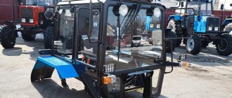
MTZ tractors with Lombardini engines and attachments
For several years now, the Minsk Tractor Plant has been offering new models of tractors with Lombardini power units. Our company, being a dealer of MTZ, supplies these tractors, as well as all attachments for them and spare parts. Read about the new MTZ tractors with Lombardini and attachments for them, the features and advantages of this equipment in this article.
A roll bar is installed. Equipped with a Lombardini LDW 1603/B3 engine with 36 hp. "Belarus-422". A universal compact tractor with a traction class of 0.6, but due to the more powerful Lombardini LDW 2204 diesel engine (46.9 hp) it is capable of developing a traction force on the hook of up to 7.1 kN. The tractor has a 4x4 wheel arrangement (and the front axle is engaged automatically), is equipped with developed hydraulic and pneumatic systems, and can be equipped with a front PTO and a front hydraulic linkage system. Unlike the “younger” models, it is equipped only with a rigid cabin. Available in several modifications - basic 422, 422.1 and others. "Belarus-622". The most powerful and largest among Minsk mini-tractors with Lombardini engines, it is equipped with an LDW 2204T engine with a power of 60.2 hp. In general, the design and characteristics of the tractor correspond to the characteristics of the 422 model, but “Belarus-622” due to its increased traction
Agricultural tractors in Russia
Since tractors have been and remain the main equipment used in field farming, many Russian manufacturers have been trying to introduce original technical solutions in recent years.
The goal of our agricultural machine builders is not so ambitious - at least to retain in their hands part of the domestic market, which is rapidly being conquered by imported products. Annom with Valtra transmission with electro-hydraulic and mechanical switching. Mastering new classes Tractor manufacturing enterprises of the former USSR have always had one problem: mastering models of traction classes that are not in the nomenclature. And before anyone else, this problem was solved not by Russian designers, but by Belarusian ones, at the Minsk Tractor Plant, which was initially designed to produce tractors of only the 1.4 traction class. Initially, Minsk residents mastered the mass production of the highly sought-after “third grader” MTZ-2022, to which the Kirov Plant team responded by entering the market with a direct competitor, the K-300ATM. The specialists from Volgograd also did not remain in debt, having joined the “third-grader pioneers” using their VK-170. However, later, neighboring tractor manufacturers designed the MTZ-2822 class 5, which, in fact, is an upgrade of the famous Kirovets. True, the creators of the new model really creatively approached the development of a tractor with a classic design, equipped
User manual
The operation of the units does not cause any difficulties, which is due to the ease of use of the tractor’s hydraulic mechanism. In some cases, the unit may need to be adjusted correctly to make it effective and safe to use.
Adjustment is carried out by changing the length of the braces, as well as the thrust. With the help of the former, it is possible to adjust the transverse arrangement of the equipment, and with the help of the central rod, the longitudinal arrangement. Since the weight of most types of attachments used with tractors in this series is impressive, the mechanism periodically sags. This situation can be corrected using a special fixation mechanism, which is mounted directly on the cylinder bracket and allows you to securely secure its position.
Design and principle of operation of the automatic coupler
The automatic coupling SA-1 is a composite one; it contains two related components:
- Frame - mounted at three points on the rear linkage of the tractor;
- Lock - mounted in one way or another on attachments.
Frame.
It is an A-shaped structure of two square pipes connected by welding at an angle of 65 degrees. In the upper corner of the frame there are two transverse strips with holes and grooves into which the hinge pin of the central adjustable link of the hinge is inserted. The simplest locking mechanism is located here - a “pawl”, which is held in working position using a lever and a spring. The pawl lever ends with a handle, the end of which is connected to a cable - this cable is pulled into the cabin, and with its help the pawl is pulled back if necessary to disconnect the attachments. On top of the frame there is a centering roller (bushing), which can also be used for additional fixation of attachments. At the bottom of the frame there are pins with which it is attached to the hinges of the longitudinal rods of the hitch.
Lock.
It has an even simpler device - it is welded from two channels at the same angle of 65 degrees, in its upper part a steel triangular connection is welded, which provides rigidity to the structure and is a fixation element. An oval hole is cut out in the connection; an eccentric plate is mounted in its lower part with bolts.
The MTZ automatic coupler works as follows. If it is necessary to hang equipment, the frame is inserted into the lock by lifting the hinge; when it reaches the top point, the pawl enters the hole in the connection on the lock and snaps into place. The pawl has a hook-shaped shape, so it is locked with an eccentric on the lock, and the frame cannot disengage from the lock. If it is necessary to disconnect the equipment, the operator in the cab pulls the cable, the handle on the lock turns the lever, and the pawl disengages from the eccentric. In this position, the frame can freely come out of the lock, so when the hitch is lowered, the attachment is disconnected.
Possible faults
The MTZ hydraulic system is characterized by a long service life, simple and reliable design. However, with use, many of its parts may wear out, which leads to failure of the unit. If desired, repair work can be performed independently by performing troubleshooting, purchasing and replacing damaged elements. An example is hinge joints, which are subject to intense mechanical stress, which negatively affects their service life. In addition, it is often necessary to repair or replace the splined joints of the lift arms, as well as the shaft. Such problems lead to a significant increase in gaps, which complicates the adjustment of attachments and leads to a decrease in processing accuracy. In some cases, it may be necessary to weld and rework damaged areas of the structure.
Maintenance of the hydraulic system of the MTZ hinged mechanism comes down to timely lubrication of the mechanism using standard elements, as well as monitoring the degree of wear of the component elements.
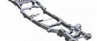
Rear linkage MTZ 82(80): device, adjustment and repair
The hitch is a universal equipment for connecting a tractor with mounted, semi-mounted and trailed type machines in working and transport positions. The device is a mechanical part of the tractor’s hydraulic linkage system, consisting of a system of articulated parts combined into a structure that ensures reliable connection and the specified position of the working parts of the devices and machines used. MTZ tractors are standardly equipped with a rear linkage; additionally, the machines can be equipped with a front linkage to place attachments at the front. The technical characteristics of the MTZ 80(82) linkage correspond to a load capacity of at least 3.2 tons.
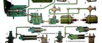
Rear linkage device
The structure is attached to the rear wall of the tractor rear axle housing. The upper rotary shaft of the hitch is placed with its axis in the cylindrical supports of the bracket, which is bolted to the upper edge of the rear wall of the axle housing. The central part of the shaft interacts through a splined connection through a lever 7 with a power hydraulic cylinder 6 , which provides lifting and lowering. On the left and right sides of the shaft there are lifting levers 5 connected to the corresponding left and right, vertically placed, length-adjustable braces 3 and 9 . The braces are connected to the lower longitudinal strips 4 and 10 .
The connection is made pivotally with fingers through forks 2 . With their front ends, the longitudinal left and right lower bars are attached to the edges of the axle installed in the lower part of the rear axle housing. The rear ends are equipped with spherical hinges 1 for convenient connection with the towbars of attached machines. Additionally, the lower bars are equipped with length-adjustable ties 12 . To ensure the connection of attachments and machines, the design includes a central upper rod 8 with connecting ball joints at the ends. Its front part is connected to the positioner bracket, the rear part is attached to the mounted device. In the standard configuration, a transverse bar 13 with a towing eyelet with a locking pin is hingedly attached to the rear ends of the lower bars for attaching towbars of machines and vehicles.
Considering the location of the attachment points of the lower longitudinal bars to the axle body, the MTZ rear linkage has a three-point design, which provides a fairly rigid attachment to the tractor without lateral movement of the attachment. This connection requires the obligatory deepening of the working tillage implements of the mounted machine when the unit turns.
Automatic hitch SA 1 (Triangle)
A device for automatically attaching machines on MTZ 80(82) “Automatic coupler SA 1” (the so-called “triangle”), is attached by three points to the hitch - two hinges of the ends of the lower longitudinal bars and the central link. The contact connecting part of CA 1 is made of a metal profile in the shape of a triangle. Fixation is carried out with a spring lock with a latch. When hanging, the triangle fits its profile into the internal profile of the triangle of the machine being hung. With the upper guide angle 8, the device, when connected, aligns the hole of the outer triangle with the spring-loaded latch 4 of the triangle on the tractor. If a match is made, the latch closes automatically under the action of a spring. To disconnect the mounted device, press down the lock lever 9 and disengage the triangle 3 by lowering the linkage. The drive of the control lever for the coupling device lock is brought out using a cable 10 to the driver's seat to ensure operation without outside help.
Automatic coupler SA 1 on the MTZ 80 hitch
The CA 1 device is universal and is used in mounted systems of tractors of different brands.
The MTZ 82(80) hitch has a similar design to all wheeled tractors of the MTZ family and universal row-crop machines of the YuMZ-6, T-40, T-25 brands. Additionally, the hitch of modern tractors can be equipped with a lift-type towing device, as well as towing devices of various designs. Crawler tractors are equipped with a reinforced hitch with the possibility of two or three point connection of the hitch to the tractor.
Adjustments
The position of the mounted machine is adjusted by changing the length of the braces 3.9 and the upper central link 8 . The braces adjust the transverse arrangement of the attachments. Standardly, the left brace is not adjusted; adjustment is made by changing the length of the right brace, equipped with a handle 15 for convenient rotation of the screw. The position of the machine in the longitudinal position relative to the horizon is adjusted by changing the length of the upper central link.
The tension of the couplers connected to the longitudinal lower links and the tractor body adjusts the lateral movement of the attachment relative to the axis of movement of the tractor. Loose ties allow for slight movement. To ensure a rigid position of the machine, for example, for inter-row cultivation of crops or during sowing with a mounted seeder, the couplers are tensioned as much as possible, eliminating lateral rocking.
For convenient adjustment of length and tension, threaded pairs of screws and ties have left and right threads. The tie rods are secured with control nuts.
An increase in load capacity is achieved by installing additional pins at the connection of the brace forks and longitudinal bars in additional holes located closer to the rear mounting hinges. In this case, the forks must be turned with the grooves forward so that the forks do not affect the pins connecting the ends of the lower longitudinal rods. To ensure reliable fastening of connections in the hinge joints, it is necessary to use standard locking pins and cotter pin nuts for the tension bolts of the structure.
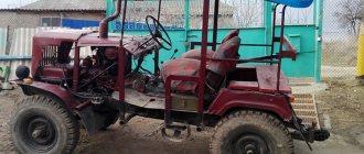
Automatic coupler SA-1
Maybe someone has a drawing with the dimensions of the SA-1 automatic coupler, please share.
Maybe someone has a drawing with the dimensions of the SA-1 automatic coupler, please share.
You will need to take measurements.
Maybe someone has a drawing with the dimensions of the SA-1 automatic coupler, please share.
You will need to take measurements.
The first is from that topic, the second is from the Internet
The first is from that topic, the second is from the Internet
If there is at least one part, dad or mom, so to speak, it’s not at all difficult to do, just adjust it to the existing part
a channel for a frame with a width of 80 mm on the outside. The length is made according to a square - on it and the entire frame is welded, the top trim, the bar for the retainer.
a channel for a frame with a width of 80 mm on the outside. The length is made according to a square - on it and the entire frame is welded, the top trim, the bar for the retainer.
The first is from that topic, the second is from the Internet
This is from the topic “Lift for a tractor. Load capacity 600-700 kg” mihail150 writes: It’s very easy to make a frame for a corner. I do this for myself. I take two channels, put them on the corner and cut off the corners. I am preparing two kasynki and one plate. I apply the finished channels to the corner and press them so that they do not move from their place. At the top I weld the channels on both sides with gussets, and on the back side I weld a plate for the locking hook to the channels. The frame is ready.
Trouble-shooting
The main problems are the wear of the hinge joints of the braces and bars, as well as the splined joints of the rotary shaft and lifting levers. Increased gaps do not allow the structure to be fixed in the desired position and complicate the adjustment process when adjusting the depth of processing and the accuracy of the movement of working tools mounted on agricultural implements. cars Elimination of increased play in joints is achieved by replacing worn parts. In some cases, welding and subsequent machining of worn surfaces to the required dimensions are used.
Maintenance of the structure consists of lubricating the rotary shaft through standard oilers, monitoring the integrity of parts, as well as regularly checking the reliability of hinged and threaded connections.
Reasons for lowering the hitch
The cause is a malfunction in the tractor's hydraulic system. In addition to the usual oil leakage from the system, one of the main reasons is wear of the piston and rod seals of the hitch's power cylinder. The development in the seals of the unit allows oil to flow from the lifting cavity to the lowering cavity and the cylinder rod changes its position, lowering the linkage. The second reason for lowering is a malfunction of the hydraulic distributor as a result of debris or general contamination. If flushing does not eliminate the cause, the unit is sent for repair.