To find out how to check the energy accumulator on a KAMAZ, how to replace the KAMAZ energy accumulator, you should first remember that KAMAZ vehicles use several types of energy accumulators. Any energy accumulator includes three parts:
- The lower part is attached to the bracket related to the brake caliper using M16 studs.
- The middle part is made of an aluminum-based alloy and is connected to the part located below by means of a clamp with 2 bolts.
- The upper part, which is a glass made of steel, is attached to the part located in the middle with 8 M8 bolts.
DO IT YOURSELF
How to remove and disassemble the side rear view mirror
Doing it yourself will be much faster and more profitable, because only you need it, and not a repairman. First of all, we find the cause of the breakdown of the energy accumulator and go to the store, buy the necessary spare parts and begin independent repairs.
Remove the top part of the energy accumulator. We leave the compressed air supply hose to remove the retaining ring inside the pusher. It is located on a bolt and holds the thrust bearing. Unscrew the thrust bearing and you will see it. To get to it, you need to supply compressed air to the energy accumulator, and then the pusher will go inside the chamber and we can get the locking ring. Another moment you need to make a hook from the electrode to hook it, look at the photo, as I did.
Next, after removing the stopper, we bleed the air from the energy accumulator, remove it and disassemble it. We will disassemble it using 4 bolts with nuts, the length of which is about 12 cm. We unscrew 4 bolts from the cover of the energy accumulator, and leave 4. We will insert our long 4 bolts into these holes and tighten them with a nut. Next, we remove the other 4 small bolts and we will only have our 4 long bolts left.
Slowly turning each nut, we will disassemble the energy accumulator no worse than a press, only ourselves. After disassembly, I wash all the parts and especially look at the cylinder where the piston and cuffs go, so that there are no scuffs or deep scratches there.
Installation
How to check the fuel pressure regulator and common causes of malfunction
On a truck, the brake chamber and the spring energy accumulator connected to it are mounted on the brackets of the expansion knuckles. Fastening is carried out with two nuts screwed onto the chamber bolts. The installation area must provide sufficient space to connect hoses and piping for compressed air supply. In general, installing an energy storage device is a relatively simple process.
First, you need to dismantle the brake chambers and connect them to energy accumulators. Hoses for air in the cavity above the diaphragm are connected to the corresponding fittings. Next, install and power the receiver. It supplies air to the accelerator valve and the parking brake lever. Next, the tube goes to the accelerator valve in the upper part.
Then you just need to supply air to the top of the energy accumulator - where the springs are installed. If you need to replace the energy battery, you can use this brief instruction.
Causes of malfunction of the KAMAZ energy accumulator
The following types of mechanical damage to this device occur:
- body dents;
- pipeline blockage;
- pusher jamming.
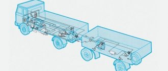
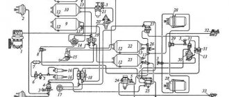
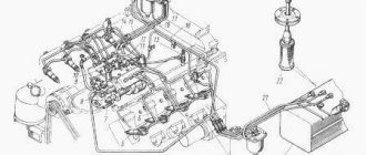
The KamAZ vehicle has a dual-circuit pneumatic braking system, which ensures vehicle safety in all driving modes. During braking (when you press the brake pedal), compressed air is immediately supplied to the brakes of all wheels. The parking brake only locks the wheels of the middle and rear axle. The main element of the drive of such a brake is the energy accumulator. KamAZ has 4 such devices - 1 for each wheel of the rear bogie.
Energy accumulator repair
How to remove the drum from the washing machine and disassemble it
Repair of energy accumulators can be carried out by car service specialists, or, if you have a spare original repair kit, independently.
Causes of battery failure
The list of possible malfunctions is presented as follows:
- mechanical damage or “aging” of the housing, since during operation cavities form on the working surface of the cylinder, which leads to a violation of the chamber’s tightness, making it difficult to repair;
- aging or ruptures of the disk membrane, which indicates the need to sort out the assembly;
- failure of the cover connecting elements.
How to disassemble an energy accumulator
It is better to organize repair of the unit in a service center, but if a malfunction occurs on the road, it is carried out in the field, and the need for disassembly and the sequence of actions remains unchanged. After the unit is removed from the trouser installation site, the order of work is as follows:
- Remove the top part. The air supply hose is moved to the side - this makes it more convenient to remove the rear retaining ring of the pusher after dismantling the thrust bearing. It should not be muted.
- The tap opens the air supply. The pusher plunges, opening access to the retaining ring. The stopper is removed with a homemade hook (it’s convenient for hooking). The groove is cleaned of dirt.
- Close the air supply. Remove the required assembly.
- Of the eight short standard bolts, the covers are unscrewed and four are removed. In their places, long bolts with a locknut and a nut are placed (their size is from 120 mm). Unscrew the remaining four small bolts.
- Gradually releasing the long bolts smoothly releases the working spring. This operating procedure eliminates the need to use special bench devices.
- Replace or restore broken parts. You need to assemble your unit in reverse order.
How to release the brakes on an energy accumulator
The emergency wheel locking mode is activated due to a malfunction in the pneumatic system. But repairing or towing the car is possible after manually releasing the energy accumulators that do not work. The following order is provided:
- use a socket wrench to remove the screw;
- excess pressure equalizes atmospheric pressure;
- the thrust bearing transmits force to the piston sufficient to compress the spring and move the diaphragm;
- The rod with the support disk, moving, unlocks the wheels.
Replacing the energy accumulator
It is necessary to take care in advance about purchasing a new device, for example, the Turbostar brand. Due to the fact that the units are normally located on bridges, they are replaced at a repair pit. The order is as follows:
- The brake system is relieved of operating pressure.
- The work area on the vehicle is cleaned of dirt and moisture.
- Remove the brake chambers. Unscrew the fastening screws of the old unit, disconnect the air supply hose - the energy accumulator is dismantled.
- It is necessary to carefully place the new unit in its original place and tighten the bolts firmly.
- Included in the high pressure system. The resever is refilled, and the pressure in the pipeline increases.
- They check the quality of the connections and how the system will work by increasing the pressure to operating pressure, followed by repeated release.
How to replace the brake energy accumulator on a MAZ 5432 is presented in the following video:
Adjusting the energy accumulator
If the idle clearance of the chamber rod is exceeded by more than 40 mm, after the bulkhead, a tight fit of the brake pads is not ensured, therefore, it is impossible to reliably hold the car in the parking lot on slopes of the road. In this case, adjustment of the rod stroke is necessary. The condition for its implementation is a disabled brake system and “cold” pads and drums. The sequence of actions is presented as follows:
- loosen the tension of the plug-clamp by a couple of turns;
- turning the axis of the worm mechanism, set the gap - 20 mm;
- fix the position with a stopper;
- the operation is performed with all nodes, the difference in stroke between them should not exceed 3 mm.
Why does the part break?
The energy accumulator is considered an important element of the pneumatic brake drive. Most often it breaks due to depressurization of the system. Experts recommend checking the operation of the air hoses first to understand whether there is an air leak or not.
The health of the energy accumulator is affected by:
- truck load;
- terrain;
- method of operation;
- quality of installed spare parts.
Most often, the connection point between the pipeline system and the hose breaks. They are the first thing they look at when making a diagnosis. If the connection is broken, the problem can be fixed using normal tightening movements. If it turns out that this is where air is leaking, then you will have to buy a new device and install it. Often the brakes stop functioning properly due to damage to the accumulator housing. Usually the cause is corrosion or a dent. Manufacturers argue for this by saying that they use metal that is not very wear-resistant, since it must be bent. As a result, over time, KamAZ drivers are faced with the fact that the cylinder gradually begins to leak air. The entire system is completely depressurized. To repair the part, you need to buy a new cylinder glass for subsequent installation. The most common reason for the failure of an energy accumulator is a burst pressure spring or a worn membrane that allows air to pass through and does not create the required pressure.
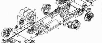
Energy accumulator MAZ device and functions
Trailer brake control valve
Most trucks, including MAZ and KAMAZ, are equipped with a braking system powered by a pneumatic drive. The operation of the units is ensured by creating force in the brake chamber. As a result, the pads in the drum are released. But this option is only suitable for service brakes that are used when driving with the engine running. For the operation of the reserve and parking braking systems, a MAZ spring energy accumulator is required.
The principle of operation of the MAZ energy accumulator
A modern device stores the energy that is required to operate car brakes in the absence of a source of compressed air, that is, when the engine and compressor stop.
The durable KAMAZ MAZ energy accumulator has a small compressed spring in which energy is stored.
If necessary, it expands as much as possible, forcing the brake mechanisms in the wheels to work. First, the spring is compressed due to the force of air supplied by the pneumatic system.
When using a handbrake, a spring creates a slight force to hold the shoes on the drum.
If malfunctions occur, the MAZ energy accumulator is capable of providing emergency braking.
MAZ energy accumulator - design and functions
The spring-pneumatic unit consists of:
- Cylindrical body made of durable metal;
- Powerful coil spring;
- Piston in the form of a cylinder with a pusher;
- Release screw and small nut.
There are fittings in special chambers of the MAZ energy accumulator. The device is installed on the brake chamber so that the piston pusher is opposite the hole in the chamber. To effectively release air when the spring is compressed, a drain tube is provided.
The type of mechanism is indicated by a fractional number, where the first digit indicates the effective area of the membrane in the brake chamber. For example, a MAZ 24 energy accumulator.
The most common system malfunctions are damage to the housing, wear of the diaphragm, and breakage of the lid bots. It is necessary to regularly inspect the mechanisms for breakdowns and, if necessary, repair or replace parts.
Varieties by connection method
In this case, energy accumulators are divided into two categories:
- Flange with two clamps.
- Flange with clamp and bolted connection.
When installing an energy accumulator, a flange is always used to connect the mechanism to the brake circuit. It serves not only to secure components. Their correct location also depends on it. Thus, when replacing an energy accumulator, the flange plays the role of centering and maintaining distance. If you use an element of the second type, here the flange is connected to the EA using several bolts and nuts. In the first case, the connection is simpler and is carried out using a metal clamp.
What other differences are there between energy accumulators? They differ in the effective area of the membrane or piston. This characteristic is expressed in square inches.
The most common energy accumulators today are those with a membrane or piston area of 20, 24 and 30 square inches. For a brake chamber, the area of the corresponding components varies from 12 to 30 square inches. If the energy accumulator is sold assembled, then this value is indicated by two digits separated by a fraction. The first number always indicates the area of the chamber membrane. And the second one speaks about the area of the energy storage membrane.
Brake systems. Pneumatic drive. Spring energy accumulator. Repair.
How to disassemble a headlight?
Repair of spring energy accumulator. To remove the spring energy accumulator (see Fig. 92), disconnect the hoses and unscrew the nuts securing it to the bracket. Disassembling the energy accumulator after removing the hose and disconnecting from the pneumatic chamber must be done in the following sequence: · unscrew the pusher 11 (Fig. 123.a) and remove the sealing ring 12 from it; · having unscrewed screw 19 from cylinder 15 a few turns (approximately 5mm), unscrew the nuts 9 bolts securing flange 10 to cylinder 15 and separate them
Remove O-rings 6, 7 and 8 from the flange; · screw screw 19 until it stops and install the cylinder in the device (Fig. 123.b) so that the stop 21 of the device covers the head of the screw, and, carefully rotating the handle 22 of the device, compress the spring 5, while the amount of recess of the piston 14 into the cylinder 15 is not must exceed 60mm; · Having sunk the package of parts 2, 16 and 18 (Fig. 123.c) beyond the rubber ring 1, remove the retaining ring 17 from the screw 19 with a special tool; · release piston 14 until spring 5 is completely relaxed, carefully rotating the handle of the device in the opposite direction; · having removed the cylinder, piston and spring from the device, remove the remaining parts 2, 16 and 18 (Fig. 123.d), remove guide ring 3 and seal 4 from the piston, remove spring 5, remove rubber ring 1 from the screw, unscrew screw 19 from the cylinder and remove the sealing washer 20
Before assembly, all rubbing parts must be lubricated with a thin layer of CIATIM-221 lubricant. Assembly should be done in the following sequence: · put sealing washer 20 (Fig. 124.a) on screw 19, screw it into cylinder 15 until it stops and put on rubber ring 1; · install spring 5 into the cylinder with a small turn outward; · put seal 4 and guide ring 3 on piston 14 and install the piston on the spring so that the end of the spring rests against the boss 13
Place flange 10 on the piston pipe, having previously inserted the sealing and guide rings 6 and 7 into it and put the sealing ring 8 on it; · install the assembled unit in the fixture (Fig. 124.b) so that the stop 21 covers the head of the screw 19 and, carefully rotating the handle 22 of the fixture, compress the spring 5 until the flange 10 comes into contact with the cylinder 15. At the same time, ensure that the guide ring 3 fits correctly ( Fig.124.c) into the cylinder
Connect the flange to the cylinder using bolts; · remove the assembled energy accumulator from the device and install on screw 19 (Fig. 124.a) sequentially thrust washer 2, needle bearing 18, stop 16, recess them beyond the rubber ring 1 and install retaining ring 17 so that it fits securely into the groove screw If compressed air is available, it can be supplied to the spring energy accumulator. In this case, the shank of the screw 19 will be closer to the edge of the piston tube, which will facilitate the installation of the thrust bearing 18; · carefully unscrewing the screw and compressing the spring, make sure that the piston is securely held by the retaining ring through the thrust bearing. Repeat this operation several times; · put o-ring 12 on pusher 11 and screw the pusher into the piston tube; · Having assembled the pneumatic chamber, connect its body to the flange using a clamp.
How to replace it yourself
To reinstall the “energy”, you must follow the instructions for installing the unit step by step.
A couple of tips for assembling the device:
- the operation must be carried out without dust, metal shavings and other impurities;
- using a special lubricant for rubbing parts will prolong service life;
- During assembly, rubber gaskets and seals should be handled carefully so as not to damage them;
- It is very important to follow the installation instructions.
In some cases, it may be necessary to turn off the “energy engine”. For this:
- prepare the tool, choose comfortable clothes, since the work is carried out without removing the device, directly under the machine;
- carefully unscrew the air supply hoses and clamp them;
- insert the release bolt into the grooves, screw the nut on top until it stops.
How to disassemble a KamAZ energy accumulator without a stand
The most convenient way to disassemble a KamAZ spring energy accumulator is to use a special stand. It is usually used at service stations and repair shops, but what to do if a breakdown occurs far from them? You can do this without a stand.
First you need to remove the air hoses and disconnect the energy accumulator from the pneumatic chamber. Further, the entire process must be carried out in strict sequence. Find videos and photos showing in detail how to disassemble can be found in the public domain on the Internet.
It is necessary to unscrew the pusher, remove the O-ring, then, slightly loosening the cylinder screw, disconnect the flange. Reinstall the cylinder and remove the retaining ring. Completely relax the spring, freeing the piston, remove it and the spring and cylinder. Remove the guide ring from the piston, unscrew the screw from the cylinder, and remove the sealing washer.
Assembly is carried out in the reverse order; parts that experience friction must be lubricated.
How to disinhibit
In order to release the truck from the parking brake, the control handle must be removed from the latch and moved to the lower position. The control compressed air is supplied via a pneumatic line through an open tap to the accelerator valve, which initiates the supply of the working medium from the receiver through the bypass valve into the lower cavity of the energy accumulator cylinder. The piston moves up and compresses the spring. The brake system rods move to their original position and release the pads. The truck is ready to move.
If there is no air in the system or the engine (compressor) breaks down and the vehicle needs to be towed, you must manually release the energy accumulator. To do this, use a socket wrench to remove the screws on the cylinders of all batteries. Thanks to the presence of a thrust bearing, the force will be transferred to the piston, which, while moving, will compress the power spring. Freed from the load, the return spring will move the diaphragm and the rod with the support disk to the upper position. The brake pad drives will return to their original state and unlock the wheels.
Situations often arise during flights when it is necessary to repair a KamAZ energy accumulator with your own hands in the field. The design of the device allows this to be done. However, it will be much easier to replace a defective energy accumulator with a working one and do the repairs in the garage.
Device
The part is practical and durable, but long-term or excessive use often requires repair of the KamAZ energy accumulator. Installing new components or restoring will extend the service life.
The device consists of the following elements:
- spring;
- cylinder;
- bypass tube;
- thrust bearing;
- piston: pusher.
The device also includes seals, screws and additional roller bearings. These elements make up the classic energy battery that KamAZ is equipped with. Transport cannot function normally if one of the system elements fails. Often it is enough to tighten the bolts, but sometimes it is necessary to replace hoses, screws, and bearings. The main thing is that the selected parts are original and completely match the brand.
The principle of operation of the energy accumulator
The task of the unit is to operate the brakes when the engine and compressor are not running. The operating principle is presented as follows:
- When the internal combustion engine starts, the compressor pumps air into the reservoir cylinder, then into the brake system.
- Through the pipes, the air is directed to the on-board energy accumulators, and the excess is bypassed.
- When the handbrake is removed, air enters the cylinders of the units, creating pressure sufficient to decompress the spring. The piston moves, mechanical drives unlock the brake pads - the car is ready to start moving.
- The parking brake is applied by releasing compressed air from the cylinders of the pneumatic accumulators, where, under the action of a spring, the drive blocks the hub pads.
Important! The occurrence of pneumatic malfunctions, in the form of depressurization or the entry of foreign media into the pipelines (condensation in winter), will lead to emergency blocking of the wheels of a truck or trailer.
Energy storage device
The design of the device includes:
- a housing in the form of a metal-containing cylinder with a lid and fitting;
- membrane;
- piston with pusher and support disk;
- twisted metal spring;
- thrust bearing, mounting bracket;
- release screw with roller bearing;
- bypass tube;
- seals and anthers.
Important! In the documentation for vacuum units from foreign manufacturers, the names of the same parts differ. But the functions and purpose do not change.
Energy storage units for trucks and trailers
Manufacturers of components and parts for pneumatic brake systems produce models that are divided according to the following characteristics:
- Layout method. On some vehicles and trailers, models are used complete with a brake chamber; on others, the unit is mounted on a separately designed chamber.
- Connection type. Fastening can be carried out using a single clamp with a tightening bolt. But reliability increases if a multi-clamp fastening is provided on the lower flange.
- Operating compressed air pressure. The requirements for the material of the cylinder, connection, and ability to pass air depend on it.
Important! Before replacing a failed unit, they clarify the type of fastening of the analogue - a substitute in a regular place, without the need to redo it, the diagram and technical characteristics of the device.
Design features of the mechanism
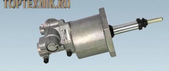
Regardless of the type, energy accumulators have the same design. So, the design is based on a metal body. It is presented in the form of an open glass. The latter can be with conical, cylindrical or spherical walls. There is a fitting at the bottom of it. It serves to connect the brake chamber and the under-piston space through a drain tube.
There is a coiled spring inside the glass. It is closed by a piston or an elastic membrane at the top. There is a tubular pusher in the center. If a piston is provided in the design of the car's energy accumulator, then the tubular pusher acts as a rod. In the case of a diaphragm, the pusher holds the rod rod. The latter is needed to drive the membrane and the brake chamber rod. A bolt is screwed into the lower part of it. It is necessary to release the brakes of the car in the event of a lack of air supply to the energy accumulator.
At the moment, modern energy accumulators differ in the way they are connected to the brake chamber and in the complete set. Regarding the last characteristic, EA can be represented by:
- Complete with brake chamber.
- As separate mechanisms for connecting to different types of cameras.
In the latter case, the unit is used to modernize or repair the brake chamber. If “F” has the first complete set, it can be used on a car without additional disassembly and assembly work.
Energy accumulator from A to Z: principle of operation, device
Modern braking systems are a complex set of control and peripheral equipment that provides emergency or smooth stopping of the vehicle and a static parking position. A pneumatic version of the system is installed on trucks and trailers. One of its elements is an energy accumulator.
The principle of operation of the energy accumulator
The task of the unit is to operate the brakes when the engine and compressor are not running. The operating principle is presented as follows:
- When the internal combustion engine starts, the compressor pumps air into the reservoir cylinder, then into the brake system.
- Through the pipes, the air is directed to the on-board energy accumulators, and the excess is bypassed.
- When the handbrake is removed, air enters the cylinders of the units, creating pressure sufficient to decompress the spring. The piston moves, mechanical drives unlock the brake pads - the car is ready to start moving.
- The parking brake is applied by releasing compressed air from the cylinders of the pneumatic accumulators, where, under the action of a spring, the drive blocks the hub pads.
Important! The occurrence of pneumatic malfunctions, in the form of depressurization or the entry of foreign media into the pipelines (condensation in winter), will lead to emergency blocking of the wheels of a truck or trailer.
Energy storage device
The design of the device includes:
- a housing in the form of a metal-containing cylinder with a lid and fitting;
- membrane;
- piston with pusher and support disk;
- twisted metal spring;
- thrust bearing, mounting bracket;
- release screw with roller bearing;
- bypass tube;
- seals and anthers.
Important! In the documentation for vacuum units from foreign manufacturers, the names of the same parts differ. But the functions and purpose do not change.
Energy storage units for trucks and trailers
Manufacturers of components and parts for pneumatic brake systems produce models that are divided according to the following characteristics:
- Layout method. On some vehicles and trailers, models are used complete with a brake chamber; on others, the unit is mounted on a separately designed chamber.
- Connection type. Fastening can be carried out using a single clamp with a tightening bolt. But reliability increases if a multi-clamp fastening is provided on the lower flange.
- Operating compressed air pressure. The requirements for the material of the cylinder, connection, and ability to pass air depend on it.
Important! Before replacing a failed unit, they clarify the type of fastening of the analogue - a substitute in a regular place, without the need to redo it, the diagram and technical characteristics of the device.
Energy accumulator repair
Repair of energy accumulators can be carried out by car service specialists, or, if you have a spare original repair kit, independently.
Causes of battery failure
The list of possible malfunctions is presented as follows:
- mechanical damage or “aging” of the housing, since during operation cavities form on the working surface of the cylinder, which leads to a violation of the chamber’s tightness, making it difficult to repair;
- aging or ruptures of the disk membrane, which indicates the need to sort out the assembly;
- failure of the cover connecting elements.
Important! Carrying out maintenance of the unit, periodically tightening the cover bolts, allows you to extend the service life, prevents emergency situations on the road, and eliminates the need to repair the pneumatic system of a semi-trailer or car in the field.
How to disassemble an energy accumulator
It is better to organize repair of the unit in a service center, but if a malfunction occurs on the road, it is carried out in the field, and the need for disassembly and the sequence of actions remains unchanged. After the unit is removed from the trouser installation site, the order of work is as follows:
- Remove the top part. The air supply hose is moved to the side - this makes it more convenient to remove the rear retaining ring of the pusher after dismantling the thrust bearing. It should not be muted.
- The tap opens the air supply. The pusher plunges, opening access to the retaining ring. The stopper is removed with a homemade hook (it’s convenient for hooking). The groove is cleaned of dirt.
- Close the air supply. Remove the required assembly.
- Of the eight short standard bolts, the covers are unscrewed and four are removed. In their places, long bolts with a locknut and a nut are placed (their size is from 120 mm). Unscrew the remaining four small bolts.
- Gradually releasing the long bolts smoothly releases the working spring. This operating procedure eliminates the need to use special bench devices.
- Replace or restore broken parts. You need to assemble your unit in reverse order.
Important! In a garage, instead of long bolts, a vice or a lathe is used to release the spring when it is necessary to disassemble the unit. In both cases, it is important to comply with safety measures - an incorrect sequence of actions will lead to the lid “shooting off” and injury to others.
How to release the brakes on an energy accumulator
The emergency wheel locking mode is activated due to a malfunction in the pneumatic system. But repairing or towing the car is possible after manually releasing the energy accumulators that do not work. The following order is provided:
- use a socket wrench to remove the screw;
- excess pressure equalizes atmospheric pressure;
- the thrust bearing transmits force to the piston sufficient to compress the spring and move the diaphragm;
- The rod with the support disk, moving, unlocks the wheels.
Important! It is advisable to unlock the cylinders progressively - from the far wheel assembly on the receiver side. Before carrying out work, secure the wheels with safety shoes.
Replacing the energy accumulator
It is necessary to take care in advance about purchasing a new device, for example, the Turbostar brand. Due to the fact that the units are normally located on bridges, they are replaced at a repair pit. The order is as follows:
- The brake system is relieved of operating pressure.
- The work area on the vehicle is cleaned of dirt and moisture.
- Remove the brake chambers. Unscrew the fastening screws of the old unit, disconnect the air supply hose - the energy accumulator is dismantled.
- It is necessary to carefully place the new unit in its original place and tighten the bolts firmly.
- Included in the high pressure system. The resever is refilled, and the pressure in the pipeline increases.
- They check the quality of the connections and how the system will work by increasing the pressure to operating pressure, followed by repeated release.
Important! To avoid spontaneous unscrewing of the fasteners or damage to the threads, it is necessary to use a torque wrench for tightening. It is easier to determine the moment of effort with it, and it should be in the range of 18 - 21 kgf/m.
How to replace the brake energy accumulator on a MAZ 5432 is presented in the following video:
Do-it-yourself repair of Kamaz energy accumulators video
Disassembly and assembly of the ZIL KAMAZ energy accumulator. Repairing an energy accumulator at home
Repair of energy accumulator type 20 s/o
KAMAZ energy accumulator (little secret to repair)
A little about energy storage devices
Energy accumulators and brake chambers
The KamAZ vehicle has a dual-circuit pneumatic braking system, which ensures vehicle safety in all driving modes. During braking (when you press the brake pedal), compressed air is immediately supplied to the brakes of all wheels. The parking brake only locks the wheels of the middle and rear axle. The main element of the drive of such a brake is the energy accumulator. KamAZ has 4 such devices - 1 for each wheel of the rear bogie.
Peculiarities
In addition, the energy accumulator is involved in the operation of the backup brake system. It happens that the brake chamber cannot engage the pads. This can happen due to misadjustment of the rod or destruction of the diaphragm. In this case, the energy accumulator comes into operation. Its operating principle will be as follows. If it is necessary to reduce the speed, the air will be partially bleed from the mechanism. The rod will activate the brake mechanism. But it is worth understanding that this mode of operation is not typical for an energy accumulator. Therefore, a vehicle can only be used on a spare system for the purpose of moving to the repair site.
Various models of KamAZ energy accumulators
KamAZ produces energy accumulators and brake chambers in accordance with the classification of the ratio of the membrane area and the piston area of the energy accumulator:
- 20/20
- 20/24
- 24/20
- 30/30
KamAZ 65115 is equipped with a 6520 energy accumulator model with a reinforced spring, class 30/24.
The 5320 20/20 type is also common.
Such energy accumulators ensure safety, because they are responsible for the reserve and parking brake systems, which operate when the engine is turned off and without a constant supply of compressed air.
ASSEMBLY OF ENERGY ACCUMULATOR
We take the repair kit, install all the cuffs in the order of assembly, most importantly, don’t forget to put something from the cuffs and crackers, otherwise you’ll have to disassemble them again later. When assembling, lubricate the cuffs with lubricant, preferably. The assembly process proceeds in reverse order. We put everything in place and tighten the piston with the cover with 4 bolts and tighten it slowly without distortion.
After everything has been pulled together, you need to install a retaining ring inside the pusher into the energy accumulator. We also attach the hose to the air of the car, place it on the handbrake and install the retaining ring. Select the appropriate size tube for the stopper. Well, everything is assembled, all that remains is to install it on the car.
After assembly, check it for air etching; if the cuff is etching, you will immediately hear the hiss of air, test it several times to see if it works and then install it on the car. In this simple way, we sorted out the energy accumulator ourselves at home; every driver can do this.
Where can I buy
It is better to purchase spare parts in a specialized store. Drivers take it from their hands through private advertisements from users on websites.
You can always choose suitable options from manufacturers, both European and Chinese.
Car owners talk about significant differences between the original “Energa” cars and their Asian counterparts. Therefore, when buying a device, you should not focus only on price. The energy accumulator performs the function of the car braking process, which means that safety on the road directly depends on its quality.
Issues of maintenance and repair of energy accumulators
Energy accumulators require minimal attention during maintenance - it is enough to inspect them for damage and check their operation. It is also necessary to periodically adjust the drive of the wheel brake mechanisms in accordance with the instructions for the operation and maintenance of the vehicle.
When parts of the chamber and energy accumulator wear out - membranes, gaskets, piston seal, etc. — they need to be replaced (these parts are sold as part of repair kits). Worsening brake performance and compressed air leaks may indicate the need for repairs.
For repairs, the unit must be removed from the vehicle and disassembled, but care must be taken, since a compressed spring in the EA can cause serious injury
Repair and assembly of the unit are carried out in accordance with the manufacturer’s recommendations regarding the order of work, the lubricants used, etc. For assembly, it is necessary to use a special device that ensures safe compression of the energy accumulator spring; repairs are impossible without such a device.
With timely maintenance and repair, the energy accumulator and brake chamber will work long and reliably, ensuring the safety and comfort of a heavy truck.