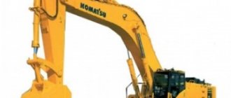
Universal single-bucket excavators are divided into:
in accordance with the drive of movement and the drive of working bodies - hydraulic, mechanical and electromechanical; in accordance with the type of support chassis - tracked or pneumatic wheels; in accordance with the volume of the bucket - buckets with a volume of 0.2-0.5 m3, 0.5-5 m3; in accordance with the installation method of the working body - with a flexible rope suspension or a rigid suspension, using hydraulic cylinders; in accordance with the design of the working bodies - with articulated or telescopic arms.
The main criteria used when choosing excavators:
height and depth of development; radius of the working area; vehicle loading height; The most widespread on construction sites and in quarries are excavators with a bucket with a volume of 0.15 to 4.5 m 3 with a hydraulic drive of working parts and a hydraulic drive of movement.
Single-bucket excavators can be equipped with various types of working parts: a bucket installed in the form of a front and backhoe, a grab, a hydraulic hammer, a tong grip, and a crane-type hook. These attachments are designed for universal use of the excavator, and therefore for more efficient operation of it as a piece of equipment.
A single-bucket excavator equipped with a special narrow bucket. It is an indispensable tool for digging narrow trenches and ditches for laying communications. The grab, as a mounted working element, is used for loading large volumes of bulk materials into a vehicle. A two or more bladed grab with a volume of 0.35-2.5 m 3 is also used for excavating soil from vertical holes. Using a mounted hydraulic hammer, monolithic pieces of rock are destroyed before loading.
The pincer gripper is used for loading non-destructible monolithic pieces and large piece goods. Hook suspension is used for hanging and transporting transport containers with various cargo. Sequence of elements of the excavator operating cycle. Development of soil (rock) and filling of the bucket. Raising a bucket with a load to a certain height. Rotate a loaded excavator bucket into a dump position over a dump or vehicle and release the load. Turn the excavator back into the working area.
Backhoe loader catalog
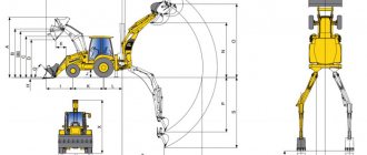
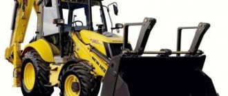
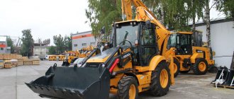
Backhoe loaders, or backhoe loaders, are machines that combine the functions of two types of equipment at once - an excavator and a loader. Their main purpose is to perform relatively small volumes of excavation and loading work combined with the need for frequent movements between work sites. Due to their versatility, backhoe loaders are widely used in construction and public utilities.
With the help of front equipment, backhoe loaders carry out loading and unloading operations with soil, which is mined with a backhoe. Loading equipment can also be used to perform surface leveling, backfilling of trenches, and other operations with soil above the machine parking level.
Excavator equipment is used to perform small-scale earthmoving work, digging trenches, pits, extracting and loading soil into vehicles. The backhoe bucket allows you to work only below the machine's supporting surface.
When transporting cargo, excavator equipment also acts as a counterweight, preventing backhoe loaders from longitudinally tipping towards the loading bucket.
JCB and Case are considered pioneers in the production of backhoe loaders. Case released a wheeled tractor, on which a backhoe was factory-mounted at the rear and a loading bucket at the front, in 1957. In the 50s of the last century, the British company JCB, which was the first to produce backhoe loaders, also worked on a new type of equipment. .
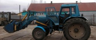
Foreign-made backhoe loaders were initially based on conventional wheeled tractors, but this practice was quickly abandoned. Currently, foreign manufacturers have switched to the production of complete vehicles, including base chassis. Domestic companies still produce backhoe loaders based on wheeled agricultural tractors.
To increase maneuverability and cross-country ability, modern backhoe loaders can be produced with the same wheels, an articulated frame and the ability to move in three ways - wheels of the same axle, “track to trail”, “crab motion”.
Another type of universal equipment is excavator bulldozers with a bulldozer blade mounted at the front. The blade is used to level construction sites and dirt roads, backfill trenches, etc.
Repeating the cycle.
The main time of the working cycle (up to 70%) is taken up by the turning time (there and back), which must be taken into account when calculating the productivity of the unit. The most used working part of an excavator is a bucket-straight shovel with a volume of 0.15 to 2.5 m3, the top of which is open and the leading edge is cutting. Using a lever system, the bucket can be rotated in a vertical plane, which ensures its loading and unloading.
The backhoe is used for digging trenches and pits up to 6 meters deep. All modern excavators are equipped with a hydraulic control system for working bodies and a hydraulic drive, which ensures that the unit operates with maximum effort with minimal dimensions of their drives. How does a single-bucket excavator work? (see picture)
The main components of a modern excavator are: the undercarriage, the unit platform, the platform rotation mechanism, the power plant—the engine, the control cabin, the boom, the handle, the bucket, the hydraulic cylinders—the bucket, the booms, and the handles.
The undercarriage is a welded support frame equipped with a caterpillar undercarriage. The tracks are of increased width, rest on rollers mounted on the frame, the front sprockets are tensioned, the rear sprockets are driven. The movement is driven by hydraulic motors, which receive operating oil pressure from a common hydraulic system.
On the upper part of the support frame of the undercarriage, there is a rotating shoulder strap that supports the rotating platform and, with the help of a hydraulic motor and gear transmission, ensures its rotation by 360°.
The control cabin, installed on a rotating platform, contains controls for the working bodies and the movement of the excavator, which are hydraulic distributors, control devices and a convenient place for the driver-operator. The boom, the main load-bearing working body, is a welded beam, hinged at the rear on a rotating platform. On the front part of the boom there is a hinged handle—a double-armed lever, pivotally connected to a bucket, which is a removable working body.
The boom handle and bucket are driven by paired double-acting hydraulic cylinders. A power unit is installed on the turntable - a diesel engine, from which the hydraulic system pumps receive torque. Working bodies control system.
The excavator control system is a complex of units that contains:
hydraulic tank with pumps, manually operated hydraulic distributors, rigid pipes and high pressure hoses.
There are two types of single-bucket excavators used in construction: full-rotary and part-rotary. A full-rotary single-bucket excavator (Fig. 7.1) consists of the following main parts: running equipment, a slewing bearing, a rotating platform with mechanisms and a power unit installed on it, and working equipment. For construction excavators, the running equipment can be tracked or pneumatic-wheeled.
Full-rotary construction excavators have several types of replaceable working equipment: forward and reverse shovels, draglines, grabs, hooks, etc. A straight shovel excavates the soil above the excavator parking level, and a reverse shovel - below the parking level. The working equipment consists of a boom, a handle, a bucket, which is rigidly or pivotally connected to the handle.
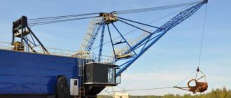
Draglines are used when developing soil below the excavator parking level. It is equipped with a long lattice boom and a scoop type bucket with a flexible connection to the boom. This design of working equipment provides larger digging and unloading radii than with a backhoe.
An excavator equipped with a grab is used to dig out deep pits and wells. The grab bucket consists of two hinged jaws. Excavator crane equipment is used for various loading, unloading and installation work.
Rice. 7.2. Single-bucket part-rotary hydraulic excavator: 1 - blade; 2 - tractor; 3 — boom control hydraulic cylinder; 4 — hydraulic cylinder for controlling the handle; 5 — handle; 6 — hydraulic cylinder for bucket control; 7 - ladle; 8 - boom; 9 — rotary column; 10 — outrigger.
The power plant of the excavator can be diesel, electric, diesel-electric and diesel-hydraulic. The working equipment is controlled using ropes and blocks (rope-block control system) or power hydraulic cylinders (hydraulic control system).
Partial rotation (Fig. 7.2) small excavators based on tractors are made.
Multi-bucket excavators are used for digging trenches, pits, and excavations. According to the design scheme, they are chain and rotary for longitudinal and transverse digging.
A chain longitudinal excavator (Fig. 7.3, a) is a self-propelled earth-moving machine consisting of a frame, engine, running equipment, working body and transverse belt conveyor. The working body consists of a frame, at the ends of which drive sprockets, tension rollers and two endless chains are installed, to which the buckets are attached.
The working process consists of cutting off soil chips with moving buckets. With the simultaneous forward movement of the excavator, the buckets are filled with soil, after which they are unloaded onto a transverse conveyor and the soil is dumped to one side or the other of the trench.
A rotary longitudinal excavator (Fig. 7.3, b) develops soil with buckets mounted on a rotor, which, by means of a frame, is attached to a boom suspended from the excavator frame and can move in a vertical plane. The process of digging a trench with a bucket wheel excavator is the same as with a chain excavator.
Rice. 7.3. Schemes of multi-bucket longitudinal digging excavators: a - chain; b - rotary; 1—belt conveyor; 2— arrow; 3 — stripping shoe; 4— ladle; 5 — rotor frame; 6 - rotor; 7 — running equipment; 8 — engine; 9— mechanism for lifting the working body; 10 — rotor drive.
The hydraulic control circuit is shown in the figure (see diagram) and works as follows:
The hydraulic circuit is functionally divided into two control units for hydraulic cylinders and hydraulic motors for turning the platform and driving the excavator and hydraulic cylinders for moving the working parts. The hydraulic system is equipped with a dual pump 2 with a power regulator, which is designed to adjust the pump flow depending on the external load, because when the working force on the working body increases, its speed decreases, and with a decrease in force, it increases, while the power must remain constant.
From the first block of the pump 2, the working fluid—oil—is supplied to the three-spool block of hydraulic distributors 4, which control the hydraulic cylinders of the outriggers 7 (for excavators on pneumatic wheels), the hydraulic motor for turning the platform 8, and the hydraulic motor for driving the excavator 9. A safety valve is built into this section. ensuring oil drainage when the pressure rises above the permissible level. The rodless cavity of the hydraulic cylinder 7, with the hydraulic spool in the neutral position, is locked with a hydraulic lock 6, which does not allow the unit to lower due to oil leaks from the system.
Valve 5 is attached to the hydraulic spool assemblies that control hydraulic motors 8 and 9, which ensures smooth beginning and end of movement of the controlled element. From the second section of pump 2, oil is supplied to the spool block 13, which controls the stroke of the second hydraulic motor 9, the hydraulic cylinders of the boom 10, bucket 14 and handle 12. When all the spools of block 4 are in the neutral position, under the action of the return springs, oil is under pressure from the first section pump 2, enters through the hydraulic spool block 4 into the hydraulic spool block 13, increasing the speed of the working bodies controlled by this block.
Between the second and fourth hydraulic spools of block 13, another spool is installed, which, when turned on at the same time, ensures the combination of movements of the handle, bucket, boom and rotation of the platform. Valve blocks 5 ensure smooth operation at the beginning and end of the movement of the working bodies. The speed of movement of all working parts is adjusted using throttles, and the cleanliness of the oil is ensured by the presence of filters. Auxiliary pump 14 is designed to fill the system with oil through a cleaning filter. The hydraulic system is equipped with pressure gauges and a thermometer to monitor the condition of the oil.
Modern excavators combine high productivity, low specific energy consumption, versatility, high specific power, and a high level of automation, which makes them irreplaceable in any type of construction work and in the extraction of ore materials.
