The clutch of a KamAZ vehicle consists of a mechanism and a drive and has the following design features:
- The clutch mechanism has a device for automatically setting the middle drive disk to the middle position when the clutch is disengaged. This device does not require adjustment during operation;
- the shape of the casing ensures fixation of the pressure springs;
- the driven disc has a heat-resistant friction lining with a long service life;
- the clutch pedal is suspended, which does not violate the seal of the cabin, and the metal-plastic bushings in the pedal supports do not require replenishment of lubricant.
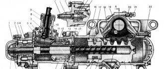
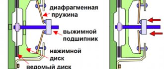
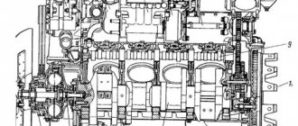
The clutch mechanism (Fig. 122) consists of a housing 20, a pressure plate 4 with a casing 17, pressure springs 16 and release levers 6′, two driven disks 1 with friction linings 22 and torsional vibration dampers; middle drive disk 2.
The stamped clutch housing 17 is installed on the flywheel using two mounting sleeves 3 and secured with ten M10 and two M8 bolts.
The drive disks, pressure 4 and middle 2, each have four spikes on their outer surfaces, which fit into special grooves in the flywheel and transmit engine torque to the friction surfaces of the driven disks, the hubs of which are installed on the splines of the drive shaft of the gearbox or divider.
Between the clutch housing 17 and the pressure plate 4 there are pressure springs 16, under the action of which the driven and middle drive disks are clamped between the pressure plate and the flywheel.
The middle drive disk 2 has a lever mechanism 27. It automatically sets disk 2 to the middle position when the KamAZ clutch .
The clutch release device consists of 4 pull-off levers balanced on the pressure plate with a thrust ring 14, a clutch release clutch 12 with a thrust bearing 10 mounted on the bearing cover of the drive shaft of the gearbox or divider, and a release fork 13 placed on a roller in the clutch housing (divider ).
Rice. 122. Clutch mechanism: 1 — driven disk; 2 — leading middle disk; 3 — installation sleeve; 4 — pressure disk; 5 — release lever fork; 6 — release lever; 7 — thrust ring spring; 8 — coupling lubrication hose; 9 — spring loop; 10 — release bearing; 11 — release spring; 12 — clutch release; 13 — clutch release fork; 14 - thrust ring; 15 — fork shaft; 16 — external pressure spring; 17 — clutch casing; 18 — heat-insulating washer; 19 — casing mounting bolt; 20 — clutch housing; 21 - flywheel; 22 — friction lining; 23 — internal pressure spring; 24 - input shaft; 25 — torsional vibration damper disk; 26 — internal spring of the torsional vibration damper; 27 — external spring of torsional vibration damper; 8 — driven disk ring; 29 - mechanism for automatically adjusting the position of the middle drive disk
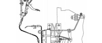
The clutch drive (Fig. 123) consists of clutch pedal 1 with release spring 11, master cylinder 2, compensation tank 5 with working fluid, pneumatic-hydraulic booster 18 pipelines and hoses for supplying working fluid from the master cylinder to the clutch booster and air supply from the pneumatic system to the clutch booster.
The pneumohydraulic drive booster serves to reduce the force on the clutch pedal. It is secured with two bolts to the clutch housing flange (divider) on the right side of the power unit. When you press the clutch pedal, the fluid pressure from the master cylinder is transmitted through pipelines and hoses to the clutch pneumatic booster to the hydraulic piston and to the piston of the follower device, which automatically changes the air pressure in the power pneumatic cylinder of the booster in proportion to the force on the clutch pedal.
During operation, as the linings of the driven discs wear out, the clutch drive should be adjusted to ensure free movement of the clutch release clutch.
- Clutch maintenance and repair
Rice. 123. Clutch mechanism drive: 1 - pedal; 2 — main cylinder; 3, 10 — lower and upper stops; 4 — bracket; 5 — compensation tank; 6 — hydraulic pipeline; 7 — lever; 8 — piston pusher; 9 — eccentric finger; 11 — tension spring; 12 - plug; 13 - pipeline; 14 — air release valve; 15 — spherical adjusting nut; 16 — pneumatic hydraulic booster piston pusher; 17 — protective cover; 18 — pneumatic hydraulic booster; I-compressed air
Rice. 124. Pneumatic booster: 1 - spherical nut: 2 - lock nut; 3 — clutch release piston pusher: 4 — protective cover: 5 — clutch release piston; 6 — follower piston body: 7, 21, 24, 26 — cuffs; 8 — bypass valve; 9 — breather; 10 — membrane of the tracking device; 11 — membrane seat; 12 — plug: 13 — return spring; 14 — air supply cover; 15 — valve stem; 16 — inlet valve; 17 — exhaust valve; 18, 22 — membrane and piston springs; 19 — front body; 20 — pneumatic piston; 23 — piston seal housing; 25 — spacer spring; 27 — rear body; I — brake fluid supply; II - air supply
KamAZ clutch
The leading parts of the clutch are flywheel 1, the middle drive disk 12, the pressure plate 11 and the casing 10, and the driven ones are disks 3 with dampers 2 of torsional vibrations. The force compressing the drive and driven disks is created by springs 9. Torque from the engine is transmitted to the pressure and middle drive disks through protrusions made on their outer surfaces, which fit into four longitudinal grooves on the flywheel.
Diagram 1 – Clutch (a) and clutch drive (b) of KamAZ trucks
1 – flywheel; 2 – damper; 3 – driven disks; 4 – lever mechanism; 5 – lever; 6 – bearing; 7 – coupling; 8 – ring; 9 – spring; 10 – casing; 11 – pressure disk; 12 – drive disk; 13, 16 – levers; 14 – pedal; 15, 23 – cylinders; 17, 22 – rods; 18 – pipeline; 19 – pneumatic booster; 20 – tracking device; 21 – air duct
The grooves on the flywheel allow the protrusions, and therefore the disks 11 and 12, to move relative to the flywheel when the clutch is engaged and disengaged.
A lever mechanism is installed on the middle drive disk 12 , the spring of which, when the clutch is disengaged, turns the equal-arm lever 13. In this case, the lever, resting its ends against the pressure plate 11 and the flywheel 1, sets the middle drive disk 12 at the same distance from the flywheel and the pressure plate.
The clutch release levers 5 are connected to a thrust ring 8, against which, when the clutch is disengaged, the release bearing 6 of the release clutch 7 rests, moving along the guide sleeve.
KamAZ clutch drive device
The clutch drive is hydraulic with a pneumatic booster. The drive includes (diagram 1, b) a pedal 14, a main cylinder 15, a working cylinder 23, a pneumatic amplifier 19, a follower device 20, a fork and a release clutch with a bearing, pipelines 18 and hoses for supplying working fluid from the main cylinder to the working one, as well as air duct 21 for supplying air to the pneumatic amplifier.
When the clutch is disengaged, the force from the pedal 14 through the lever 16 and the rod 17 is transmitted to the piston of the main cylinder 15, from which the working fluid under pressure through the pipeline 18 simultaneously enters the working cylinder 23 and into the housing of the follower device 20. The follower device ensures that compressed air enters the pneumatic booster 19 from air line 21. It automatically changes the air pressure in the pneumatic booster in proportion to the force on the clutch pedal. The total force created by the air pressure in the pneumatic booster 19 and the fluid pressure in the working cylinder 23 is transmitted through the rod 22 to the clutch release fork and from it to the release clutch with a release bearing.
Installing a pneumatic booster in a hydraulic drive makes it much easier to control the clutch - disengaging it and holding it in the disengaged position. If the pneumatic booster fails, the clutch is released only by fluid pressure. In this case, the force of pressing the clutch pedal increases to 600 N.
Drive master cylinder
The master cylinder of the clutch drive (diagram 2) includes a housing 3, a piston 5 with a rod 6, a sealing collar 4 and a return spring 2. Inside the housing there are cavities A and B, which are filled with working fluid. The cylinder body is closed with a protective cover 7 and a plug 1 with a threaded hole for connecting the pipeline.
Diagram 2 – Master cylinder of the clutch drive of KamAZ trucks
1 – plug; 2 – spring; 3 – body; 4 – cuff; 5 – piston; 6 – rod; 7 – cover; A, B – cavities; B – hole
MAZ double-disc clutch
MAZ trucks (diagram 4), compression of the flywheel 1, pressure 18, middle drive 3 and two driven 2 disks is carried out by peripheral coil springs 16, evenly spaced in two rows around the circumference. Each row includes 14 springs.
Diagram 4 – Clutch of MAZ trucks
1 – flywheel; 2 – driven disks; 3 – drive disk; 4, 14 – rings; 5, 6, 16 – springs; 7 – rod; 8, 17 – covers; 9 – lever; 10 – fork; 11 – nut; 12 – crankcase; 13 – bearing; 15 – casing; 18 – pressure plate
The driven disks include torsional vibration dampers, each of which has six cylindrical springs 5 and two steel friction rings 4. The middle drive and pressure disks with guide protrusions fit into the grooves of the flywheel, the springs 6 are located between the flywheel and the middle disk. When the clutch is released, they move the middle disk to the required amount, which is adjusted by four rods 7. Four clutch release levers 9 are installed in forks 10, secured in the casing 15 with spherical nuts 11.
to the inner ends of the levers , into which the release bearing 13 of the release clutch rests when the clutch is disengaged. The coupling and bearing are lubricated through a flexible hose from an oiler attached to the housing 12. In the upper and lower parts of the clutch housing there are hatches with covers 8 and 17. The lower cover 17 has ventilation holes.
Design features
As a rule, KamAZ vehicles are equipped with a dry double-disc (in rare cases single-disc) friction-type clutch. This device is common in almost all heavy, high-power machines. It requires constant maintenance due to the fact that during operation, due to the great power of the vehicles, these clutches experience enormous loads. So, in what cases does it become necessary to adjust the clutch of MAZ and KamAZ:
- The device clearly slips at high speeds.
- The pedal free play does not meet the standard values.
- A mechanical noise occurs when changing gears.
Not available:
| № | Part code | Name | Part Information |
| 5297-1602518 | Clutch master cylinder spring | Quantity 1 Model 5297 Group Clutch Subgroup Pedal and clutch control drive Part serial number 518 | Not available |
| 5320-1602513-10 | Clutch master cylinder | Quantity 1 Model 5320 Group Clutch Subgroup Pedal and clutch control drive Serial number of part 513 Additionally Not interchangeable with a part previously released under the same number | Not available |
| 5320-1602529 | Clutch master cylinder plug | Quantity 1 Model 5320 Group Clutch Subgroup Pedal and clutch control drive Part number 529 | Not available |
| 5320-1602531 | Clutch master cylinder plug gasket | Quantity 1 Model 5320 Group Clutch Subgroup Pedal and clutch control drive Part serial number 531 | Not available |
| 5320-1602543 | Master cylinder protective cover | Quantity 1 Model 5320 Group Clutch Subgroup Pedal and clutch control drive Part number 543 | Not available |
| 5320-1602553 | Union | Quantity 1 Model 5320 Group Clutch Subgroup Pedal and clutch control drive Part number 553 | Not available |
| 5320-1602575 | Flexible hose | Quantity 1 Model 5320 Group Clutch Subgroup Pedal and clutch control drive Part serial number 575 | Not available |
| 864300 | Traffic jam | Quantity 1 Coated uncoated | Not available |
How to know when it's time to change your clutch
There are cases when adjusting the clutch cannot correct the problem. Perhaps you missed a moment when you could get by with little effort, or maybe the device failed for some objective reason. So, it’s time to change the MAZ clutch if you notice the following signs:
- The device turns on abruptly, the car jerks and abruptly pulls away.
- Noise in the mechanism, perhaps a loud cracking sound when the gear is engaged.
- The car starts moving late, even if you release the clutch on time.
- A characteristic burning smell in the cabin (this is a clear sign that the clutch has burned out).