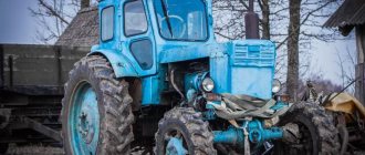
MTZ 82 tractor diagram
The MTZ 82 tractor is made according to the usual, standard design, like most other tractors (the rear wheels are naturally larger than the front ones) and they have a semi-frame design.
Most often, the tractor is equipped with diesel D 240 with start from an electric starter or MTZ-82 240L with start, which already comes from a carburetor starting engine. A diesel engine with natural injection of fuel and volumetric film mixture formation in the combustion chamber, which is located in the piston, develops power up to approximately 59 kW (80 hp) at a rotation speed of about 2200 min and a very low fuel consumption of 238 g/kWh ( 185 g/e.hp.h).
Cabin heater MTZ: heater radiator
The tractor cabin heater is indispensable in the winter season. With the help of this small-sized device, a comfortable temperature, optimal for driving, is always maintained in the tractor interior.
How does the MTZ cabin stove work?
At low temperatures, the heater uses hot water. The device itself is located in the cabin on the right - it is mounted directly to the floor.
In the device of the stove, it is worth highlighting several main components. This is a radiator for the MTZ stove (with lower and upper connections for attaching hoses) and an electric motor with a fan. During the working interaction of these components, heated air is directed to the window of the tractor cab.
For the MTZ stove to function, water is required, which flows to the radiator through hoses. After cooling, the liquid is discharged to the engine. In some models of agricultural machinery (for example, the Belarus tractor), the liquid supply is carried out from a thermostat.
For the cabin heater of agricultural machinery, a separate start of its electric engine is provided. Thus, the unit begins to operate when the switch is pressed. The lever is placed either in the right/left position (electric motor on) or in the middle position (electric motor off).
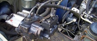
Design and principle of operation of the generator
Before finding out the size of the alternator belt, it is necessary to study this element, its design and operating principle in more detail. Despite the fact that different types of generators were installed on MTZ tractors, they are absolutely identical in their performance indicators and features.
This element has an identification number, which may vary and depends on the modification used:
For its correct operation, a necessary requirement is the presence of direct current. The design of the generator involves the passage of current through a three-phase rectifier, which allows it to be transformed from alternating to direct.
The characteristics of the generator are determined by the operation of its main elements, which are the stator and rotor. The first is made from sheet steel, as well as a three-phase coil mounted on a special protrusion. The rotor is a star-shaped element with 6 angles, mounted on a shaft. The principle of operation is extremely simple: using a V-belt, the rotation of the crankshaft is transmitted to the generator pulley. Due to the rotational movements of the rotor mechanism, an electromagnetic field is created, which, under the action of the windings, leads to the appearance of a current passing through the rectifier.
Essential elements
When planning to buy a generator at MTZ 82 for its subsequent installation, you need to familiarize yourself with its design in more detail. As mentioned earlier, its basis is the stator and rotor, but there are many other elements that ensure the correct operation of the unit. Among them, worthy of mention:
- front, rear cover, and regulator protection;
- rectifier, insulator, coil and fan;
- adjusting and fastening elements;
- rotor and spacer bushings.
Knowing what elements the design of such a device consists of, it will be much easier for the owner of an MTZ tractor to install it themselves or carry out repairs, which will reduce the cost of specialist services.
Important Review of the DT-75 tractor and its modifications
How to connect an MTZ stove
Tractor cabin heating and ventilation system
The system is designed to create a microclimate in the cabin in accordance with the requirements when working in both hot and cold weather. It consists of two fans (Fig. 125) with ME-226B electric motors, two radiators (Fig. 126), a shut-off valve (Fig. 127) and two drain valves, connecting hoses with connecting fittings, an air distribution system (see Fig. 125) , two recirculation dampers, cardboard filter.
Rice. 124. Seat: 1 — seat cushion; 2 — armrest; 3 - back; 4 — handle for locking the seat tilt in the transverse plane; 5 — handle for adjusting the seat height (driver’s weight); 6 — seat frame; 7 — shock absorber; 8 — seat back tilt latch handle; 9 — lever for locking the seat position in the horizontal direction.
Promotional offers based on your interests:
Rice. 125. Cabin ventilation and heating system: 1 - fan with electric motor; 2 — air distributor; 3 - recirculation damper; 4 - filter.
Rice. 126. Radiator of the ventilation and heating system: 1 - radiator core; 2 — tank pipes; 3 — radiator tank.
The heater radiators (see Fig. 126), fans (see Fig. 125) and a cardboard filter are assembled into a single unit installed in the front part of the cab under the roof.
The heating and ventilation system is controlled using a key switch for the fan motors, a shut-off valve (see Fig. 127) and two recirculation dampers (see Fig. 125) located on the inner roof panel.
To operate the system in heating mode, the valve (see; Fig. 127), located at the rear end of the diesel cylinder head, is opened. The air flow entering the cabin is controlled by turning on one or two fans, as well as by turning the recirculation flaps. When the heater is turned on, the flow of warm air into the cabin begins 5... 10 minutes after the start of diesel operation.
Rice. 127. Connection diagram of the heater to the diesel cooling system: 1 - shut-off valve; 2 — connecting hoses; 3 - drain valve.
To operate the system in ventilation mode, it is necessary to stop the flow of heated liquid from the diesel cooling system into the heater radiators by turning off the valve.
When operating the system, the following conditions must be met: 1. After filling the cooling system with liquid, the diesel engine is put into operation; the KR-29 valve on the head of the diesel engine block is not opened for a period of time that allows the liquid in the cooling system to be warmed up to 50...60°C. Opening the tap while the diesel engine is running causes the heating system radiators to fill with liquid. 2. Add liquid to the cooling system to a level 50 mm below the upper edge of the filler neck. 3. The cabin warms up with the recirculation dampers open, which can be closed during further operation. 4. Water from the cooling system is drained through the drain valves of the diesel cylinder block and radiator with the heater drain valve plugs removed (the KR-29 valve must be open). 5. After draining the water from the heating system, close the KR-29 tap. 6. When working in conditions requiring cabin ventilation, the KR-29 valve must always be closed.
PROCEDURE FOR DIAGNOSTICS OF MTZ GENERATOR
- Check the tension of the generator belt. If the tension is insufficient, the belt may slip under load and not provide the generator with sufficient rotation speed.
- Connect the “minus” from the battery to the “M” terminal, and the “plus” to the “B” terminal. If the battery charge indicator light is on, this means that the rectifier is faulty (short circuit of diodes, insulation breakdown, short circuit of the positive terminal to the generator housing).
- Connect the “minus” from the battery to one of the AC terminals, and the “plus” of the battery to the “B” terminal of the generator. The control lamp should not light up. If the lamp is on, the straight polarity rectifier diode (or several) is broken.
- Connect the “plus” from the battery through a test lamp to one of the alternating current terminals of the generator, and the “minus” of the battery to the “M” terminal. If the control lamp is lit, this indicates that the reverse polarity rectifier diode (or several) is broken, or there is a short circuit of the stator winding to the generator housing.
Table of technical characteristics of MTZ generators (D-240)
| Technical characteristics of models installed on MTZ tractors | |||||||||
| Type | Rated power, W | Rated voltage, V | Maximum current load, A | Rated rotation speed, Rpm | Maximum excitation frequency, RPM | Applicability with engines | Applicability by model | Weight, kg | |
| With battery | Without battery | ||||||||
| G460.3701 (-1) G4607.3701 | 700 | 14 | 50 | 5000 | 1450 | 1650 | D-50, D-65 | MTZ-50 | 6,3 |
| G464.3701 (-1) | 700 | 14 | 50 | 5000 | 1450 | 1650 | D-245 | MTZ-80/82 | 6,2 |
| Г468.3701 (-1) | 700 | 14 | 50 | 5000 | 1450 | 1650 | D-245 | MTZ-100, 102, 1021, 1022, 520/522, 592 | 6,7 |
| G964.3701 (-1) G9647.3701 (-1) | 1000 | 14 | 72 | 4500 | 1250 | 1250 | D-260, D-245.5, D-245.7 | MTZ-80/82, 1221 | 6,3 |
| G994.3701 (-1) G9947.3701 (-1) | 1000 | 28 | 36 | 4500 | 1250 | 1250 | D-260, D-245 | MTZ-1221 | 6,3 |
| G9702.3701 | 1400 | 14 | 100 | 7000 | 1400 | 1400 | D-245, D-260 | MTZ-80/82, 102, 520/522 | 7,3 |
Finally we got around to the generator from the MTZ tractor, which had been lying on the shelf at work for the 2nd month and was waiting in the wings) MTZ-82 generator, power 1 kW.
Among the modifications: relocation of the relay-regulator and capacitor, which rest against the engine mount
manufacturing an adapter for the standard tensioner bracket and a bushing for the generator mounting bracket
Important The best Grimme potato harvesters: owner reviews, technical specifications, price
Among the shortcomings: you need to pick up a pulley... the original generator is a little larger than the standard Nivsky one - undercharging at idle ((Confidently holds the voltage only from 1300 rpm... but these are trifles)
Fuses and relays for the Belarus MTZ-82.1 tractor
Electrical fuses are designed to protect against overloads and short circuits in electrical circuits.
Molded Panel Instrument Fuses
Three fuse blocks for electrical circuits are mounted in the instrument panel with a molded panel. To access the fuses located in the instrument panel of the Belarus MTZ-82.1, 80.1, 82.2 tractor, you need to unscrew screw 2 and fold back panel 3.
Rice. 1 - Access to fuses located in the instrument panel with molded panel
1 – instrument panel; 2 – screw; 3 – panel.
Rice. 2 - Fuses located in the instrument panel with molded panel
Purpose of instrument panel fuses with molded panel
1 - 15A - Brake lights, terminal (6) and terminal (8) trailer socket. 2 - 15A - Road train sign lights (if equipped), rear work lights, cabin lighting. 3 - 15A - Hazard warning lights. 4 - 25A - Front and rear windshield wipers, front window washer. 5 - 15A - Sound signal. 6 - 25A - Main beam of road headlights, signal lamp for turning on the main beam of headlights. 7 - 25A - Front working lights, signal beacon (when installed). 8 - 25A - Power supply for the heater fan control circuit or power supply for the heater fan 80-8101720. 9 - 25A - Power supply for consumers operating when the starter switch and devices are in the "devices on" position: devices, speed sensors, power supply to fuse 15 and 16. 10 - 25A - Power supply for the electric motor of the fan-heater (when installing the fan-heater 80- 8101720 this fuse is not used); 11 - 7.5A - Left side parking lights, trailer socket terminal (7), license plate lighting. 12 - 15A - Side lights on the starboard side, terminal (5) of the trailer socket, instrument lighting. 13 - 7.5A - Low beam of the left road headlight. 14 - 7.5A - Low beam of the right road headlight. 15 - 7.5A - Power supply for instruments, speed sensors, warning lamp units, emergency sound alarm (buzzer) and parking brake relay breaker. 16 - 15A - Turn signal relay, glow plug block, glow plug relay coils.
Molded Panel Instrument Fuses
Three fuse blocks for electrical circuits are mounted in the instrument panel with a molded panel (installed upon request to replace the panel with a molded panel). To access the fuses, unscrew two screws 2 and open the cover of the instrument panel 1.
Rice. 3 -. Location of fuse boxes in a molded panel instrument panel
1 – instrument panel cover; 2 – screw.
Rice. 4 — Placement of fuses in the instrument panel Belarus MTZ-82-1, 80-1, 82-2 with a molded panel
Assignment of molded panel instrument fuses
1 - 15A - Brake lights, terminal (6) and terminal (8) trailer socket. 2 - 15A - Road train sign lights (if equipped), rear work lights, cabin lighting. 3 - 15A - Hazard warning lights. 4 - 25A - Front and rear windshield wipers, front window washer. 5 - 15A - Sound signal. 6 - 25A - Main beam of road headlights, signal lamp for turning on the main beam of headlights. 7 - 25A - Front working lights on the roof, signal beacon, working lights on the handrails (if equipped). 8 - 25A - Power supply for the heater fan control circuit or power supply for the heater fan 80-8101720. 9 - 25A - Power supply for consumers operating when the starter switch and devices are in the "devices on" position: devices, speed sensors, power supply to fuse 15 and 16. 10 - 25A - Power supply for the fan-heater (when installing the fan-heater 80-8101720 this fuse is not used); 11 - 7.5A - Left side parking lights, trailer socket terminal (7), license plate lighting. 12 - 15A - Side lights on the starboard side, terminal (5) of the trailer socket, instrument lighting. 13 - 7.5A - Low beam of the left road headlight. 14 - 7.5A - Low beam of the right road headlight. 15 - 7.5A - Instrumentation, warning lamp block, speed sensors, alarm sound alarm (buzzer). 16 - 15A - Power supply for the turn signal switch, power supply for the glow plug control system, glow plug relay coils.
Basic problems in engine starting systems
Any engine starting system for MTZ tractors requires maintenance, and in case of malfunction, repair.
There are several possible malfunctions of the electric starter:
- The starter does not turn on. If there is no doubt about the serviceability of the device itself, then you should look for the reasons in the electrical circuit of the tractor. The switch may be faulty or the wiring may be broken. It is necessary to check, if necessary, clean and tighten fasteners and terminals.
- When the starter is turned on, the engine cranks slowly. The reason may be insufficient battery charge or inappropriate oil for the season. The brush contacts may be broken. In this case, the starter is disassembled, the commutator is cleaned, the brushes are changed and the brush springs are adjusted.
- If the starter armature rotates, but does not turn the crankshaft. Most likely the freewheel is slipping. This leads to inevitable replacement of the starter drive.
- After starting the engine, the starter does not turn off. This may be a consequence of drive jamming, sintering of relay contacts, short circuits of relay winding turns, or bearing wear. In these situations, the starter must be removed to accurately determine the cause of the failure. If necessary, replace bearings, traction relay, etc.
- One of the common malfunctions is the lack of engagement of the starter bendix with the flywheel crown. Most often this is due to contamination of the Bendix mechanism itself, and is eliminated by washing it in gasoline. After that, you need to manually turn the gears and you can install them in place.
It is important to remember that the performance of the starter, like any other mechanism, depends on the prevention of malfunctions. Monthly maintenance periods have been established for MTZ tractors, which the owner must comply with.
As a result, the lifespan of all tractor systems will increase significantly
For MTZ tractors, monthly maintenance periods have been established that the owner must comply with. As a result, the lifespan of all tractor systems will increase significantly.
Steering tuning
Sometimes experts recommend carrying out work such as remaking the MTZ-82 steering, in other words, putting the steering column of an agricultural vehicle in order. Sometimes modifications to the MTZ-82 tractor steering column end with its adjustment so that the steering wheel is in a comfortable position.
However, for a number of craftsmen this does not end there; altering the steering makes working on the tractor more convenient. Remaking the MTZ steering column will require some skills and a fairly significant amount of time, but the result will exceed all expectations. The stove takes approximately the same time, namely the process of its conversion.
Important TOP 3 representatives from the Lynx brand chainsaw model range
The same applies to the modification of the turbocharger and the modernization of the MTZ-80 in terms of providing it with special nozzles for the dispenser.