Description of the types of instrument panels MTZ 82(80)
Over the course of more than forty years of production, the Belarus tractor has undergone a number of changes in the cabin interior due to the modernization of the machine and the improvement of the control system for the operation of mechanisms and components, as well as due to the improvement of the ergonomic qualities of the driver’s workplace.
Speaking about equipping the MTZ 80(82) with control and measuring sensors, it should be noted that the tractor, depending on the year of manufacture, is equipped with three versions of instrument panels, which are an integral part of the control system. Instrument panel MTZ 80.1
MTZ instrument panel - design and repair
MTZ instrument panels are mounted on tractors with a large or small cab. Usually they are equipped with blocks of warning lamps or fuses.
The instrument panel housing protects the equipment from moisture, dust, and mechanical influences.
Thus, electrical circuits operate properly even under heavy loads on agricultural fields.
The shield is very durable. It is made of durable plastic and includes metal inserts. Weighs no more than eight kilograms and installs quickly.
In this figure you can study in detail the design of the MTZ instrument panel.
The durable shield includes the following mechanisms:
- Nuts (1, 4, 37, 32), brackets (3, 12, 23, 25, 35), washers (2, 5, 6, 33, 14);
- Cabin shield (39);
- Bolts (7, 15), screws (8, 22, 30, 34), harnesses (9, 10);
- Handbrake lamp relay (13), screw (16, 21), bracket (17);
- Alarm relay (19), plug (20), warning lamp block (24, 26);
- Instrument cluster KP-6 (27), MTZ tachometer speedometer (28), casing (29);
- Steering column switch (31), control panel (36);
- Starter switch (38), seal (40).
Most models of MTZ instrument panels contain:
- Voltage indicator.
We have placed the permissible values of this sensor in this table.
- Optimal fuel value indicator.
- Working fluid temperature sensor for the engine cooling system;
- Lamp blocks;
- Pressure meter;
- MTZ tachometer speedometer (here you will read about repair, installation and spare part design);
- Stub;
- PU tachospeedometer.
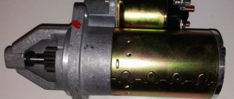
In the instrument panel of the MTZ 80 or other tractor models, three electrical circuit fuses are installed that protect the sound signal, hazard warning lights, windshield washer, side lights and other circuits from overvoltage.
A 60A fuse is also provided to protect the battery circuit.
Advice - try to avoid burning electrical wiring.
Install only fuses recommended by the manufacturer in the tractor instrument panel and other systems.
Do not buy parts with a higher amperage rating, otherwise it will often fail.
Typically, tractor instrument panels last a long time. If you use the part correctly, there should be no scratches, chips or cracks.
The only thing is that the system power buttons may get stuck. Also, in some cases, the MTZ tachometer speedometer malfunctions, showing incorrect values (you can read more about the MTZ tachometer speedometer and its operation here).
In any case, we advise the lido to repair the shield or buy a new one.
In our catalog you will find high-quality tractor instrument panels from the Belarusian manufacturer at the best prices.
Our catalog contains spare parts for both small and large cabins. If desired, it is easy to order an assembled MTZ instrument panel.
Old style panel
This instrument panel (with catalog article 70L-3801010 for a tractor with a starter and 70-3801010 with a starter) has been installed since 1974 on the MTZ 80(82) with a small cabin. The unit is a sheet metal housing with an opening for the steering axis.
Old instrument panel of the MTZ 80 tractor
In the front part, on a small inclined plane, separate mechanical type indicator sensors are located from left to right:
- coolant temperature UK133-V
- ammeter AP110
- air pressure in the MD 226 pneumatic system
- oil pressure in the MD 219 engine
- tachospeedometer TX-135
- Additionally, a fuel level sensor in the tank UB 126 is attached to a separate bracket on the right side.
Tachometer speedometer TX 135 Air pressure sensor MD 226 Oil pressure sensor MD 219 Coolant temperature sensor UK 133V Ammeter AP 110 Fuel level sensor UB 126
On a large horizontal area there is a row of colored warning lamps, covered with a shield in the position from left to right:
Behind the lamps, closer to the driver, there is a row of switches:
- toggle switch for high and low beam
- turn signal toggle switch
- horn button
On the right side of the steering wheel seats are located:
- element PD 50V(20) for monitoring the degree of heating of the coil of an electric torch heater
- starter control switch (23).
In the rear end part of the shield, under the cover, there is a fuse block for the tractor electrical system and a handle for the headlight mode switch.
Today, analogues of this panel are produced by various manufacturers, which may differ in the additional equipment of an emergency stop button and an electric cigarette lighter wick.
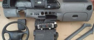
Controls and instruments of the MTZ-82 tractor
The location of the controls for the Belarus MTZ-82 tractor is shown in Fig. 1.
1 — diesel engine stop and emergency stop handle. When you pull the handle toward you, the fuel supply to the cylinders stops and the diesel engine stalls. When released, the handle returns to its original position under the influence of a spring.
2 — control handle for the cabin heater valve (if installed).
3 — differential lock control handle (for Belarus MTZ-82 tractors with power steering housing); has three positions: I “blocking off”, II “automatic blocking”, III “forced blocking”.
4 — handwheel for controlling the water radiator shutter. When the handwheel rotates clockwise, the curtain rises; when rotated counterclockwise, it lowers. When the curtain is lowered, the temperature of the diesel engine decreases.
5 — rear axle differential lock pedal. When you press the pedal all the way, the lock is turned on, when you remove your foot from the pedal, it turns off.
6 - switch for starting aids (EFS).
7 — windshield washer switch.
8 - light switch. It has two positions: I — instrument lighting and side lights are on; II - in addition to position I, road headlights are turned on.
9 — alarm switch.
17—switch for direction indicators, low and high beams, sound signal.
19 — radio receiver (optional).
20 — cover of the steering wheel height adjustment mechanism. To change the height, remove the cover, unscrew the wing nut 3-5 turns and set the required steering wheel height.
21 — front window wiper switch.
22 — cabin heater fan switch.
23 - switch for rear working lights.
24 - front working headlight switch.
24a—switch for the “Road Train” sign.
25—cabin light with switch.
26 — air distributor of the cabin ventilation and heating system.
Before you start working on the tractor, study the purpose of the controls, instruments and their functions.
27, 28, 29 — hydraulic system distributor control levers: 27 — left side terminals; 28 — right side terminals; 29 - rear terminals.
If the MTZ-82 tractor does not have a power regulator, then lever 29 controls the cylinder of the hitch, and lever 27 controls the left side and rear terminals duplicated with it. The connection diagram for the hydraulic system terminals is given on the instruction plate in the tractor cab.
Each lever has 4 positions: “floating”, “forced lowering”, “neutral”, “raising”. In the “forced lowering” position with the engine running, the lever should be held by hand.
30— tachometer speedometer control panel.
31 - starter and instrument switch. It has three positions (from neutral): I - power supply to devices; II - turning on the starter; position counterclockwise from neutral - the radio is on.
32 — lever for turning on the reduction gear. It has two positions: front - “Gearbox on” (slow movement of the tractor) and rear - “Gearbox off” (fast movement of the tractor).
In the Belarus MTZ-82 tractor with a synchronized reduction gearbox, the control lever 32 has two positions: rear - “Gearbox on” (slow movement of the tractor) and front - “Gearbox off” (accelerated movement of the tractor).
In a tractor with a synchronized reverse gearbox, control lever 32a (unlike lever 32 is bent to the left along the tractor) has two positions: rear - “Reverse on” and front - “Reverse off” (forward).
33 — connecting bar of the brake pedals for simultaneous braking with the right and left brakes.
34 — fuel control pedal.
35, 36 — brake pedals. When you press the pedals with your foot, the tractor slows down; at the same time, the brake valve of the pneumatic drive of the trailer brakes is activated from pedal 35. 37 — handle for fixing the tilt of the steering column.
38— clutch control pedal.
39 — gear shift lever. When moving the lever forward in the extreme left position, the 2nd (increased) gear range is switched on, and back - the 1st (lower) gear range.
40 — control lever for the attachment fixing mechanism. The extreme left position of the lever is “the hitch is fixed”, the extreme right is “the fixation is removed”. You must first raise the hitch to the top position.
41 — control lever for the transfer case of the MTZ-82 FDA drive. The middle position of the lever is “FDR is switched on automatically”, lower (pull) – “FDR is switched off”, upper (pull) – “FDR is forcibly switched on”.
42 — parking brake control lever.
43 — lock of the power regulator control handle.
44 — fuel supply control handle. The extreme forward position is the maximum fuel supply, the rearmost position is the minimum supply corresponding to the minimum idle speed.
45 — power regulator control handle. The rearmost position of the handle is “raising the implement” (while lifting, hold the handle with your hand); after releasing the handle, it moves forward and is fixed in the “transport neutral” position. The intermediate position forward from the “transport neutral” position is the “regulatory zone”.
The extreme forward position of the handle is “forced lowering” (hold the handle with your hand). After releasing the handle, it returns back and is fixed at the leading edge of the control zone.
46 — rear PTO control lever. It has two positions: front - “PTO off”, rear - “PTO on”.
47 - battery ground switch.
48— seat back tilt lock.
49 — seat belt bolt
50 — lever for fixing the seat in the longitudinal plane. By moving the lever all the way up, the seat can be moved forward or backward.
51 — handle for adjusting the seat according to the operator’s weight. When the handle is rotated clockwise, it is adjusted to a larger mass, and counterclockwise, to a smaller one.
Seat height adjustment is carried out:
— to increase the height of the seat — by successively manually moving the seat up;
- to reduce the height - with a sharp lift, the seat moves up until it stops, then lowers (push down) to the lowest position, after which it rises up to the desired lower height.
52 - power (position) regulator switch. It has three positions: right - “positional regulation”, left – “force regulation”; middle - “off”.
53 - handwheel for controlling the speed of correction by the power regulator. When turning the handwheel clockwise, the correction speed decreases, and counterclockwise, it increases.
54 — hydraulic hook grip control handle. The lower position of the handle is “grips under load”, the upper position is “grips free from load”.
55 — handle for switching the rear PTO from independent to synchronous drive. When the handle is moved to the extreme left position (along the tractor's direction), the synchronous drive is activated; when the handle is moved to the extreme right, the independent drive is activated; the middle position is neutral.
56 - handle (Fig. 3) for turning on the compressor. It has two positions: left (arrow on the handle faces forward) - “compressor off”, right (arrow on the handle faces back) - “compressor on”. Turn on the compressor when the diesel engine is not running or at minimum idle speed.
57 — lever (Fig. 4) for turning on the hydraulic system pump. It has two positions: upper – “pump on”, lower – “pump off”. To move the lever, it must be released from fixation by pulling handle B.
58 — driver (Fig. 5) for switching the rotation speed of the rear independent PTO. When the driver is turned to position I, the 1st stage (540 rpm) is switched on; when turned to position II, the 2nd stage (1000 rpm) is activated. Before switching, unscrew bolt “A” one turn and after switching, tighten it until it stops.
Ignition switch MTZ-82 wiring diagram
The ignition switch block is installed on the dashboard and is used to start the starter of the tractor starting engine. Starts or interrupts the operation of a current-carrying circuit. Main parts of the ignition switch 2:
- a switch on which the output terminals and the main contact with the generator rotor are located;
- a lock, which in turn consists of a zinc body, retaining rings, locking cylinders and a key.
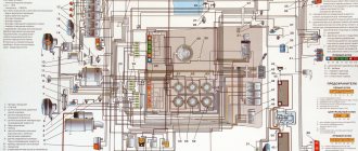
The wires must be connected according to the color diagram.
Panel for MTZ with large cabin
Since 1980, Belarus MTZ 80(82) tractors began to be equipped with a large observation cabin. In this assembly, they began to install another panel, indicated by catalog article 80-3805010-D1, with autonomous instrumentation (with instrument panel 80-385021-01), which was subsequently installed on tractor brands MTZ 100(102), 1221.
Instrument panel MTZ 80(82) with autonomous devices 80-3805010-D1
The shield is made of composite plastic, is installed on top of the common body of the control devices and is a single inclined plane with a hole for the steering wheel. Three blocks with fuses are mounted under the front front cover of the shield in a separate compartment.
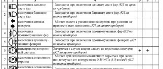
Panel warning lights
The upper part of the instrument panel is equipped with blocks of warning lamps (BKL 3803-03 and BKL 3803-01), which indicate the operating status of tractor systems or individual components.
Signaling lamps of the MTZ 82 control panel
- 1 and 14 buttons for checking the operation of indicator lamps. In good condition, all lamps should light up when the buttons are pressed.
- Lamp 2 indicates that the air filter is dirty. If there is unacceptable contamination, it lights up orange.
- 3- reserve lamp.
- 4 Lamp that controls the start of the diesel engine (When you turn the starter control toggle switch to the first position to start the engine, the lamp lights up in orange, which means that the starting system is working.) A flashing lamp with a frequency of 1.5 Hz means that the gearbox lever is not occupies the “Neutral” position or a malfunction is detected in the diesel start interlock switch circuit. If the lamp blinks at a frequency of 3 Hz, it indicates a malfunction of the generator winding circuit.
- 5 - alarm for monitoring the operation of the electric torch heater. With the heating system turned on, the lamp will glow orange. After 30 minutes, the lamp will begin to flash, indicating that the engine is ready to start.
- 6 red emergency pressure lamp in the HPS system, lights up when there is an unacceptable pressure drop.
- 7-reserve.
- 8 – blue indicator of high beam headlights.
- 9 – control lamp for differential lock operation.
- 10 – reserve.
- 11 green indicator of the tractor turn signal operation.
- 12 green trailer turn signal indicator.
- 13 red parking brake indicator
Autonomous panel devices
The sensors are located on the left side of the shield plane:
- Coolant temperature indicator EI 8008-03 with warning lamp for emergency temperature rise
- fuel level indicator in the tank EI 8007-2
- voltage indicator in the electrical network of the tractor EI 8006-2
- diesel oil pressure indicator EI 8009-9 with warning lamp for emergency pressure in the lubrication system
- air pressure indicator in the pneumatic system EI 8009-11
Oil pressure sensor EI 8009-9 Coolant temperature sensor EI8008-3 on MTZ 80 Fuel sensor EI 8007-2 Voltmeter EI 8006-2 Air pressure sensor EI 8009-11
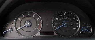
Tachometer
The AP70.3813 device is located on the right side of the panel with the AP70.3709-01 setting panel located below. The sensor display consists of a number of indicators:
Tachometer speedometer for MTZ tractor
- digital speed indicator 6 for vehicle movement from 0 to 50 km/h on one display 7 with an hour meter
- dial indicator 8 with scale 1 diesel crankshaft rotation speed from 0 to 3500 rpm.
- LED scale 4 indicating the rotation speed of a two-speed independent PTO 2.3 tractor
- digital counter 5 of the total operating time of the diesel engine from 0 to 9999 engine hours
MTZ 80 tractor tachometer
The tachometer speedometer programming parameters are set by the manufacturer in accordance with the make of the tractor, the rolling radius of the rear drive wheels and the brand of diesel engine. Resetting the tachometer speedometer is only necessary when changing the size of the rear wheels. If it is necessary to completely reprogram the sensor, the settings are carried out according to the instructions in accordance with the tabular data.
Row of toggle switches
The switches are located in the lower left part of the panel:
- emergency stop switch 245.3710,
- light switch with two positions (I - panel backlight is on, II - car road lights are additionally on) P147M-04.29,
- windshield washer switch P150M-14.10,
- switch for pre-start electric torch heater P150M-19.44.
Control panel design
In the lower right corner of the panel there is a switch 1202.3704-03 for the instrument panel and starter with a key socket. In addition, the kit includes a remote lever switch for turn signal lights, high-low beam and horn with a bracket for mounting on the steering column. The remaining switches are located on a separate top panel at the front of the cabin ceiling.
MTZ instrument cluster
Thanks to precise sensors, the operation of the system of modern automotive equipment is monitored.
In this article we will look at the design of the MTZ instrument cluster, as well as the optimal performance of lamps.
Most mechanisms include:
- Fuel volume indicator (1.1 reserve volume lamp);
- Pneumatic system pressure indicator (2.1 lamp turns on when an unsafe pressure level in the pneumatic system is reached);
- Voltage indicator (the MTZ instrument cluster also contains a 3.1 module - an additional battery charging lamp);
- Coolant temperature gauge (4.1 emergency system lamp);
- Engine oil pressure indicator (5.1 emergency lamp);
- Indicator of the optimal pressure in the tractor transmission oil.
The divisions are located on the fuel volume indicator scale. There is also a lamp here.
As a rule, the sensor lights up only when the amount of fuel decreases to 1/8 of the total volume.
Therefore, we advise you not to allow the fuel level in the tank to reach a minimum level. Follow the readings of the MTZ instrument cluster (the arrow will be located on the orange indicator).
In turn, the optimal pressure indicator in the pneumatic system has 2 modules:
- Worker (green);
- Emergency (red color).
The red warning lamp lights up when the pressure decreases to approximately 500 kPa.
The voltage sensor monitors the battery voltage if the diesel engine is turned off. In this case, the starter switch key is in position I.
The zones on the indicator scale will tell you about the state of the power system.
Do not forget that the MTZ 82 instrument cluster indicates a breakdown of the generator drive belt if the battery is not charged.
The engine coolant temperature sensor processes data from the engine block.
Has 3 zones:
- Informational;
- Emergency;
- Working.
The zones have the following colors: green (working), red (emergency), information (yellow).
The oil pressure sensor in the engine lubrication system processes information from the ECU. As in previous elements of the instrument cluster, MTZ 82 is equipped with 2 zones - emergency (red), working (green).
When the pressure drops to 100 kPa, the emergency lamp lights up.
However, if you start a cold MTZ engine, the pressure will reach 600 kPa.
If the emergency pressure lamp turns on while the engine is running, you must stop the engine immediately. After this, we advise you to inspect the systems and eliminate the malfunction.
You can buy the MTZ 82 instrument cluster on our website. The part is very durable and reliable. Rarely fails.
Replacing the shield on the tractor
The electrical system, an important part of which is the dashboard of this tractor, is one of the main elements of its design. At the same time, owners of such devices often have to deal with various malfunctions that make the correct operation of the MTZ impossible.
Most often, you encounter incorrect display of performance indicators when you turn on the ignition or activate certain functions, such as lighting, heating system, or pressing the brake pedal. Such a problem may indicate a serious breakdown hidden in the electrical circuit of the device.
With a high probability, it signals that there is no connection with the positive or negative wire. To resolve, it may be necessary to “ring” the entire wire to find the faulty section.
Often, incorrect operation of devices can be caused by damaged fuses, which will require their immediate replacement. Since repairing individual elements of the dashboard seems to be a complex procedure that will require highly qualified technicians, many prefer to turn to specialists.
Be sure to read: Technical characteristics of the A-41 engine
If the tractor owner wants to restore the element’s functionality on his own, a promising option may be to completely replace the panel and connect it to the MTZ electrical circuit. To do this, you will need to adhere to the following algorithm of actions:
- Disconnect the battery from the tractor power supply.
- Remove the fastening elements by which the instrument panel is installed in the cabin.
- Remove the broken device, replace it with a new one, which will need to be connected, guided by the MTZ 80 electrical diagram.
- Install fasteners.
This procedure is quite simple, but is not suitable for those owners who do not have the necessary knowledge about the electrical system implemented in this series of tractors.
Source
Description of the types of instrument panels MTZ 82(80)
Over the course of more than forty years of production, the Belarus tractor has undergone a number of changes in the cabin interior due to the modernization of the machine and the improvement of the control system for the operation of mechanisms and components, as well as due to the improvement of the ergonomic qualities of the driver’s workplace. Speaking about equipping the MTZ 80(82) with control and measuring sensors, it should be noted that the tractor, depending on the year of manufacture, is equipped with three versions of instrument panels, which are an integral part of the control system.
Instrument panel MTZ 80.1
Old style panel
This instrument panel (with catalog article 70L-3801010 for a tractor with a starter and 70-3801010 with a starter) has been installed since 1974 on the MTZ 80(82) with a small cabin. The unit is a sheet metal housing with an opening for the steering axis.
Old instrument panel of the MTZ 80 tractor
In the front part, on a small inclined plane, separate mechanical type indicator sensors are located from left to right:
- coolant temperature UK133-V
- ammeter AP110
- air pressure in the MD 226 pneumatic system
- oil pressure in the MD 219 engine
- tachospeedometer TX-135
- Additionally, a fuel level sensor in the tank UB 126 is attached to a separate bracket on the right side.
Tachometer speedometer TX 135 Air pressure sensor MD 226 Oil pressure sensor MD 219 Coolant temperature sensor UK 133V Ammeter AP 110 Fuel level sensor UB 126
On a large horizontal area there is a row of colored warning lamps, covered with a shield in the position from left to right:
Behind the lamps, closer to the driver, there is a row of switches:
- toggle switch for high and low beam
- turn signal toggle switch
- horn button
On the right side of the steering wheel seats are located:
- element PD 50V(20) for monitoring the degree of heating of the coil of an electric torch heater
- starter control switch (23).
In the rear end part of the shield, under the cover, there is a fuse block for the tractor electrical system and a handle for the headlight mode switch.
Today, analogues of this panel are produced by various manufacturers, which may differ in the additional equipment of an emergency stop button and an electric cigarette lighter wick.
How to operate MTZ 82
The location of the tractor controls is shown in Fig.
3 a, b. 1 — diesel engine stop and emergency stop handle. When you pull the handle toward you, the fuel supply to the cylinders stops and the diesel engine stalls. When released, the handle returns to its original position under the influence of a spring.
2 — control handle for the cabin heater valve (if installed).
3 — differential lock control handle (for tractors with power steering housing); has three provisions:
- I "lock off"
- II "automatic blocking",
- III “forced blocking”.
4 — handwheel for controlling the water radiator shutter. When the handwheel rotates clockwise, the curtain rises; when rotated counterclockwise, it lowers. When the curtain is lowered, the temperature of the diesel engine decreases.
5 — rear axle differential lock pedal. When you press the pedal all the way, the lock is turned on, when you remove your foot from the pedal, it turns off.
6 - switch for starting aids (EFS).
7 — windshield washer switch.
8 - light switch. It has two positions: I — instrument lighting and side lights are on; II - in addition to position I, road headlights are turned on.
9 — alarm switch.
17—switch for direction indicators, low and high beams, sound signal.
19 — radio receiver (optional).
20 — cover of the steering wheel height adjustment mechanism. To change the height, remove the cover, unscrew the wing nut 3-5 turns and set the required steering wheel height.
21 — front window wiper switch.
22 — cabin heater fan switch.
23 - switch for rear working lights.
24 - front working headlight switch.
24a—switch for the “Road Train” sign.
25—cabin light with switch.
26 — air distributor of the cabin ventilation and heating system.
Important! Before you start working on the tractor, study the purpose of the controls, instruments and their functions.
27, 28, 29 — hydraulic system distributor control levers: 27 — left side terminals; 28 — right side terminals; 29 - rear terminals. If the tractor does not have a power regulator, then lever 29 controls the cylinder of the hitch, and lever 27 controls the left side and rear outputs duplicated with it. The connection diagram for the hydraulic system terminals is shown on the instruction plate in the tractor cabin (see Fig. 4.1). Each lever has 4 positions: “floating”, “forced lowering”, “neutral”, “raising”. In the “forced lowering” position with the engine running, the lever should be held by hand.
30— tachometer speedometer control panel (see Fig. 9.2).
31 - starter and instrument switch. Has three positions (from neutral):
- I - power supply of devices;
- II - turning on the starter;
- position counterclockwise from neutral - the radio is on.
32 — lever for turning on the reduction gear. It has two positions: front - “Gearbox on” (slow movement of the tractor) and rear - “Gearbox off” (fast movement of the tractor).
In a tractor with a synchronized reduction gearbox, the control lever 32 has two positions: rear - “Gearbox on” (slow movement of the tractor) and front - “Gearbox off” (accelerated movement of the tractor).
In a tractor with a synchronized reverse gearbox, control lever 32a (Fig. 4.1.1) (unlike lever 32 is bent to the left along the tractor) has two positions: rear - “Reverse on” and front - “Reverse off” (forward travel) .
33 — connecting bar of the brake pedals for simultaneous braking with the right and left brakes.
34 — fuel control pedal.
35, 36 — brake pedals. When you press the pedals with your foot, the tractor slows down; at the same time, the brake valve of the pneumatic drive of the trailer brakes is activated from pedal 35. 37 — handle for fixing the tilt of the steering column.
38— clutch control pedal.
39 — gear shift lever. When moving the lever forward in the extreme left position, the 2nd (increased) gear range is switched on, and back - the 1st (lower) gear range. Gear shifting is carried out in accordance with the diagram (Fig. 4.2.).
40 — control lever for the attachment fixing mechanism. The extreme left position of the lever is “the hitch is fixed”, the extreme right is “the fixation is removed”. You must first raise the hitch to the top position.
41 — control lever for the transfer case of the FDA drive. The middle position of the lever is “FDR is switched on automatically”, lower (pull) – “FDR is switched off”, upper (pull) – “FDR is forcibly switched on”.
42 — parking brake control lever.
43 — lock of the power regulator control handle.
44 — fuel supply control handle. The extreme forward position is the maximum fuel supply, the rearmost position is the minimum supply corresponding to the minimum idle speed.
45 — power regulator control handle. The rearmost position of the handle is “raising the implement” (while lifting, hold the handle with your hand); after releasing the handle, it moves forward and is fixed in the “transport neutral” position. The intermediate position forward from the “transport neutral” position is the “regulatory zone”. The extreme forward position of the handle is “forced lowering” (hold the handle with your hand). After releasing the handle, it returns back and is fixed at the leading edge of the control zone.
46 — rear PTO control lever. It has two positions: front - “PTO off”, rear - “PTO on”.
47 - battery ground switch.
48— seat back tilt lock.
49 — seat belt bolt
Diagram of tractor speeds in km/h at a rotation speed of 1600. 2200 rpm of the diesel crankshaft (rear tires 15.5R38) (Belarus 80.1/80.2/82.1/82.2)
50 — lever for fixing the seat in the longitudinal plane. By moving the lever all the way up, the seat can be moved forward or backward.
51 — handle for adjusting the seat according to the operator’s weight. When the handle is rotated clockwise, it is adjusted to a larger mass, and counterclockwise, to a smaller one.
Seat height adjustment is carried out: a) to increase the height of the seat - by successively manually moving the seat up; b) to reduce the height - with a sharp lift, the seat moves up to the stop, followed by lowering (push down) to the lowest position, after which it rises up to the desired lower height.
52 - power (position) regulator switch. It has three positions: right - “positional regulation”, left – “force regulation”; middle - “off”.
53 - handwheel for controlling the speed of correction by the power regulator. When turning the handwheel clockwise, the correction speed decreases, and counterclockwise, it increases.
54 — hydraulic hook grip control handle. The lower position of the handle is “grips under load”, the upper position is “grips free from load”.
55 — handle for switching the rear PTO from independent to synchronous drive. When the handle is moved to the extreme left position (along the tractor's direction), the synchronous drive is activated; when the handle is moved to the extreme right, the independent drive is activated; the middle position is neutral.
56 - handle (Fig. 5) for turning on the compressor. It has two positions: left (arrow on the handle faces forward) - “compressor off”, right (arrow on the handle faces back) - “compressor on”. Turn on the compressor when the diesel engine is not running or at minimum idle speed.
57 — lever (Fig. 6) for turning on the hydraulic system pump. It has two positions: upper – “pump on”, lower – “pump off”. To move the lever, it must be released from fixation by pulling handle B.
58 — driver (Fig. 7) for switching the rotation speed of the rear independent PTO. When the driver is turned to position I, the 1st stage (540 rpm) is switched on; when turned to position II, the 2nd stage (1000 rpm) is activated. Before switching, unscrew bolt “A” one turn and after switching, tighten it until it stops.
Panel for MTZ with large cabin
Since 1980, Belarus MTZ 80(82) tractors began to be equipped with a large observation cabin. In this assembly, they began to install another panel, indicated by catalog article 80-3805010-D1, with autonomous instrumentation (with instrument panel 80-385021-01), which was subsequently installed on tractor brands MTZ 100(102), 1221.
Instrument panel MTZ 80(82) with autonomous devices 80-3805010-D1
The shield is made of composite plastic, is installed on top of the common body of the control devices and is a single inclined plane with a hole for the steering wheel. Three blocks with fuses are mounted under the front front cover of the shield in a separate compartment.
Panel warning lights
The upper part of the instrument panel is equipped with blocks of warning lamps (BKL 3803-03 and BKL 3803-01), which indicate the operating status of tractor systems or individual components.
Signaling lamps of the MTZ 82 control panel
- 1 and 14 buttons for checking the operation of indicator lamps. In good condition, all lamps should light up when the buttons are pressed.
- Lamp 2 indicates that the air filter is dirty. If there is unacceptable contamination, it lights up orange.
- 3- reserve lamp.
- 4 Lamp that controls the start of the diesel engine (When you turn the starter control toggle switch to the first position to start the engine, the lamp lights up in orange, which means that the starting system is working.) A flashing lamp with a frequency of 1.5 Hz means that the gearbox lever is not occupies the “Neutral” position or a malfunction is detected in the diesel start interlock switch circuit. If the lamp blinks at a frequency of 3 Hz, it indicates a malfunction of the generator winding circuit.
- 5 - alarm for monitoring the operation of the electric torch heater. With the heating system turned on, the lamp will glow orange. After 30 minutes, the lamp will begin to flash, indicating that the engine is ready to start.
- 6 red emergency pressure lamp in the HPS system, lights up when there is an unacceptable pressure drop.
- 7-reserve.
- 8 – blue indicator of high beam headlights.
- 9 – control lamp for differential lock operation.
- 10 – reserve.
- 11 green indicator of the tractor turn signal operation.
- 12 green trailer turn signal indicator.
- 13 red parking brake indicator
Autonomous panel devices
The sensors are located on the left side of the shield plane:
- Coolant temperature indicator EI 8008-03 with warning lamp for emergency temperature rise
- fuel level indicator in the tank EI 8007-2
- voltage indicator in the electrical network of the tractor EI 8006-2
- diesel oil pressure indicator EI 8009-9 with warning lamp for emergency pressure in the lubrication system
- air pressure indicator in the pneumatic system EI 8009-11
Oil pressure sensor EI 8009-9 Coolant temperature sensor EI8008-3 on MTZ 80 Fuel sensor EI 8007-2 Voltmeter EI 8006-2 Air pressure sensor EI 8009-11
Tachometer
The AP70.3813 device is located on the right side of the panel with the AP70.3709-01 setting panel located below. The sensor display consists of a number of indicators:
Tachometer speedometer for MTZ tractor
- digital speed indicator 6 for vehicle movement from 0 to 50 km/h on one display 7 with an hour meter
- dial indicator 8 with scale 1 diesel crankshaft rotation speed from 0 to 3500 rpm.
- LED scale 4 indicating the rotation speed of a two-speed independent PTO 2.3 tractor
- digital counter 5 of the total operating time of the diesel engine from 0 to 9999 engine hours
Instrument cluster of the Belarus MTZ-82.1 tractor
_____________________________________________________________________________
_____________________________________________________________________________
____________________________________________________________________________________________
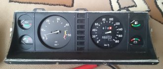
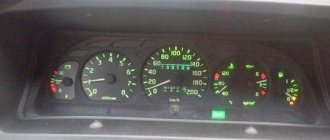
The instrument cluster includes five gauges with five warning lamps, as shown in the figure. Fig.7. Instrument cluster of tractors Belarus MTZ-82.1, 80.1, 82.2 1 – warning lamp for reserve fuel level in the tank; 2 – air pressure indicator in the pneumatic system; 3 – warning lamp for emergency air pressure in the pneumatic system; 4 – fuel level indicator in the tank; 5 – voltage indicator; 6 – unused signal lamp; 7 – warning lamp for emergency engine coolant temperature; 8 – engine coolant temperature indicator; 9 – warning lamp for emergency oil pressure in the engine lubrication system; 10 – oil pressure indicator in the engine lubrication system. The scale of the air pressure indicator in pneumatic system 2 has three zones: - working - from 500 to 800 kPa (green); — emergency (two) — from 0 to 500 kPa and from 800 to 1000 kPa (red). The indicator scale has a built-in warning lamp 3 (red), which lights up when the pressure in the pneumatic system drops below 500 kPa. Voltage indicator 5 shows the battery voltage when the Belarus MTZ-82-1, 80-1 engine is not running, when the starter and instrument switch key is in position “I”. When the engine is running, the voltage indicator shows the voltage in the on-board network, which is set by the generator. The scale of the fuel level indicator in tank 4 has divisions “0–1/4–1/2–3/4–1” (option 1), or “0–0.5–1” (option 2). The indicator scale has a built-in warning lamp 1 (orange), which lights up when the fuel level in the tank drops to 1/8 of the total tank volume. The scale of the engine coolant temperature indicator has three zones: - working - from 80 to 105 ° C (green); - informational - from 40 to 80 °C (yellow); - emergency - from 105 to 120 °C (red). An emergency temperature warning lamp (red) 7 is built into the indicator scale, which lights up when the coolant temperature is 105 °C and above. The scale of the oil pressure indicator in the engine lubrication system 10 has three zones: - working - from 100 to 500 kPa (green); - emergency (two) - 0 to 100 kPa and from 500 to 600 kPa (red). The indicator scale has a built-in warning lamp for emergency oil pressure drop 9 (red), which lights up when the pressure drops below 100 kPa. Blocks of warning lamps Two blocks of warning lamps are installed in the instrument panel of tractors Belarus MTZ-82.1, 80.1. Each BCL includes six indicator lamps and one button for checking the functionality of the indicator lamps. Fig.8. Warning lamp blocks 1, 14 – button for checking the functionality of the warning lamps; 2 – indicator lamp for maximum clogging of the air cleaner filter (orange); 3, 4, 7, 9, 10 – unused control lamps, 5 – control lamp indicating the operation of glow plugs (orange); 6 — warning lamp for emergency drop in oil pressure in the HPS system (red); 8 – control lamp indicator for turning on the high beam of road headlights; 11 – control lamp-indicator of turning on the tractor direction indicators; 12 – control lamp - indicator for turning on the direction indicators of the tractor trailer; 13 – indicator lamp for turning on the parking brake. The principle of operation of the LCL control lamps is as follows: - when you press button 1, all lamps on the left LCL should light up. When you press button 14, all the lamps on the right BCL should light up. If one of the six indicator lamps used (2, 5, 6, 8, 11, 12 or 13) does not light up, it is necessary to install a working lamp or replace the indicator lamp unit (if LEDs are installed); — the indicator lamp for maximum clogging of the air cleaner filter 2 lights up when the maximum permissible level of filter clogging is exceeded and it needs to be cleaned or replaced; — the glow plug operation indicator lamp displays the operation of the glow plugs; — the control lamp-indicator for turning on the high beam of road headlights 8 lights up when the high beam of road headlights is turned on; — indicators 11 and 12 for turning on the tractor and tractor trailer turn indicators operate in a flashing mode when the steering column multifunction switch 1 turns on the right or left turn signal, or when the hazard warning switch 2 is turned on; — the parking brake activation warning lamp 13 operates in a flashing mode with a frequency of 1 Hz when the parking brake activation sensor is triggered; — warning lamp 6 for an emergency drop in oil pressure in the HPS hydraulic system lights up when the oil pressure in the HPS hydraulic system drops below 0.08 MPa (lamp 6 is allowed to light up periodically at minimum engine speed - when engine speed increases, lamp 6 should go out). When installing power steering instead of power steering, indicator lamp 6 is not used. Tachospeedometer AR70.3813 Fig.9. Tachometer speedometer AR70.3813 1 – engine speed scale, min-1; 2 – high voltage indicator in the tractor on-board network (red); 3 – rear PTO speed indicator in 1000 min-1 mode (light indicator); 4 – rear PTO speed indicator in 540 min-1 mode (light indicator); 5 – rear PTO speed indication display; 6 – display (LCD) indicating the total engine operating time and tractor speed; 7 – arrow indicator of engine crankshaft speed. Operating procedure of the tachometer speedometer AR70.3813 On a stopped Belarus MTZ-82-1, 80-1, 82-2 tractor, after setting the starter switch and instruments to position “I”, an indication of the engine operating time in hours (h) appears on display 6. After starting the engine, the pointer 7 moves along the circular scale 1 to indicate the engine crankshaft speed.
At the same time, an indication of the estimated rotation speed of the rear PTO (min-1) appears on display 5 - on scale 3 for the rear PTO in the 1000 min-1 mode and on scale 4 for the rear PTO in the 540 min-1 mode. The rotation speed of the rear PTO is calculated based on the signal from the phase winding of the generator. When the tractor moves, an indication of the estimated tractor speed (km/h) appears on display 6, while the engine operating time indication disappears. Speed readings are carried out based on a signal from a sensor installed on the final drive gear of a wheel rotating at a lower frequency. The calculated speed is slightly higher than the actual speed, because Tractor slipping is not taken into account. If, while the tractor is moving, the numbers “02-07” appear on display 6 instead of speed readings, and after 12±1 seconds the number “0” appears on the right side of display 6, this means that there is no signal from the right speed sensor. The problem needs to be corrected. If, while driving the Belarus MTZ-82.1, 80.1 tractor, the numbers “02-07” appear on display 6 instead of speed readings, and after 12±1 seconds the number “0” on the left side of display 6, this means that there is no signal from left speed sensor. The problem needs to be corrected. There are no speed indications on display 6. To restore speed readings, it is necessary to eliminate the above faults. Indicator 2 for high voltage on-board power supply of the tractor lights up when the on-board power supply voltage is above 18V and goes out when the supply voltage drops below 16 V. While indicator 2 is on, the tachometer speedometer does not function. If the voltage in the tractor's electrical system increases above 18V, the tachometer speedometer backlight lamps may fail if they were turned on. In this case, it is necessary to replace the tachometer speedometer backlight lamps. Combined indicator KD 8083 Fig. 10. Combined indicator KD 8083 1 – high voltage indicator in the tractor on-board network (red); 2 – engine speed indicator (arrow indicator); 3 – rear PTO speed indicator in 1000 min-1 mode (light indicator); 4 – rear PTO speed indicator in 540 min-1 mode (light indicator); 5 – rear PTO speed indication display; 6 – LEDs illuminated in the mode of displaying the driving speed “km/h” and the total operating time of the engine “h” (opposite the corresponding LED); 7 – LEDs illuminated in the mode of programming the coefficients “K”, “R”, “Z” and LED “T” illuminated in the mode of indicating the specified total engine operating time (opposite the corresponding LED); 8 – display (LCD) indicating the total engine operating time and tractor speed. Operating procedure of the combined indicator KD 8083 On a stopped Belarus MTZ-82-1, 80-1 tractor, after setting the starter switch and instruments to the “I” position, an indication of engine operating time in hours (h) appears on display 8 and LED 6, located next to symbol "h". After the engine starts, the engine speed indicator 2 displays the engine speed. At the same time, an indication of the estimated rotation speed of the rear PTO (min-1) appears on display 5 - on scale 3 for the rear PTO in the 1000 min-1 mode and on scale 4 for the rear PTO in the 540 min-1 mode. The rotation speed of the rear PTO is calculated based on the signal from the phase winding of the generator. When the tractor moves, an indication of the estimated tractor speed (km/h) appears on display 8 and LED 6, located next to the “km/h” symbol, lights up. In this case, the engine operating time indication disappears. Speed readings are carried out based on a signal from a sensor installed on the final drive gear of a wheel rotating at a lower frequency. The calculated speed is slightly higher than the actual speed, because Tractor slipping is not taken into account. If 12±1 seconds after the start of movement, or during movement, the “rectangle” symbol is displayed on the right side of display 8, this means that there is no signal from the right speed sensor. If 12±1 seconds after the start of movement, or during movement, a symbol is displayed on the left side of display 8, this means that there is no signal from the left speed sensor. The problem needs to be corrected. There are no speed indications on display 8. To restore speed readings, it is necessary to eliminate the above faults. Indicator 1 of high voltage in the tractor's on-board network lights up when the voltage rises above 18V and goes out when the supply voltage drops below 16V. While indicator 1 is on, the IR does not function. If the voltage in the tractor's electrical system increases above 18V, the IR backlight lamps may fail if they were turned on. In this case, it is necessary to replace the IR illumination lamps.
_____________________________________________________________________________
__________________________________________________________________________
Service and adjustments MTZ-82
- Controls and instruments
- Working with agricultural machinery
- Maintenance of diesel engine D-243
- Clutch adjustments
- Steering
- Tractor brakes Belarus
- PTO power take-off shaft
- Front axle
- Front drive axle repair
- Hydraulic system and rear linkage
- Electrical equipment
- Maintenance
__________________________________________________________________________
Operation and service MTZ-82.1, 80.1, 80.2, 82.2
- Controls and instruments
- Gearbox and PTO control
- Rear linkage control
- Cabin elements
- Electrical components
- Clutch
- Transmission
- Gearbox and creeper control
- Reverse gearbox
- Rear axle of Belarus tractor
- Rear axle differential lock
- Rear power take-off shaft
- Tractor brakes Belarus
- Pneumatic system
- FDA with bevel wheel reducers
- FDA with planetary helical wheel reducers
- FDA drive
- Chassis system
- Hydrostatic steering
- Power steering
- Hydraulic linkage system
- Rear linkage adjustments
- Cabin Belarus
- Maintenance
- Engine Maintenance
- Transmission Maintenance
- Front drive maintenance service
- Hydraulic and steering maintenance
- Front Axle Maintenance
- Maintenance of the pneumatic system and brakes
Repair of MTZ-80
- Cylinder head repair
- Repair of piston group D-240
- Repair of fuel equipment
- Starting motor repair
- Steering repair
- Front axle repair
- Clutch and reduction gear repair
- Transmission repair
- Rear axle repair
- PTO repair
- Rear linkage hydraulic system repair
- Electrical equipment repair
Maintenance and operation of MTZ-1221
- Controls and instruments
- Transmission
- Clutch
- D-260 engine maintenance
- Rear axle
- Service brakes
- Pneumatic equipment
- PTO
- Front drive axle
- Mounted hydraulic system
- Electronic rear linkage control
- Rear linkage
- Steering
Maintenance and operation of MTZ-320
- Controls and instruments
- Diesel engine
- Clutch and gearbox
- Rear axle
- Brakes
- Rear power take-off shaft
- Front drive axle
- Steering
- Hitch and hitch
- Hydraulic system
- Electrical equipment
- Aggregation
Operation and service of tractors
- Block crankcase and crank mechanism
- Gas distribution mechanism
- Diesel engine power supply system
- Tractor engine control system
- Tractor engine cooling system
- Diesel starting system
- Tractor power transmissions
- Tractor transmission T-150, T-150K
- Drive axles of wheeled and tracked tractors
- Tractor chassis and control
- Chassis and steering of wheeled tractors