Characteristics of fuel injection pump
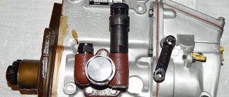
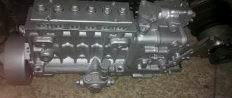
The MTZ fuel pump belongs to the category of four-plunger units and is designed to ensure the necessary fuel circulation. In the design of the tractor, it is located in one block with a pumping analogue and a centrifugal regulator. The block is located on the left side of the D-240 engine, secured with bolts to the distribution cover.
Before you figure out how to add fuel to the MTZ injection pump, you need to become more familiar with its characteristics and features. Correct operation of the unit is ensured by the action of the crankshaft, which drives it through a gear mechanism.
Among the most significant characteristics of this important element it is advisable to include:
- manufacturer - Noginsk;
- spare parts catalog number - 4UTNI-1111005-20;
- scope of application - power units of the D series (from 240 to 248.1 modification) for various MTZ models;
- drive type - splined bushing.
The MTZ 82 fuel equipment is not a completely unique development, since it has foreign analogues. An example is the Czech-made PP4M9P1g-4201, which is almost identical in its technical design and characteristics.
Fuel equipment MTZ-80, MTZ-82, engine D-243
No vehicle with a diesel engine can do without fuel equipment.
The fuel pump d-243 is suitable for MTZ equipment, PAZ buses, ZIL 4331, LAZ 695 trucks. The fuel system of a diesel engine consists of components that depend on each other and are connected by fuel lines. The fuel pump of the D-243 engine has a double-lever control system and a 3-pin drive, which eliminates errors in its operation due to the absence of backlash. The injection pump 4utni-1111007-420, installed on the D-243 at the outlet to the injectors, has a higher fuel pressure relative to the injection pump D-240, which contributes to better atomization of the fuel by the sprayer into the combustion chamber of the cylinder. Thus, the combustion of the fuel mixture approaches 100%, which leads to engine efficiency.
The MTZ d-243 fuel pump is installed for engines running on diesel fuel without turbocharging and having a volume of each cylinder not exceeding 1.5 liters.
Device
When planning to repair the MTZ fuel injection pump, you should familiarize yourself in more detail with the design of such an element. It is distinguished by a minimum number of elements and high reliability, which makes it possible to significantly simplify the procedure for adjusting the pump, as well as troubleshooting. The main components of this unit are:
- plunger pairs;
- frame;
- pressure type valve;
- pushers;
- camshaft;
- plunger drive mechanism.
The pump head and housing are a single element made of high-strength aluminum alloy. The design of the unit provides that a special plate is placed on the front part of the housing, which is used to mount the product directly on the engine. When figuring out how to remove the injection pump from the MTZ 82, it should be noted that to do this it is enough to remove the mounting bolts.
The back of the plate is equipped with a special flange, which is used to install the regulator. The principle of operation of the product is extremely simple, it involves the following algorithm of actions:
- The cam shaft begins to rotate, lifting the pusher with the help of a roller.
- The pusher moves down together with the plunger.
- Fuel fills the space in the sleeve vacated by the descent of the plunger.
- When the element returns to its original state, pressure is created, due to which, with the help of a valve, a portion of fuel flows through the nozzles.
This cycle is repeated at certain intervals, which allows you to maintain the fuel level necessary for proper engine operation.
Design of the injection pump of the MTZ 80 tractor
The tractor pump for MTZ 80 is called UTN-5. It is made of reliable aluminum alloy. And they are produced in different mounting variations; there are left and right versions. This depends on the design and properties of the fastener. Along the entire length of the body it is divided into two cavities. This happens thanks to the partition. At the bottom there is a shaft with a pump drive, and at the top there are the component sections of this pump.
We will consider the detailed design of the injection pump of the D-240 engine further. A fuel pump with a control mechanism has the following elements: pressure fitting, discharge valve, valve seat, plunger and corresponding bushing, rotary bushing, ring with teeth, rack rod, regulator cover, corrector body, corrector rod, regulator body, heel, weight axles , heel and lever, coupling, adjuster weights, weight hub, shock absorber block, bearing cup, oil deflector, shaft with cam, plug, pump mounting flange for inflating, mounting plate, splined bushing, installation flange, roller tappet, lower spring plate, rack with gear, fuel outlet channels, bypass valve body, diesel supply hole, ball valve, fuel channels, shut-off hole, pin, plunger bushing inlet hole, manhole cover. Like any pump, the injection pump in its design has washers, clamps, main and auxiliary levers, bolts for various purposes, ball bearings, springs, plugs, nuts, gaskets, fuel transfer tubes, various screws for tightening and adjustment. There is no pump in nature without a housing and an oil hole, and there are no pumps without an eccentric for pumping fuel.
Diagram of a fuel pump with regulator
The fuel system of a diesel engine includes: an air cleaner, a muffler, an air filter, an electric torch heater with a fuel tank, an intake manifold, various pipes - drainage and high pressure, a throat for filling fuel, fuel tanks, a drain valve, fine and coarse filters for diesel fuel, fuel pump regulator, booster pump, fuel pump, injectors, exhaust manifold, filter devices for various purposes.
At the highest point of UTN-5 there are longitudinal channels connecting it to a fine filter and to the pumping system of the pump, which has a built-in bypass valve.
Description of the method of action of UTN - 5
The booster pump is attached to the main pump housing. A fuel line is connected to the fittings, through which fuel is supplied to the injectors under high pressure. The pump is driven by the crankshaft gear. If the pump has already been repaired, then after the next assembly and disassembly it is necessary to carefully check the angle of the gear connections. Otherwise, if tilted incorrectly, there will be interruptions in performance. The degree of inclination must be strictly 22°30″. It is better to check it by contacting an experienced mechanic.
Checking and adjusting the pump
Before starting, you need to make sure that the locking cone fits tightly and that the pressure of the pump section is normal. Rotate the crankshaft and move the regulator until the arrow on the pressure gauge shows 15 MPa. The engine is then turned off and the fuel supply is stopped using the control lever. If the pressure on the pressure gauge drops within ten seconds, the valve is good.
To adjust the exact angle of the moment of fuel entry, you need to turn the adjusting bolt in different directions. One turn reduces or increases crankshaft speed by approximately 40 revolutions. Unscrewing the bolt reduces the power of the pump; tightening it increases it.
Technical Tips
Logically, it can be calculated that by increasing the amount of fuel supplied to the combustion chamber, the torque also increases. And this increases engine power and speed.
Changing the engine oil in the UTN-5 device is necessary only after dismantling and repair work. This should not be done during normal operation. Only 150-200 milliliters of engine oil is required; filling is carried out through the injection pump crankcase.
Adjusting the fuel pump
One of the most important measures for servicing the fuel pump of the MTZ tractor is its adjustment. If it is performed correctly, the owner of the equipment will be able to avoid damage to the pump and other structural elements. Adjustment manipulations are carried out using a special stand, as well as the necessary tools:
- instruments that allow you to measure shaft rotation speed;
- disk for determining fuel supply;
- measuring containers for controlling fuel volumes;
- drive and variator, which are capable of smoothly changing rotation speed.
Speed indicators are adjusted using a bolt located in the product body, which is responsible for the degree of tension of the control spring. Screwing in the bolt leads to an increase in performance, and unscrewing it counterclockwise, on the contrary, will reduce the speed. The fuel supply is adjusted using a special sleeve, which works on a similar principle. For uniform feeding, you should use the nominal edge, which is also located on the body.
Trouble-shooting
There are several of the most common malfunctions that owners of MTZ tractors most often encounter. Since the price of the fuel pump is low, the technician can completely replace it if desired, but it will be much more economical to fix the breakdowns on his own.
The most common breakdown is wear of a pair of plungers , which is due to the low quality of the fuel and the abundance of impurities in it. For repairs, you will need to restore or replace damaged elements. To avoid damage, the fuel filter should be cleaned and replaced regularly.
Water hammer often leads to breakdowns due to the appearance of water in the system. If a problem occurs, you will need to thoroughly clean the element from any remaining moisture, and then restore its tightness.
Fuel injection pump of engine D 240 (fuel pump UTN-5) - design and adjustment
The four-plunger fuel pump (fuel pump) of the D 240 engine is installed in one unit with a booster pump and a centrifugal regulator on the left side of the engine (in the direction of travel of the tractor) and is bolted to the distribution cover. The fuel pump is driven by the crankshaft through timing gears (plunger stroke - 8 mm, plunger diameter - 8.5 mm).
UTN 5 device
The injection pump consists of the following main components: plunger pairs, housings, discharge valve, pushers, cam shaft, plunger drive mechanism. The fuel pump head and its housing are one piece and made of aluminum alloy.
A cast iron plate is attached to the front of the housing for mounting the pump on the engine, and at the rear there is a flange for mounting the regulator. All four sections of the pump are a miniature fuel pump, whose operating principle is as follows. As the cam shaft rotates, the cam protrusion runs up against the roller at a certain period of time and lifts the tappet. After the cam protrusion comes out from under the roller, the springs lower the pusher. Simultaneously with the pusher, the plunger rises and falls, thus producing a reciprocating movement in the cavity of the sleeve. As the plunger moves downward, fuel fills the space it vacated in the sleeve. During its upward movement, the plunger compresses the fuel and the pressure created opens the discharge valve, providing a path for the fuel to reach the injector. The cycle of suction and discharge is then repeated.
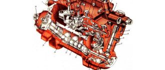
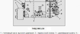
Diagram of the fuel pump UTN 5 of the D-240 diesel engine: 1 - housing; 2 - discharge valve; 3 - plunger pair; 4 - plunger; 5 — pusher bolt; 6 - cam shaft; 7 — splined bushing; 8 - mounting flange; 9 — booster pump; 10 — manual pump; 11 — air release plug; 12 - bypass valve; 13 — earring; 14 — regulator spring; 15 — corrector; 16 — breather; 17 — nominal bolt; 18 — regulator body; 19 — drain plug; 20 — control hole plug; 21 - plate; 22 — drain plug; 23 — bolt of maximum rotation speed; 24 — control lever; 25 — gear rack; 26 — ring gear; 27 - tightening screw.
The plunger rotation mechanism, which serves to change the fuel supply, consists of a rack and gear rims. The plunger bushings have rotary sleeves equipped with toothed rims. With its protrusions, the plunger fits into two longitudinal grooves of the rotary sleeve. A plunger spring is placed on the sleeve. Through the lower plate it rests against the pusher bolt, and through the upper plate it rests against the pump housing. The toothed rims of the sleeve are in constant engagement with the teeth of the rack, which moves in two bronze bushings. Using a rod, the rack is connected to the regulator levers and moves under their influence, turning the gear ring simultaneously with the plunger sleeve and thus changing the fuel supply.
Tangential profile cams are placed on the cam shaft symmetrically to each other. Between the second and third cams there is an eccentric that drives the fuel boost pump.
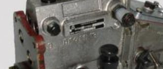
At the top of the rear part of the fuel pump housing of the MTZ 82 tractor there is a bypass valve through which excess fuel supplied by the fuel priming pump is returned to its suction chamber. Thus, the pressure in the channels of the D-240 diesel injection pump head is maintained in the range of 0.07-0.12 MPa (0.7-1.2 kgf/cm²). The pushers slide into holes in the horizontal partition of the fuel pump block. There is a hatch on the side wall of the housing, through which it regulates the uniformity of fuel supply across sections and, in fact, the fuel supply itself. A threaded hole is used to control the oil level in the pump housing.
To communicate the internal cavity of the fuel pump housing with the atmosphere, a breather is used, equipped with an air purification filter made of elastic foam.
Plunger pair
The plunger pair consists of a bushing and a plunger, which are the main working parts of the fuel pump. Thanks to it, the required amount of fuel is supplied to the engine cylinders under high pressure. The plunger and bushing are made of alloy steel, after which they are heat treated and form a precision pair. This design was implemented because during operation high pressure is generated in the pump, as a result of which tightness and vapor density are required to block the flow of fuel from the space above the plunger. The plunger pair cannot be disassembled and if one of the parts fails, the entire pair is replaced.
The upper part of the plunger pair bushing has a significant thickening, since in this place it is exposed to serious pressure. The upper thickened part of the bushing has an end in the form of a step to allow it to fit into the socket of the pump housing. There are two windows in the upper part of the sleeve: bypass and suction. Fuel is cut off and bypassed through the bypass window, and fuel is supplied to the space above the plunger through the suction port. These holes are connected in the upper part of the injection pump with longitudinal channels. The bushing is secured against rotation by a pin that fits into the milled groove of the bushing. The falling out of the pins is blocked by the hatch cover. The bushing is located on top of the pump housing, and the discharge valve is pressed to its upper end. To ensure the required tightness, the contacting ends of the injection valve seat and bushings have a well-ground surface.
Diagram of a plunger pair: 1 - fitting; 2 — pressure valve spring stop; 3 — discharge valve spring; 4 — discharge valve seat; 5 - discharge valve; 6 - seal; 7 - bushing; 8 - plunger; 9 - rack; 10 — ring gear; 11 — rotary sleeve; 12 — upper plate of the plunger spring; 13 — plunger spring; 14 — lower plate of the plunger spring; 15 — coupling screw; 16 and 17 - suction and bypass windows.
The plunger looks like a cylindrical rod, on the surface of which there is a pair of symmetrically placed spiral grooves, one of which is carefully processed and is designed to change the volume of fuel injected into the cylinder of the D-240 engine. When the edge of the bypass window of the bushing coincides with the edge of the groove, the pressure in the space above the plunger decreases sharply, and therefore the fuel supply to the injector stops. Another groove equalizes the specific fuel pressure acting on the side surface of the plunger during pump operation. On the plunger, below the cut-off edge, there is an annular groove where leaked fuel is retained, which is then used to lubricate the plunger pair. At the bottom of the plunger there are two protrusions to control its rotation and a head on which the spring plate rests.
Discharge valve
The discharge valve is used to disconnect the space above the plunger from the high pressure fuel line and sharply reduces the pressure in the fuel line when the plunger stops supplying fuel. The valve and seat are made of alloy steel. To create the required tightness, the seat and valve are carefully processed and adjusted to each other. Disassembly of discharge valves is not permitted.
The valve moves in the seat with a cross-shaped shank, between the support belts of which fuel is passed. A spring mounted above the valve tends to press it against the seat. At the top of the valve there is a guide collar on which a spring is mounted, and its second end rests against the end of the bore of the pressure fitting. Between the seat cone and the valve shank there is a cylindrical groove called a relief belt.
Discharge valve: a - beginning of fuel cutoff; b - valve is closed; 1 - discharge valve; 2 — discharge valve seat; 3 - unloading belt.
When the plunger stops supplying fuel, a spring located under the valve moves it down. At the same time, the unloading belt first disconnects the high-pressure fuel line from the area above the plunger, and then, continuing to move along the hole of the valve seat, acting as a piston, it pumps out part of the fuel from the fuel line, thereby sharply reducing the pressure. Due to this action, the fuel supply suddenly stops.
Maintenance and adjustment of the injection pump of the D 240 engine
Maintenance of the fuel pump consists of monitoring the oil level (every 120 hours of operation) and timely replacing it in the pump housing (every 480 hours). For more reliable operation of the injection pump on the latest modifications of the D-240 and D-240L engines, circulation lubrication of the pump from the engine lubrication system is used. Every 960 hours of engine operation, it is recommended to check the compliance of the fuel pump with the established parameters. If necessary, adjust the injection pump.
Technical characteristics of the fuel pump UTN 5
| Rated pump shaft rotation speed, rpm | 1100+5 |
| Rotation speed at the start of the regulator, rpm | 1115+10 |
| Cyclic flow of the pump on the stand at rated speed, mm3/cycle | 74,4-76,2 |
| Fuel unevenness coefficient between sections at rated speed, no more than, % | 6 |
| Maximum idle speed, rpm | 1170 |
| Cyclic pump flow at maximum idle speed, no more than, mm/cycle | 6,4 |
| Fuel unevenness coefficient between sections at maximum idle speed, no more than, % | 30 |
| Rotation speed when correcting fuel supply, rpm | 850 |
| Fuel supply correction degree, % | < 15-22 |
| Rotation speed when the corrector is turned off, rpm | 1040-110 |
| Cyclic fuel supply at 40-50 rpm of the camshaft, not less, mm3/cycle | 120 |
| Angle of start of fuel supply by the section along the meniscus to T.M.T. pusher (according to cam profile), deg | 57±1 |
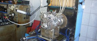
The fuel pump is adjusted on a special stand equipped with instruments for measuring the camshaft rotation speed, a graduated disk to determine the start of fuel supply, a measuring container to determine the amount of fuel supplied, as well as a variator drive that provides a smooth measurement of the rotation speed.
The speed mode is adjusted using a bolt screwed into the regulator body and limiting the tension of the regulator spring. To increase the number of revolutions corresponding to the start of the regulator’s action, the bolt is screwed in, and to decrease it is unscrewed. Each revolution of the bolt changes the engine speed by 30-50 rpm.
Setting the fuel injection start angle: 1 — distribution cover; 2 — lock washer; 3 - bolt; 4 — pump drive gear; 5 - splined flange; 6 — roller nut; 7 — bar; 8 — hatch cover; 9 - lock nut; 10 — adjusting bolt.
The uniformity of fuel supply across the pump sections and the cyclic supply adjustment are carried out using a nominal bolt. When screwing the bolt into the regulator body, the cyclic feed increases, and, accordingly, when unscrewing it decreases. To regulate the uniformity of fuel supply across the pump and plunger sections relative to the ring gear, a sleeve is used. When turning the sleeve to the left, the fuel supply increases, when turning to the right, it decreases.
The angle at which the fuel supply begins is adjusted by a pusher bolt along the fuel meniscus in the momentoscope, screwed to the pump fitting. To reduce the feed start angle, the screw is turned out of the pusher; to increase it, it is screwed in.
Checking the moment when the fuel injection pump starts supplying fuel is carried out in the following sequence:
1. Set the fuel control lever to maximum flow mode; 2. Disconnect the high-pressure tube from the fitting of the first section and connect the torque scope in its place; 3. Rotate the engine crankshaft in its operating direction until fuel appears from the momentoscope tube; 4. Remove some of the fuel from the tube and, slowly rotating the crankshaft, control the fuel level in the momentoscope tube; when the fuel begins to rise in the tube, stop rotating the crankshaft; 5. Unscrew the installation bolt and insert its reverse end into the same hole until it rests against the flywheel. Make sure the mounting bolt matches the hole in the flywheel. 6. Connect the high pressure pipe and screw the installation bolt into the hole in the back sheet. 7. Fix the fastening bolts of the splined flange, replace the hatch cover and adjust the axial clearance of the injection pump drive gear.
What needs to be removed from the MTZ 82 during repairs, and what shouldn’t?
During scheduled maintenance, current and major repairs, the work usually boils down to the following: remove worn consumables and damaged parts from the MTZ 82 and install new or restored ones in their place. Therefore, the need for dismantling arises quite often.
Nevertheless, you should not remove mechanisms and assemblies unless clearly necessary. The parts are worn in to each other, and unreasonable removal will lead to a reduction in service life.
- everything that can be repaired or serviced without dismantling is repaired directly on the MTZ 82 tractor;
- if diagnostics and repairs require a more thorough examination, the mechanisms are disassembled within the necessary limits, but no more;
- if it is not possible to carry out the work without dismantling, only in this case it is worth removing the equipment from the MTZ 82.
For MTZ 82 tractors, equipment and mechanisms are mounted on a semi-frame frame. Therefore, the process of how to remove 82 units from MTZ will consist of two key manipulations:
- disconnecting equipment;
- removing it from the frame.
Considering the weight of the units, lifting devices will be needed to remove them from the MTZ 82. These can be manual or electric hoists, beam cranes, special grips, etc.
The design of the Belarus 82 tractor is such that most of the mechanisms and equipment can be removed without additional dismantling of associated parts. But in order to remove some units, preliminary disassembly will be required. Let's take a closer look.
Installation advance angle of fuel injection (UOVT): step-by-step adjustment
The ignition should be set with the utmost care. Incorrect manipulations when turning the shaft will increase the time spent on maintenance and can lead to complete failure of the motor components.
"Visual" method
Locate the mark on the high-pressure fuel pump coupling and position the unit so that the mark is at the top. Rotate the engine until the friction wheel is set at 15-20 degrees. Loosen the bolts that hold the clutch in place and turn it to late injection counterclockwise. Unscrew the fuel supply pipe from the first cylinder, remove the remaining fuel in the recess and turn the clutch clockwise until fuel appears again. Tighten the bolts on the injection pump coupling.
How to remove the cabin from MTZ 82
Before removing the cabin from the MTZ 82, it is necessary to carry out preparatory work. At this stage, all equipment that can be detached is disconnected from the cabin. We recommend following the following sequence of work:
- remove the rear radiator trim;
- disconnect the control rods;
- remove the brake valve springs and brake pedal levers; disconnect and remove the clutch and brake pedals;
- disconnect the heating circuit hoses;
- disconnect the fastening to the brackets.
The next step in how to remove the cabin from the MTZ 82 is to disconnect the electrical equipment, namely:
- disconnect the wire from the battery to the starter;
- disconnect the wire supplying the instrument panel.
It is also necessary to disconnect the electrical wires supplying:
- tachometer;
- sound alarm;
- headlights.
The next step is to remove the floor of the MTZ 82 cabin, having first freed it from all equipment. Need to remove:
- rubber mat;
- box;
- Disconnect the fuel pedal.
Next, you need to unscrew all the bolts, nuts and other fasteners.
The fastenings are located both inside the MTZ 82 cabin and below. It is necessary to unscrew all fasteners before removing the cab floor.
Next, the block with the positioner control lever is disconnected and removed. The module is removed as an assembly.
At the next stage, the terminals and ground are disconnected, after which the battery can be removed.
If you have completed all the steps listed above, then you have disconnected all the equipment, fasteners and wires, so now you can remove the cabin itself from the MTZ 82.
How exactly to remove the cabin from MTZ 82?
It is clear that it is impossible to remove it manually alone. Additional equipment will be required for dismantling.
The easiest way to remove the cabin from the MTZ 82 is to use a beam crane, hoist or special lifting equipment with a crane or hanging hook.
Some farmers, in order to manually remove the cabin from the MTZ 82 at home, use homemade skids along which the structure simply slides to the ground. An example of such dismantling technology is presented in the video.
One of the disadvantages of such dismantling is the high probability of damage to the cabin, since it slides to the ground uncontrollably. But if you absolutely need to remove the cabin manually without using lifting equipment, then you can consider this option.
If you decide to remove the cabin from the MTZ 82, be sure to follow safety precautions. In some recommendations, the cabin is first raised with a lifting device and only then the wires are disconnected while the structure is suspended in the air. This is strictly forbidden, as there is a risk of the cabin falling. All dismantling work to disconnect fasteners, bolts, wires and remove pedals and levers must be performed before lifting the cab.
How to remove the engine from MTZ 82
How to properly remove the engine from MTZ 82? The entire engine is removed from the tractor for troubleshooting and repair, without disassembly. To remove the engine from the MTZ 82, the tractor is rolled out, i.e. the frame to which the main working units are attached, including the motor, is separated. To roll out the tractor, a special stand or rolling carts are used - they support parts of the machine, which roll out to the sides in blocks to open access to the power unit.
In practice, many farmers overhaul and repair the engine themselves, so choosing an alternative to repair stands or rolling carts becomes an important task for them. Is it possible to roll out the tractor and remove the engine from the MTZ 82 at home without the use of specialized equipment? Of course, we will continue to look at the main methods.
How to properly remove the engine from MTZ 82: sequence of actions
Before actually rolling out the tractor and dismantling the power plant, preparatory work needs to be done. It involves removing and disconnecting all hoses, wires and mechanisms that could be damaged during rolling. The sequence of actions is as follows:
- remove work equipment;
- remove the heating radiator (the cable, hoses going to the cabin, although long, are better to be disconnected too - before this you need to drain the antifreeze);
- remove all tubes and wires (return from the injectors to the tank, power cable from the batteries to the starter, wire going to the start, return from the pump, hose to the coarse filter, pipes of the metering pump (if the tractor has been converted), etc.;
- Unscrew all bolts on the side members.
Roll back the beam, front axle and side members together, as one block. To roll back the front axle and beam, you must first remove the radiator, otherwise it may be damaged. You need to bring a rolling cart under the front of the tractor - you can make it yourself from a frame welded from a metal angle or channel and a pair of wheels.
The next step in how to properly remove the engine from the MTZ 82 is to securely secure the motor to a hook, cable or any other lifting device. Often, a second tractor with a kun and even a two-hundred-liter barrel are used for these purposes.
Rolling options for the MTZ 82 tractor, which you can do yourself, are presented in the gallery.
After this, unscrew the motor mounting bolts and remove the engine from the MTZ 82. First, it must be suspended on a hook, hoist or other lifting device. Under no circumstances should you disconnect a hanging motor.
- First, the engine is simply fixed on a hook or hangers, but not lifted.
- Then disconnect all fasteners and hoses.
- Only after this can the engine be removed from the MTZ 82 by lifting it up.
How to remove a box from MTZ 82 at home
There are two ways to remove the box from the MTZ 82 - with dismantling the cabin and without removing the cabin. Let's look at each method and decide which one is more suitable for repairing a gearbox at home.
Method 1
First you need to remove the cabin of the MTZ 82 tractor; we wrote above how to do this. Next, perform the following steps:
- drain the oil from the gearbox and hydraulic system;
- disconnect the hoses from the hydraulic equipment housing on the right side of the tractor, the power regulator, and the differential lock clutch on the left;
- disconnect the wiring;
- unscrew the fastenings and remove the FDA drive transfer case;
- remove the control cover of the MTZ 82 box;
- unscrew the gearbox and clutch mounting bolts;
- remove the MTZ 82 box assembly as a single block.
After this, you can proceed directly to the gearbox overhaul, troubleshooting and repair.
Method 2
Despite the fact that most operation and repair manuals indicate the first method, you can remove the box from the MTZ 82 without removing the cab. Moreover, this may be even easier to do, since you can get by with rolling carts and not use lifting equipment.
Here is a step-by-step guide on how to remove the box from the MTZ without removing the cab:
- drain the oil from the hydraulics;
- disconnect all wiring from the front;
- disconnect the fuel hoses;
- unscrew the gas rods, etc.;
- remove the box cover (on MTZ 82 this is the transfer case);
- Unscrew the two bolts under the transfer case.
Injection pump device for MTZ - 80, 82
UTN-5, as the fuel pump for the Belarusian brand of tractors is called, is made of durable aluminum alloy and is available in two possible installation options - left and right, depending on the design features of the flange mounting. Throughout the entire body, it is divided into two cavity parts by a special partition, where in the lower cavity there is a shaft with a pump drive, and in the upper cavity there are separate sections of this pump.
You can read the full detailed structure of the high pressure fuel pump of the D-240 engine below
Fuel pump with regulator:
1 - pressure fitting; 2 - clamps; 3 - spring; 4 - discharge valve; 5 — valve seat; 6 - gasket; 7 — plunger bushing; 8 - plunger; 9 - plug; 10 — ring gear; 11 — rotary sleeve; 12 — regulator cover; 13 — rack rod; 14 — spring lever; 15 — regulator spring; 16 — enrichment spring; 17 — main lever; 18 — corrector housing; 19 — corrector rod; 20 — adjusting screw; 21 - intermediate lever; 22 — nominal bolt; 23 - bolt; 24 — regulator body; 25 — load axis; 26 - heel; 27 - coupling; 28 — heel axis; 29 — lever axis; 30 — regulator weights; 31 — thrust ball bearings; 32 — drain plug; 33 — cargo hub; 34 — shock absorber block; 35 — washer; 36 — bearing cup; 37 — oil deflector; 38 — control lever; 39 - cam shaft; 40 - plug; 41 — eccentric drive of the booster pump; 42 — flange for mounting the booster pump; 43 — adjusting washer; 44 — mounting plate; 45 — pump housing; 46 — oil supply hole; 47 — roller nut; 48 — splined bushing; 49 — mounting flange; 50 — pusher with roller; 51 — pusher adjusting bolt; 52 — spring plate (lower); 53 — plunger spring; 54 — spring plate; 55 — rack; 56 — bolt for bleeding; 57 — channel for fuel removal; 58 — bypass tube; 59 — bypass valve body; 60 - plug; 61 — valve ball; 62 — hole for fuel supply; 63 — channel for fuel supply; 64 - cut-off hole; 65 — inlet hole of the plunger sleeve; 66 - pin; 67 — hatch cover; 68 — adjusting screw; 69 — gasket; 70 - filler plug; 71 — adjusting screw; 72 — corrector spring; 73 - tightening screw.
How to remove fuel injection pump from MTZ 82 old and new model
Before removing the fuel equipment from the Belarus 82 tractor, you need to remove the injectors. They simply unscrew with a wrench.
Also, for convenience, it is worth disconnecting or at least loosening the fuel pipes. To avoid mixing up the hoses during installation, immediately place them in the correct order. Next, you need to turn off the valve on the fuel tank. After this, the return line and the hose going to the filter are unscrewed.
The next step is to disconnect the accelerator pedal.
After the preparatory work has been carried out, you need to unscrew the four nuts holding the fuel pump housing and then remove the injection pump from the MTZ 82.
To remove the fuel injection pump from the new MTZ 82, you need to additionally remove the cover to adjust the start of fuel injection and unscrew the three nuts on the studs under it.
Tell me how to reduce fuel consumption on MTZ-82.1
Good day everyone. Tell me how to reduce fuel consumption on an MTZ-82.1, 4UTNI pump, engine D-243, 2011 tractor. I work clearing snow, I fill up 40 liters - it only lasts for 5-6 hours. The old tractor ate 2 times less with the same work. What could be the matter?
remove the fuel and check the injectors on a stand
Is the air filter clean?
and how would you like it, under load, for the tractor to be fed with air? 40l in 5-6 hours is normal
and how would you like it, under load, for the tractor to be fed with air? 40l in 5-6 hours is normal
IN OUR ORGANIZATION WE JUST HAVE 2 MORE OLD MTZ WITH 240 ENGINES SO 20L IS ENOUGH FOR THE ENTIRE DAY (8 HOURS) WE DRIVE THE SAME WITH THE SAME KNIVES AND I CAN’T STAY IN 40.
and how would you like it, under load, for the tractor to be fed with air? 40l in 5-6 hours is normal
The man says that the old one ate less at the same job.
Is there any black smoke? How does it start? Works? Most likely it is indeed a fuel equipment.
Is the air filter clean?
BY THE WAY ABOUT THE FILTER. WHEN I REMOVED THE PAN AFTER BREAKING IN, THERE WAS A PIECE OF POLYETHYLENE AND SOME ROPE FLOATING IN THE OIL, IT CAME FROM THE FACTORY, THE ENGINE WORKED INTERMITTENTLY AND VERY HARD. AFTER WASHING THE FILTER THE INTERRUPTIONS HAD GONE BUT HARD WORK STAYED, SO I THINK MAYBE SOMETHING IN THE COLLECTOR IT'S SUCKS, THAT'S WHY THE CONSUMPTION IS LIKE THIS?
Is there any black smoke? How does it start? Works? Most likely it is indeed a fuel equipment.
NO SMOKE AT ALL, ONLY UNDER A LIGHT LOAD, STARTS GOOD, BUT RUNS HARD WITH THE OLD CAN’T COMPARE
remove the fuel and check the injectors on a stand
So I tell my mechanic this, but he resists, citing the fact that the tractor is new and everything is already adjusted at the factory. But my norm on it is 32 liters. For 8 hours I have to add hours to the trip in order to write off the diesel fuel
7-8 liters per hour is normal consumption when operating under load. Another thing is that your old tractors have worn-out equipment and do not pump as much fuel, but even under load they will not pull. Because of this, they work softer - even increasing the injection pressure leads to harsher engine operation. I have a Southern excavator that worked for more than fifteen years on fuel without repair - it only sniffed diesel fuel, but it didn’t carry any luck, in the mud even on the first one it withered and stalled (although when I took it from the fence on the third one it easily overcame any dirt) after repairing the fuel pump, the starting started from half a turn, the traction returned, I didn’t even believe it myself - in the same fields in the mud, third became the running gear - but the appetite also increased. In order for the horses to run, they need to be fed not only with air and a whip, but also with oats (here diesel fuel for the tractor).
7-8 liters per hour is normal consumption when operating under load. Another thing is that your old tractors have worn-out equipment and do not pump as much fuel, but even under load they will not pull. Because of this, they work softer - even increasing the injection pressure leads to harsher engine operation. I have a Southern excavator that worked for more than fifteen years on fuel without repair - it only sniffed diesel fuel, but it didn’t carry any luck, in the mud even on the first one it withered and stalled (although when I took it from the fence on the third one it easily overcame any dirt) after repairing the fuel pump, the starting started from half a turn, the traction returned, I didn’t even believe it myself - in the same fields in the mud, third became the running gear - but the appetite also increased. In order for the horses to run, they need to be fed not only with air and a whip, but also with oats (here diesel fuel for the tractor).
I agree, it means that the standard is coming out, you need to ask for another one if everything turns out to be in order with the fuel system?
Is there any black smoke? How does it start? Works? Most likely it is indeed a fuel equipment.
NO SMOKE AT ALL, ONLY UNDER A LIGHT LOAD, STARTS GOOD, BUT RUNS HARD WITH THE OLD CAN’T COMPARE
They all work like that when they’re new. For what reason, who knows? But your consumption is normal, which, believe me, isn’t much at all. If you have a dispute with a mechanic, shove your passport data in his face. And you shouldn’t open the pump if the tractor is under warranty. Then you’ll rake it yourself.
7-8 liters per hour is normal consumption when operating under load. Another thing is that your old tractors have worn-out equipment and do not pump as much fuel, but even under load they will not pull. Because of this, they work softer - even increasing the injection pressure leads to harsher engine operation. I have a Southern excavator that worked for more than fifteen years on fuel without repair - it only sniffed diesel fuel, but it didn’t carry any luck, in the mud even on the first one it withered and stalled (although when I took it from the fence on the third one it easily overcame any dirt) after repairing the fuel pump, the starting started from half a turn, the traction returned, I didn’t even believe it myself - in the same fields in the mud, third became the running gear - but the appetite also increased. In order for the horses to run, they need to be fed not only with air and a whip, but also with oats (here diesel fuel for the tractor).
How to remove a sleeve from an onboard MTZ 82
Removing the liner from the Belarus 82 onboard tractor is not so easy - this work is usually carried out in the factory using a special press and temperature. In theory, you can knock out the cartridge case using a sledgehammer or hammer. Of course, you need to hit them through a piece of wood. But even in this case, there is a risk of cracks appearing in the side.
You can try to free the cartridge case at home without knocking it out. To do this, a removable device is made from a regular car jack. Several washers are welded onto the jack, as in the figure below. One block of washers rests against the glass with the help of two crackers, and the second block is used for scrolling. Using such a simple puller, you can remove the liner from the onboard MTZ 82 without a hammer, sledgehammer, or even heat.
How to remove the PTO MTZ 82
To remove the power take-off shaft from the MTZ 82, you will need:
- drain the transmission oil;
- unscrew the four nuts from the studs;
- unscrew the six bolts (marked in the figure below) and move two of them (the side ones) into the special holes for extruding the cover;
- remove the hatch on top of the PTO housing, which is screwed to the cover with five bolts;
- under the cover there are two bolts that go into the brake bands; they need to be completely unscrewed;
- screw in the two bolts for extruding the cover, rearranged earlier;
- remove the PTO from the MTZ 82 by pulling it towards you.