How to correctly install clutch discs Yamz 236 double-disc
CLUTCH AND GEARBOX
Clutch - double-disc, dry, friction type, with peripheral coil springs. The YaMZ-236K and YaMZ-238 clutches are identical in design and differ only in the number of pressure springs. The YaMZ-238 clutch can be made in a sealed version.
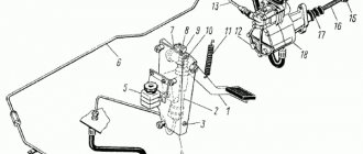
The clutch housing 16 (Fig. 26), stamped from sheet steel, with the pressure disk 19 assembly is installed on the engine flywheel 20, and the driven disks 21 are installed on the splined part of the gearbox input shaft. The front and rear driven discs are not interchangeable and are installed in a specific position, as shown in the figure. The driven clutch discs are clamped by a constant force of cylindrical pressure springs 17 between the engine flywheel, the middle and pressure discs. The YaMZ-236K clutch has eighteen pressure springs, the YaMZ-238 clutch has twenty springs. Thermal insulating gaskets 18 are placed under the springs on the pressure disk side. The pressure and middle drive disks are connected to the flywheel with four spikes located on the outer surface of the disks. When clamped, the driven disks transmit engine torque to the transmission input shaft.
The clutch is released by clutch 11. The clutch with the bearing, moving towards the engine, moves the pressure plate away from the driven disk, transmitting force through four rigid release levers 5. The working stroke of the clutch release clutch, taking into account free play, must be at least 18.2 mm (size “D”). The amount of free play is regulated by the clutch release mechanism. The thrust ring of the pull-out levers moves towards the gearbox by 27 mm due to the permissible wear of the friction linings.
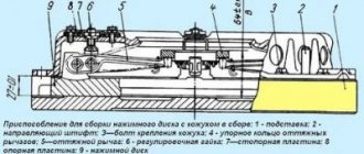
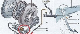
Rice. 26. Clutch YaMZ - 238: 1 - rod; 2 - ring; 3 - disc spring; 4 — bar; 5 — pull lever; 6 — fork of the pull lever; 7 — adjusting nut; 8 - spacer plate: 9 - locking plate; 10 — loop of the spring of the pull-out lever; 11 — clutch release clutch with bearing; 12 — lubricant supply hose to the clutch release clutch; 13 — clutch release fork; 14 — thrust ring of pull-out levers; 15 — clutch release fork shaft; 16 — clutch casing; 17 — pressure spring; 18 — thermal insulating gasket; 19 — pressure disk; 20 - flywheel; 21 — driven disks; 22 — middle drive disk; 23 - release spring; D—minimum release clutch stroke
Guaranteed clearances between the driven disks and the friction surfaces of the flywheel, middle drive and pressure disks when the clutch is disengaged as the linings wear are ensured by a mechanism for automatically adjusting the withdrawal of the middle disk, which consists of rods 1 fixed in each of the four spikes of the middle drive disk, split rings 2, to move along the rod which requires a certain force, thrust strips 4, which are bolted to the flywheel with the clutch casing, and disc springs
3, installed on the rod between ring 2 and bar 4.
When the clutch is disengaged, the pressure plate 19 moves back at least 2 mm and releases the rear driven disk
21. The middle drive disk 22, under the action of the spring 23, also moves back, until the ring 2 stops in the bar 4 through a disc spring, by an amount of 1.2 ± 0.1 mm, freeing the front driven disk.
As the clutch friction linings wear out, the middle drive disk, under the action of the pressure springs of the pressure disk, moves to the flywheel, the rings 2 rest against the clutch housing, moving along the rods 1 and maintaining the size between the rings and the disc springs.
When installing a clutch with a mechanism for automatically adjusting the release of the middle disk onto the flywheel, observe the following procedure:
1. Install the front driven disk.
2. Install the middle drive disk with rods.
3. Install the rear driven disk.
4. Install the pressure plate and housing assembly, securing it to the flywheel with eight short bolts.
5. Place split rings 2 onto rods 1 until they stop at the clutch housing.
6. Place four disc springs with the convex side facing the split rings.
7. Install four thrust bars and secure them with the housing to the flywheel using eight long bolts. After installing the clutch on the flywheel, make sure that
that the rings on the rods rest against the casing, providing a gap of 1.2 ± 0.1 mm between the rings and the disc springs when the clutch is engaged.
When the driven disc linings wear out, the end of the clutch release clutch will rest against the end of the gearbox input shaft bearing cover; in this case, replace the worn linings of the driven discs with new ones.
Lack of free play of the clutch will lead to failure of the pressure bearing and increased slipping of the driven discs. The free play of the clutch release clutch (dimension “A”) is adjusted by changing the length of the release mechanism rod or the length of the amplifier cylinder rod, depending on the design of the clutch release mechanism in accordance with the vehicle operating instructions.
Torsional vibration damping and power take-off mechanism
Power units can be equipped with a mechanism for damping torsional vibrations and power take-off (Fig. 3), designed to dampen resonant torsional vibrations and protect transmission systems from destruction.
The mechanism is installed on the engine flywheel and consists of a pressure flange 1, a driven disk 2 with friction linings and a mechanism for damping torsional vibrations, packages of disc springs 5 and stepped bolts 6.
Driven disk 2 is constantly pressed to flywheel 3 through flange 1 by packages of disc springs 5 assembled on stepped bolts 6.
The step bolts are screwed into the flywheel until they stop. When installing stepped bolts, sealant UG-6 TU 6-01-1285-84 is applied to their threaded part, tightening is carried out with a force of 49-59 Nm (5-6 kgcm).
The number of packages of disc springs and bolts is selected so that the friction moment they create allows the transmission of torque from the flywheel to the power take-off shaft up to 1700 Nm (170 kgcm).
When the driven disk is loaded with a torque of more than 1700 Nm (170 kgcm), the force of the springs is not enough to hold the driven disk and it rotates relative to the flywheel and thereby protects further kinematic connection from destruction.
During operation, the mechanism does not require maintenance.
Possible malfunctions of the driven disk during operation are similar to malfunctions of the clutch driven disk.
Premature slipping of the driven disk can be eliminated by installing additional packages of disc springs together with the bolt and further checking the friction torque in the following order:
1. Lock the engine flywheel.
2. Load the driven disk of the mechanism with a torque of less than
1700 Nm (170 kgcm). the disc should not rotate relative to the flywheel.
3. Load the driven disk of the mechanism with a torque of 1700... 1900 Nm (170... 190 kgf). The disk must rotate relative to the flywheel.
Clutch basket YaMZ-236/238 (MAZ) 238-1601090
Clutch basket for the YaMZ-236, YaMZ-238 (MAZ, K-700) engine. Clutch YaMZ catalog number: 236-1601090, 238-1601090. Pressure disk assembly YaMZ-238 (YaMZ-236)
The YaMZ-238/236 clutch basket is used on the K-700A; KamAZ-5410, Super-MAZ, KrAZ-260, KrAZ-6443, KrAZ-643701, KrAZ tractors; BelAZ-75485, BelAZ-75486, BelAZ-7540, BelAZ-75401, BelAZ-75400
The weight of the YaMZ clutch basket is 35 kg.
Buy clutch basket YaMZ 236 YaMZ 238 by phone 066-409-76-30, 067-611-18-32. Repair of YaMZ clutch basket.
Check with our managers for the current price for the YaMZ clutch basket!
The Remgidromaster online store offers clutch baskets for agricultural machinery.
The design and principle of operation of the YaMZ 238/236 clutch
The YaMZ-238K clutch is a double-disc, dry, friction type, with peripheral coil springs. Driven disks without damper device.
Clutch YaMZ-238 (YaMZ-238S) is a double-disc, dry, friction type, with a peripheral arrangement of cylindrical springs, with a damper device in the driven discs.
The YaMZ-236K clutch is a double-disc clutch, differs from the YaMZ-238 clutch in the reduced number of pressure springs - 24 instead of 28.
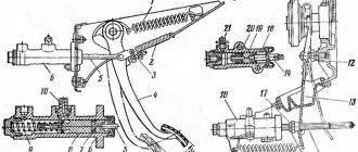
1— release spring; 2 - lock nut; 3 - adjusting screw; 4 — pull lever; 5 — pull lever fork; 6 — adjusting nut; 7 — lock washer; 8 — support plate; 9 - bolt; 10 — loop of the spring of the pull-out lever; 11— clutch release clutch with bearing; 12 - hose; 13 - fork; 14 - thrust ring; 15 — fork shaft; 16 — lever; 17 - finger; 18 — clutch housing hatch cover; 19 — clutch casing; 20 - spring; 21 — thermal insulating gasket; 22—“pressure disk; 23—flywheel housing hatch cover; 24 - flywheel; 25 — driven disks; 26 — middle drive disk; L—minimum stroke of the clutch release, taking into account free play; M is where the clutch is marked.
Each clutch modification is installed on the engine only with certain flywheels, differing mainly only in size A (Fig. 40) from the mating plane T3 to the working surface T. When assembling the engine, it is necessary to check the flywheel markings made in the casting on surface T2. On the YaMZ-236 engine, for a YaMZ-236K double-disc clutch, the flywheel is marked YaMZ-236-1005115-E, for a YaMZ-236 single-disc clutch, the flywheel is marked YaMZ-236-1005115-D.
On the YaMZ-238 engine, a YaMZ-238-1005115D flywheel was installed under the YaMZ-238K clutch; a flywheel marked YaM3-238-1005115-G was installed under the YaMZ-238 (YaMZ-238S) clutch. If two identical driven ones were installed in the YaMZ-238K clutch disc, then in the YaMZ-238 clutch the driven discs are not interchangeable with each other.
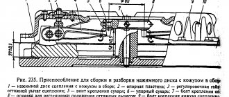
In connection with the introduction of a damper device in the YaMZ-238 clutch, the thickness of the middle drive disk was increased from 25 to 31 mm and the control dimension B in the pressure set was increased (see Fig.
120) between the working surfaces of the pressure plate and the thrust ring up to 64±D5 mm when installing the latter on the pull-out levers.
To make it possible to use the driven discs until the friction linings are completely worn out, the clutch release clutch is shortened by 10 mm. In addition, the YaMZ-238 clutch pressure plate has special stops for the release levers.
When introducing a damper device into the driven discs of the YaMZ-238 clutch, for the purpose of unification, the design of the YaMZ-236 single-plate clutch was changed. The previously installed driven disk has been replaced with the front driven disk of the YAME-238 double-disc clutch, marked on the friction lining with the number 238-1601130-B. The control dimension B of the pressure set has been changed and the clutch release coupling has also been shortened by 10 mm.
All clutch parts of the old design that are no longer interchangeable are supplied as spare parts along with parts of the new design. Below we consider the possibility of mutual use of parts in clutches of the old and new editions.
Pressure plates assembled with the YaMZ-236 clutch housing of the old design and the YaMZ-238K clutch with a control size of 56± ±0.5 mm can be adjusted in a special device (Fig. 121) to a control size of 65±0.5 mm for installation on engines , equipped with flywheels for clutches YAME-236 of a new design and YaMZ-238. The pressure set of clutches YAME-236 of the new release and clutches YAME-238 and YAME-236K with a control size of 64±0.5 mm cannot be readjusted to a control size of 56±0.5 mm due to the presence of stops on the release levers on the pressure disk.
A new design pressure kit with a control size of 64±0.5 mm can be installed without any changes in the YaMZ-236 clutch of the old design and in the YAME-238K clutch, but only with a clutch release clutch 50 mm long (shortened by 10 mm). The shortened clutch can be installed on clutches of both old and new designs. Thus, a pressure plate (a separate part) of an old design can be installed in clutches of both old and new designs, and a pressure plate of a new design with stops for the release levers can only be installed in a pressure set with a control size of 64 ± 0.5 mm.
Design features
The clutch of this model is usually installed on heavy, powerful equipment.
YaMZ 238 is a dry double-disc friction-type clutch; the mechanism’s cylindrical springs are peripherally located.
The engine power and the actual design features of the mechanism very often lead to the fact that an incorrectly configured clutch can easily fail. In order to avoid breakdowns, it is necessary to diagnose and adjust the YaMZ 238 clutch at least once every six months.
Required Clutch Maintenance
Every time you start maintenance of the clutch, you must adhere to a strict sequence so as not to miss anything important and notice the problem in time:
- The first step is to check and, if necessary, adjust the free play of the clutch responsible for engaging the clutch (the gap should be 3.2–4 mm).
- Next, you need to check the mechanism for lack of guidance. (check is carried out with the engine running in first gear and with the clutch disengaged).
If you find out that the value is far from the maximum norm, there is only one way out, adjusting the YaMZ 238 transmission.
Adjusting the MAZ clutch
In previous articles, we discussed the issue of repairing the MAZ clutch and its design.
Today we offer some useful tips to help you adjust the MAZ clutch.
We will also tell you how to bleed the clutch on a MAZ.
Instructions for adjusting the MAZ clutch
A truck clutch is a double-disc friction-type device that is installed in the truck crankcase. function - disconnecting the crankshaft of the truck engine from the gearbox. Also, the clutch smoothly connects the elements (gearbox and engine crankshaft) when changing gears. However, over time, the mechanisms wear out. Therefore, the MAZ clutch is adjusted. To do this, we recommend buying:
- Socket and open-end wrenches;
- Vernier calipers and ruler.
So, adjusting the MAZ clutch is done as follows. First you need to ensure the maximum correct gap between the surfaces of the mechanism. To do this, we will adjust the amount of waste of such an element as the drive disk. Note the gap between the adjusting nut and the end of the valve body cover. We also recommend that you adjust them.
Adjusting the MAZ double-disc clutch requires patience. Therefore, we continue further. We proceed to dismantling the flywheel housing and its hatch cover. All this is necessary to vary the amount of withdrawal of the middle disk (driver). Adjusting the MAZ clutch at this stage is done as follows:
- Engage the clutch;
- Set the gearshift lever to neutral;
- Turn the engine flywheel;
- Unscrew the lock nuts of the screws;
- Screw the 4 screws into the middle drive disk until they stop.
The adjustment of the MAZ double-disc clutch is still not completed.
Next, we continue to rotate the flywheel, after unscrewing the screws 1 turn. Then we secure these elements with locknuts. There is one point - adjusting the MAZ double-disc clutch requires constant holding of the screw with a tool. This way the adjusted gap cannot go astray. We continue with the adjustment. Using a ruler, measure the gap between the nut and the end of the rear valve cover. Remember that it should not exceed 3.3 mm.
Adjusting the MAZ double-disc clutch involves working with exactly this nuance. To adjust the gap, loosen the locknut of the adjusting nut. After fixing the required gap (3.3-3.7 mm), tighten the fasteners. That's it, the adjustment of the MAZ double-disc clutch is done.
How to bleed the clutch on a MAZ?
Adjusting the MAZ double-disc clutch does not take much time. However, problems sometimes arise with bleeding the clutch.
Before thinking about how to bleed the clutch on a MAZ, we advise you to make sure that this procedure is necessary. One of the main reasons that the PSU needs to be pumped is poor gear shifting. That is, in this case, the clutch does not engage completely, since air has entered the vehicle’s hydraulic line. Therefore, all car owners need to know how to bleed the clutch on a MAZ.
Here are a few instructions to help you.
Before pumping the MAZ clutch, gradually fill the hydraulic drive reservoir with fluid to the level of one and a half centimeters (1-1.5 cm).
It is important to clean the cylinder exhaust valve of any contamination. Remove the protective cap from its head. We put a rubber hose on the element. Usually it is included in MAZ accessories.
Service
Maintenance of this mechanism is carried out as follows:
- Carry out an external inspection of the pedal and, if necessary, adjust its free play.
- Bleed the hydraulic drive.
- Carry out diagnostics of the crankcase fastening elements and, if necessary, tighten the nuts.
- Carry out an external inspection of the tension spring device, lubricate the bearings and hydraulic coupling.
- Check the functionality of the clutch switch and the shaft sleeve.
- Inspect the fork and clutch pedal for wear and damage.
- Check the operation of the mechanism by changing the gears of the vehicle on the spot and during acceleration.
- Eliminate incorrectly set gaps between support rings and washers.
- Eliminate leaks in the system and lubricate all cylindrical elements with a special liquid.
- Check the gap between the rods and the piston part of the main cylindrical device.
How to make adjustments
Actions when adjusting the MAZ clutch:
- Adjust pedal free play. To do this, you need to put your foot on the pedal and squeeze the gas all the way. If necessary, reduce or increase the stroke of this device.
- Release the pedal and measure the distance to the lower mark of the coupling mechanism.
- The maximum stroke amplitude should not exceed 16 cm.
- Tighten all fasteners.
- Measure the pedal free play.
After the driver has adjusted the clutch mechanism, it is necessary to adjust the MAZ clutch basket:
- Place the transport on a special platform.
- Unscrew the mounting bolts that connect the gearbox and the car body.
- Remove the gearbox.
- Unscrew the screws of the push-type disk and remove it.
- Inspect the basket and replace damaged or worn parts.
- Adjust the position of the paws.
- Using the adjustment handle, set the paws to the positions shown in the MAZ repair manual.
- Tighten all mounting screws until they are secure.
- Reassemble the mechanism by repeating all steps in reverse order.
Clutch of YaMZ-236, YaMZ-238, YaMZ-7511 engines
The clutch is double-disc, friction, dry, with peripheral springs. Driven disks with a diameter of 400 mm, with a spring-friction type torsional vibration damper, with asbestos-based friction linings.
The engagement clutch with a special angular contact bearing moves towards the engine when engaged.
Specifications
parts, kgMoment of inertia of the driven disk, kg m s2 Dimensions of the driven disk spline, mm
| YaMZ-236K | 700 | 70 | 0,09 × 2 | 42 × 34 × 6 |
| YaMZ-238 | 920 | 70 | 0,09 × 2 | 42 × 34 × 6 |
| YaMZ-238N | 1275 | 70 | 0,09 × 2 | 42 × 34 × 6 |
| YaMZ-236KM | 700 | 71,4 | 0,1 × 2 | 42 × 34 × 6 |
| YaMZ-238M | 920 | 71,4 | 0,1 × 2 | 42 × 34 × 6 |
| YaMZ-238NM | 1275 | 71,4 | 0,1 × 2 | 42 × 34 × 6 |
The most common causes of clutch system failure
The human factor can lead to premature failure of a given unit. Here are several factors that affect clutch life reduction:
- Aggressive driving style. You should not constantly press and release the clutch pedal sharply - this will cause the friction linings to quickly fail.
- Driving under increased loads.
- Incorrect towing. Inexperienced car owners often keep the pedal half-pressed when towing. It is also not recommended to tow vehicles much heavier than your car.
- Driving with the clutch pedal half depressed.
- Sharp starts and too smooth at high speeds.
- Many beginners often keep the clutch depressed during short stops (for example, at a traffic light). This should not be done, since in this position the release bearing is under constant load, and this leads to its premature failure.
The working life of the coupling is quite long and ranges from 100 to 150 thousand km. When used correctly, the mechanism is quite reliable and reaching the top level is quite possible.