Features of installation and differences between crane and crane runways
Crane tracks provide a minimum area of the involved working space, since the main structures are located at a height. The tracks are installed on steel or reinforced concrete crane beams, which are mounted to the cantilever elements of the load-bearing columns.
Ground crane tracks require preparation of the base - soil, utilities and drainage, since the crane tracks are located slightly higher or at the level of the main soil.
Depending on the type of crane that will be installed in production, the following are distinguished:
- Suspended crane tracks
- used for cranes with a lifting capacity of up to 10 tons or more. The tracks are attached to the walls and ceiling. The load axis is located in a vertical plane. - Supporting device for crane tracks
- for cranes with a lifting capacity of up to 50 tons or more. The installation of tracks is carried out on support beams and columns.
Crane tracks consist of main and additional components. The main components include crane beams and rails. Additional components include end stops, fasteners, buffers and pad.
The supporting beam firmly holds the crane tracks due to various types of fastenings: brackets (in some cases interlocked by welding), clamping pads, threaded connections. Among these fasteners, the most practical are dismountable, which allow you to quickly replace the damaged area.
The rails, in turn, differ in size, depending on the load-carrying capacity of the equipment. For cranes with a lifting capacity of more than 30 tons, KR100, KR120, KR140 rails are used. Double-girder cranes, which are designed to lift weights from 10 to 30 tons, use rails of the KR70, KR100 grades. In the case of small-tonnage cranes (up to 10 tons), KR70 rails are used. For lifting devices of the hoisting and transport type, KR brand rails are produced, where the width of the rail head is indicated after the letter designation, for example KR-70.
Braking buffers are installed at the extreme points of crane tracks. According to the device, they are divided into impact (absorbs the kinetic energy of movement) and non-impact (due to rolling on a rise or stop). These two devices can also be combined.
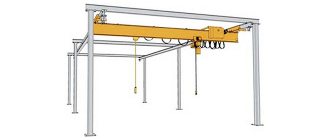
Overhead crane tracks for overhead crane
Ground tracks of gantry crane
Crane tracks of overhead bridge crane
On a note!
For the development, creation, installation and operation of crane tracks, there are standards in accordance with SNiP 3.08.01-85. It displays all the stages and requirements for the product. When commissioning and accepting crane tracks into operation, a report is drawn up. It contains parameters for track leveling, data from geodetic surveys of the transverse profile of tracks, and determination of the degree of resistance to current propagation along the grounding contour of the crane track.
What equipment is being designed for?
The company plans sites for lifting equipment, which is presented as:
- bridge cargo lifts;
- gantry crane;
- suspended units (crane - beams).
To ensure safe operation of bridge lifting devices, special metal guides are installed. The cylindrical rims of the running bogies will move along them. Crane directions are attached to embedded metal elements of concrete (reinforced concrete) beams. Rail joints are designed in such a way that they are staggered. This technical solution ensures an even load on the metal threads.
Ground roads for gantry cranes are laid taking into account a significant distance between the rails from each other to ensure reliable stability of the structure.
For overhead lifting devices, the company provides directions that:
- mounted on special overpasses (in open areas);
- suspended from ceiling trusses (inside the building).
General requirements for modern crane tracks
When drawing up a project for a ground crane runway, the following information is included:
- type, length and cross-section of rail sleepers;
- distance between sleepers;
- options for fastening rails to sleepers and between each other;
- additional layers, gaskets in the gap between the sleeper and the rail;
- type of gaskets and how they are installed;
- the size of the gap (gap) between the rails;
- what material is used as the ballast layer and its size;
- permissible minimum curve radii on curved sections of the crane runway;
- the value of the maximum permissible total longitudinal slope;
- level of elastic subsidence under the crane wheels and tolerances for track width;
- difference in height of rail heads;
- type of design of dead-end stops and grounding of the rail track.
In order to ensure safety for others and the operating personnel of the crane from electric shock, in accordance with the requirements of the Crane Rules and SN 102-76, electricity is diverted into the grounding circuit.
At the stage of checking the condition of crane tracks, if there are dents on the heads of the tracks or sagging ends of more than 3 mm; cracks in joints, rail heads and necks; the presence of metal corrosion to a depth of more than 3 mm; thinning and wear of rail heads greater than 6 mm in height or 3 mm in width, other damage, further use is prohibited.
Advantages of PODEM LIGA SERVICE LLC
Our company is engaged in the installation of rail tracks under cranes in a professional, qualified and high-quality manner. We offer a wide range of services not only for the installation of various equipment, but also for the maintenance of structures. All work is guaranteed to be completed in accordance with technical specifications and requirements, with high quality and on time.
The structures installed by our highly qualified specialists are characterized by increased strength, reliability, and safety. The uninterrupted operation of our equipment is the key to the success of your company.
Construction of crane tracks for overhead cranes
Depending on the project, the overhead crane can be located on support or suspended type crane tracks. In the manual Series 1.426.2-7 “Crane steel beams for overhead supporting cranes
Issue 1 “Split beams with a span of 6 and 12 meters for single-girder cranes with a lifting capacity of up to 5 tons” for single-girder cranes with a lifting force of 5 tons, a wide-band I-beam 30Ш1 is used as a crane beam. The upper structure is made of a square of solid section 50*50 mm, which is fixed to the beam by electric welding with an intermittent seam. In Issue 3, “Split beams with a span of 6 and 12 meters for general purpose cranes with a lifting capacity of up to 50 tons,” a welded beam with a height of 440 mm is specified for overhead cranes with a lifting capacity of up to 10 tons with a column spacing of 6 meters. To install a rail with a wide base and fastening elements for the upper structure, a width of 320 mm is provided. Typically, a 40Ш1 beam with reinforcement with stiffeners or 50Ш1 is used. Crane rails or narrow-gauge guides are used as tracks. Assembly and installation is carried out using welding and various types of fasteners.
Depending on the lifting capacity of the crane, different sizes of the crane beam are selected. Most often, an I-beam is used with a shelf width of 200 mm, and its height is 600 mm and above.
support type crane tracks
use columns or crane beams as the substructure and rails and fastening components as the superstructure. An overhead crane on free-standing columns is often installed together with the laying of the production premises itself, since it is necessary to prepare the foundation - the foundation. When designing a foundation, the top layer of soil is removed, a drainage system is organized, and sand and crushed stone are laid in layers. Then the electrical communications are connected.
Mostly single-branch columns are installed, since double-branch columns, although more stable (more rigid), are difficult to manufacture, which affects the price of the product. To increase rigidity, an I-beam with a large cross-section in height is used; its width is of a standard size. In some cases, the column heads are connected with a spatial truss to provide bending rigidity, and the crane beams are placed on consoles. Crane beams are attached to reinforced concrete walls. The length of this path is somewhat shorter than the crane path on columns. The advantage is the preservation of a larger working area in production.
Suspended structures for overhead cranes
Due to their simplicity and low price, they have gained great popularity among many enterprises. They are often used in already built premises, which provide sufficient height and strength of walls and ceilings for attaching floors and suspended trusses.
For open (street) and closed production sites, overhead crane tracks with climate class U1 are used. According to it, the materials from which the tracks are made are resistant to temperature changes in the range from -25 to +40 degrees Celsius. For conditions of extremely low temperatures (down to -40 degrees), frost-resistant components are selected.
Suspended crane tracks are designed for crane lifting capacity of up to 10 tons or more. This type of crane moves along the inner bottom flange of the beam. However, it is permissible to place several cranes on such tracks. The movement of the crane is possible along the entire length of the path, due to the absence of intermediate support structures. Special attention is paid to the installation of suspended tracks.
According to Series 1.426.2-6 “Beams of overhead transport tracks” the cross-section of beams and methods of fastening to floor structures are regulated. Thus, hot-rolled I-beam 24M, 0M, 36M, 45M according to GOST 19425-74 is used as a crane beam. The M index in a series of beams means reinforcement of the shelf to withstand loads from the wheels (rollers) of suspended carts. The beam is fastened to the ceiling using bolts through a special “chair” element in a one-piece type with a truss. This special “chair” provides adjustment of the crane beams in height and span width.
Construction of ground crane tracks for gantry cranes
Crane tracks conventionally consist of a lower and upper structure.
The lower one involves the creation of a special soil bed and the organization of a drainage system. Upper - installation of sleepers, rails and joints. The upper one also includes a ballast prism in the form of sand or crushed stone. Sand ballast - for cranes with a lifting capacity of 5 tons (with a layer thickness of more than 300 mm). Crushed stone-gravel prism for cranes with such tonnage can have a slightly smaller thickness - from 250 mm. For cranes with greater lifting force, the ballast prism should be 400 mm or more. The ends of the sleepers must be overlapped by such an embankment by at least 200 mm.
For crane tracks of gantry and semi-gantry cranes located on the ground type, the installation rules of GOST R 51248-99 are provided. It provides requirements for installation teams that are certified for this type of activity. To get started, you should create a project that includes:
- passport and design of the crane runway (including its arrangement);
- a copy of the general construction plan;
- documentation on the availability of crossings for ground transport through crane tracks.
It also includes data on the track width, the length of the crane tracks, and places for parking the crane.
Preliminary geodetic preparation is carried out with an assessment of the nature of the soil and the location of future crane tracks. Surveyors will calculate possible soil subsidence and help adjust the parameters of crane tracks.
On a note!
Mobile jib cranes can also be mounted on crane tracks. This depends on the specifics of the tasks of individual production. The installation principles and design of crane tracks for jib cranes are similar to those shown above for ground-based cranes.
The crane runway is divided into two main parts:
- top;
- lower
The first layer is an earthen embankment, a kind of cushion for good shock absorption, then the rail track is laid. Here, the laying technology differs significantly from the laying of a traditional rail track. After the rail track, grounding and electrical equipment have been laid, it is necessary to form a drainage system. Most often, crushed stone, gravel (the size of the fraction does not matter), sand or a mixture of sand with a small fraction of gravel are used for this. It is very important that this layer does not contain debris. Experts call this layer in the structure of the crane runway ballast.
Ballast ensures the stability of the rails during the movement of the crane track.
Slabs are used as under-rail supports. It can be:
- concrete;
- reinforced concrete structures;
- wooden beams.
It is imperative to use welding work to firmly fix the rails in the crane track system. So, when laying rails on sleepers, in addition to mechanical fixation (using steel wire), it will be necessary to strengthen the fixation using hot work.