The testing methodology for overhead and gantry cranes is regulated by federal norms and regulations in the field of industrial safety “Safety Rules for Hazardous Production Facilities Where Lifting Structures are Used”, approved by Rostechnadzor Order No. 533 dated November 12, 2013.
Static and dynamic tests of the crane are carried out by loading it, measuring elastic and residual deformations of the crane span and checking the condition of its brake systems, as well as the lifting drive.
The crane is loaded during testing in two ways: control weights or hydraulic loaders. Each of these methods has its own advantages and disadvantages. The advantage of using control loads is the ability to conduct dynamic tests in full, including moving the load along the bridge beam and moving the loaded crane along the span along the crane tracks. The main disadvantage of this method, which makes it practically unsuitable for testing heavy-duty cranes, is the need for heavy and bulky test loads.
Due to this lack of test loads, the most common way to test medium and heavy-duty cranes is to use significantly lighter and more compact hydraulic loaders.
Hydraulic loaders provide simple and convenient adjustment of the loading force during both static and dynamic tests of the crane. However, the use of hydraulic loaders requires the mandatory installation of an anchor in the foundation with an embedded element (anchor rod), with which the loader hydraulic cylinder body engages. Accordingly, dynamic tests using a hydraulic loader are possible and are carried out only in relation to the crane's hoisting drive. In this case, the position of the crane during testing is determined by the location of the anchor rod.
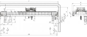
A typical diagram of a hydraulic loader connected to an anchor rod, with the crane located at zero level, is shown in. When the crane is located on the second level, during testing the hydraulic loader is connected to the anchor rod by means of an anchor chain through an opening in the ceiling of the second level.
Selecting a hydraulic loader
Until now, the guideline when choosing a hydraulic loader is often the technical specifications TU 24.00.13.032-87, issued back in the USSR, which contain only 4 standard sizes of hydraulic loaders for testing cranes with a lifting capacity from 16 to 500 tons. Due to the huge variety of designs and lifting capacities of existing bridge and gantry cranes such a small number of standard sizes included in the design documentation of structures and the cranes themselves is technically and economically unjustified. Therefore, in 2014, AVA Gidrosystems JSC developed and registered technical specifications TU 3116-001-33103904-2014, containing 15 standard sizes of hydraulic loaders for testing cranes with a lifting capacity from 0.8 to 560 tons (see Table 1). In addition, in each standard size of the hydraulic loader there are 2 versions: version “C” - only for static tests and version “D” - for static and dynamic tests. The presence of two versions is due to the fact that when carrying out dynamic tests, the crane drive lifts and lowers the hook under load; accordingly, a hydraulic loader is required with an increased hydraulic cylinder stroke, pump flow and hydraulic station tank capacity compared to the “C” version.
For cranes with a lifting capacity of up to 10 tons, TU 3116-001-33103904-2014 includes, along with hydraulic loaders with an electrically driven hydraulic station, a simpler and cheaper hydraulic loader NG-0.13R, equipped with a hand pump. The disadvantages of the hydraulic loader NG-0.13R in comparison with hydraulic loaders with an electrically driven hydraulic station are:
- significant physical stress on the tester when working with a hand pump,
- a significant increase in the time required to build up the test force and tests in general,
- impossibility of carrying out dynamic tests.
For versions “D”, TU 3116-001-33103904-2014 specifies the range of strokes of hydraulic loader cylinders. This allows specialists who know the characteristics of the crane lift drive subject to dynamic testing (in terms of the required hook stroke) to select and order a hydraulic loader with a minimum but sufficient hydraulic cylinder stroke, i.e., the most compact and economical.
Thus, the technical conditions TU 3116-001-33103904-2014 provide the choice of a hydraulic loader with maximum consideration of both technical and economic requirements for testing cranes.
The following procedure for selecting a hydraulic loader is recommended: a) based on the nominal load capacity of the crane under test (for a group of cranes - the largest value), multiplied by 1.25, the test force during static tests is determined. Then the closest standard size of hydraulic loader is selected, the pulling force of which is not less than the required test force; b) according to the required type of testing, the design is selected: “C” (static tests only) or “D” (static and dynamic tests); c) when choosing version “D”, if the required hook stroke is known, the required stroke of the loader hydraulic cylinder is determined, which must exceed the hook stroke by at least 20%. If the required hook stroke is not determined, then the hydraulic cylinder stroke is taken to be the maximum from the range specified in the technical specifications; d) for a crane that has auxiliary hoists, or for a group of cranes with significantly different lifting capacities, situations are possible where the test forces required for some hoists or cranes are less than the minimum value of the range of pulling forces selected in paragraph a) of the hydraulic loader. To ensure the necessary accuracy of testing these hoists and cranes, from the size range in table. 1 an additional hydraulic cylinder with the required range of pulling forces is selected and included in the delivery package of the hydraulic loader; e) during dynamic tests for all crane lifts subject to testing, it is verified that the minimum lifting/lowering speeds of the hooks provided by the electric drives of the crane do not exceed the maximum speed value specified in the technical specifications for the selected hydraulic loader. If such an excess is established, then from the number of hydraulic power stations available in the technical specifications, a version with a higher pump flow is selected and included in the hydraulic loader set.
Examination of lifting equipment
One of the types of dangerous equipment used on construction sites, enterprises, workshops, ports, docks are lifting mechanisms. According to the appendix to Federal Law No. 116, they must be regularly examined for operational safety. Based on the results of the inspection, an official conclusion is issued on the possibility of further use, repair or write-off of the equipment.
offers services:
- Industrial safety examination of bridge, gantry, tower and portal cranes. The main methods for diagnosing equipment are: visual and ultrasonic testing, coercimetry, magnetic particle flaw detection.
- Electrical safety inspection of crane tracks is carried out before they are put into operation, as well as after the expiration of the previously conducted expert assessment. Based on the results of the research, the commission issues a passport indicating the shortcomings or their absence, the possibility of further operation and the time of the next technical inspection.
Completeness
The basic set of hydraulic loader includes a hydraulic cylinder with eyes and axles for coupling with an adapter link and an anchor rod, a hydraulic station and a set of connecting hoses with quick-release connections. In version “D” the hydraulic cylinder is necessarily equipped with an emergency limit switch that limits the stroke of the rod. The hydraulic cylinder axes of large size loaders, starting with NG-0.8, are equipped with screw drives for ease of coupling. As stated above, in some cases an additional hydraulic cylinder is included in the basic kit.
To test a crane using a hydraulic loader, in addition to the basic kit, you need a set of accessories, the composition of which depends on the conditions in which they are carried out. In some cases, a platform is allocated for testing (at the end of the travel of the crane bridge beam), on which the hydraulic loader is constantly in the working position. Under such conditions, the delivery package of the hydraulic loader includes (or is provided by the customer) an anchor rod, a transition link between the hook or suspension of the crane and the hydraulic cylinder rod, and a stationary service platform equipped with a clamp and turnbuckles to hold the hydraulic cylinder in a vertical position.
In most cases, after testing the crane, the hydraulic loader must be removed from the test site and taken to its storage location. In addition to the transition link and anchor rod, the hydraulic loader kit includes a support device with a clamp and turnbuckles, a rolling service platform and a trolley for transporting and storing the hydraulic cylinder. Small hydraulic loaders according to TU 3116-001-33103904-2014, up to standard size NG-0.25 inclusive, are structurally designed in the form of a hand trolley with a hydraulic station and a cradle installed on it, on which a hydraulic cylinder is attached during transportation and storage.
Technical examination
All load-lifting cranes and load-handling devices that are subject to industrial safety rules are subject to periodic inspection in accordance with the requirements of regulatory documentation of the Russian Federation.
Technical inspection of lifting machines can be scheduled or unscheduled. All lifting mechanisms must undergo routine technical inspection:
- Partial technical examination (PTO) – at least once a year
- Full technical examination (PTO) - at least 1 time every 3 years
Unscheduled technical inspection of lifting machines is carried out:
- Based on the results of installation of the crane, transfer to a new location.
- When carrying out reconstruction: replacement of movement units, lifting, re-equipment of the trolley for another load-handling mechanism (grab, magnet), reduction/increase in span, increase in load capacity.
- Repair of load-bearing metal structures of the crane
- Replacing the hook suspension
- Carrying out major repair work
Technical inspection of lifting mechanisms is a mandatory set of works during operation. Properly carried out inspection allows us to ensure further safe operation and trouble-free operation.
contents .. 1 2 3 ..TICKET No. 2
1. Purpose of static testing of overhead crane
Checking the strength of the overhead crane and its individual elements.
The procedure for carrying out static tests is as follows:
176. Static tests of an overhead crane are carried out as follows. The crane is installed above the supports of the crane track, and its trolley (trolleys) is installed in a position corresponding to the greatest deflection of the bridge; the first high-altitude notation of the position of one of the main beam chords is made (using a metal string, an optical device or a laser range finder). Then a control load weighing 125% of the nameplate lifting capacity is lifted by a crane to a height of 50 - 100 mm, a second high-altitude notch is made of the position of the same main beam belt and the crane is maintained in this position for 10 minutes. If an arbitrary lowering of the raised load is detected, the tests are stopped and the results are considered unsatisfactory.
After at least 10 minutes, the load is lowered, after which a third high-altitude notch is made of the position of the same main beam chord. If the value of the third measurement coincides with the first, there is no residual deformation of the crane bridge, and the tests were successful.
If there is residual deformation (lack of equality of the first and third measurements taken), resulting from testing the crane with a load, the crane should not be allowed to operate until a specialized organization has clarified the causes of the deformation and determined the possibility of its further operation.
2. List of goods prohibited from being lifted by cranes.
When operating lifting machines, it is prohibited to lift loads:
— the mass of which exceeds the permissible load capacity for a given flight;
— unknown mass and it is not possible to determine it by any available method;
- simultaneously cargo and people;
— lift loads that are in an unstable position;
— tear off frozen loads, covered with soil, or buried by other loads;
- pull up loads with oblique tension on the lifting ropes, pull back loads when lifting;
— dangerous and toxic cargo without written permission from the person responsible for the safe operation of cranes or from the owner of the cargo;
— any cargo in the absence of a work permit when working near power lines, without receiving targeted instructions, or in the absence of a person responsible for the safe performance of work with cranes;
- any cargo when brakes, instruments and safety devices are disabled or malfunctioning.
3. Reasons for twisting the cargo rope.
1. The presence of internal stresses in the rope generated during its manufacture.
2. Incorrect reeving of a new rope after replacing a worn one.
Recommendations for eliminating twisted cargo rope branches
Based on the experience of specialists from JSC KAZ
After replacing the load rope on the crane with a new one, during the process of lifting the load, cases of twisting of the rope branches may occur due to ...... (see above).
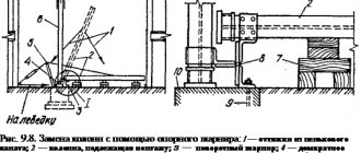
To eliminate twisting of the cargo rope branches, it is recommended to unwind it from the coil and lay it out straight, protecting it from contamination. If the size of the production area does not allow this due to the length of the rope, then it is necessary not to wind the cargo rope immediately from the coil onto the cargo winch drum, but to first wind it onto the intermediate drum, cutting off the required length and allowing the end of the rope to unwind freely. When winding the last 1/3 of the rope from the coil onto the intermediate drum, the end of the rope must be forcibly untwisted in the opposite direction. The intermediate drum for winding the cargo rope can be manually driven (Figure 1).
When winding the rope from the intermediate drum to the cargo winch, the intermediate drum must be braked so that the rope is wound onto the cargo winch with a force of 0.5 - 1.0 t (Figure 2).
When winding a rope onto a drum, it is necessary to pay attention to the correct placement of the first layer so that the turns lie close to one another and tightly wrap around the drum. It is advisable to wind the rope onto the winch drum and unwind it smoothly, without jerking, in order to prevent damage to the structural integrity of the rope when it is bent on the blocks and drum.
When putting a new rope into operation, it is necessary to run it in for 20 - 30 cycles with a load of 10% of the nominal one. To eliminate twisting of the cargo rope branches, it is necessary to install the crane on outriggers, extend the boom and “pull out” the rope. This operation also reduces the buckling of wires in the form of loops, helps to equalize the tension between the strands of the rope, which as a result increases its durability.
It is recommended to pull out the rope with a boom length of 14.0 m and pulley multiplicity n=8 with a gradual increase in load (50%, 75%, 100% of the nominal) at the corresponding reach of the load characteristic used at a height of 100 - 200 mm from the ground level with holding in this position for 10 - 15 minutes over two to three work shifts.
ATTENTION! If it is not possible to eliminate the twisting of the rope using the specified method, then the following operations must be performed:
1. lift the same load to a height of 100 - 200 mm from the ground level, allow it to rotate spontaneously, holding it from rapid rotation, count the number of revolutions “n” made until it stops, lower the load;
1. Lower the boom to a position where the distance between the boom tip and the ground level is 1.5 - 1.8 m, and the hook suspension should lower to the working platform. To provide access to the boom head, it is possible to further extend the boom sections;
2. remove the wedge bushing from the boom head;
1. remove the clamp from the rope;
1. knock out the wedge from the wedge bushing and remove the rope from the wedge holder;
1. remove the thimble with the end of the cargo rope from the boom head and release the cargo rope from the hook clip;
2. Rotate the thimble with the rope around the axis of the rope in the direction of twisting the rope branches. The number of revolutions of rotation of the thimble “N” should be 1 - 5 revolutions greater than the number of revolutions of twisting the branches of the rope “n”, measured in step 1;
1. pass the cargo rope through the hook suspension blocks, depending on the required reeving ratio, install and secure the thimble with the rope on the boom head;
2. raise the boom;
1. lift the maximum permissible load at the corresponding reach of the load characteristics used to a height of 100 - 200 mm from the ground level and hold the load in this position for 10 - 15 minutes;
1. Perform 5-8-fold lifting (lowering) to a maximum height of a load weighing 4.0 tons at a reach of 8.0 m with a boom length of 21.7 m.
1. When re-twisting the rope branches, operations 1 - 11 must be repeated.
Addition to recommendations:
if the end of the rope is on the hook (odd reeving), then twist the end in the direction of twisting; if on the head (even reeving), then in the opposite direction.
Reeving the rope (i.e., arrangement in blocks) according to the passport. Fastening the end in the bushing - the working end must enter along the straight side of the trapezoid of the body - the axis of the rope must coincide with the axis of fastening the bushing to the crane structure.
—————————————————————————————————-
contents .. 1 2 3 ..