DT-75 is a type of crawler tractor that is relevant for use in agriculture. This equipment is distinguished by quality of workmanship, ease of operation, and maintainability. This version of auxiliary equipment has existed for several decades. During this time, it was repeatedly modified to improve its performance properties. Taking this into account, various brands of engines can be found on this equipment.
In one housing there is a gearbox and a rear axle, while the latter element has two single-stage planetary rotation mechanisms. Thanks to the presence of a planetary mechanism, minimal loads are placed on the control levers.
Description of the main characteristics
The tractor can be equipped with power units with four cylinders. The main fuel is diesel. There are other features:
- Application of a double-disc dry clutch.
- Quick start of the power unit under any conditions.
- Work begins only after the engine has warmed up well.
Tractor DT 75
The relevance of equipment in various areas of agricultural work is maintained thanks to simple maintenance. Reversing is a completely acceptable driving option.
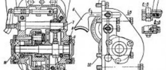
The DT 75 gearbox together with the rear axle are located in one housing. The last element has two planetary mechanisms, multi-stage type. Thanks to this, the equipment experiences minimal stress during operation.
DT 75 gearbox shift diagram: what features does it have?
As standard, the devices are equipped with mechanical types of gearbox. It is usually designed to support 7 stages. A distinctive feature is the presence of a lock on the gear shift mechanism, along with movable gears. Several shafts are mounted on bearings. Blocking devices help avoid rapid wear and tear, which is why they are mounted on equipment.
The DT 75 gearbox diagram assumes the presence of the following main components:
- Gearbox cover.
- A part with a gear that is controlled by other parts.
- The glass with which the rear or front bearing is supplied.
- Screw.
- Retainers.
- Bushings.
- Levers.
- Bearings using a roller mechanism.
- Shafts.
The design cannot do without the main gear. It is designed to increase the moment of force that goes to the drive wheels. In addition, the design is additionally equipped with a set of gaskets - thanks to this, it is not a hassle to perform work such as adjusting the engagement gaps of the main gear.
Be sure to read: Gearbox on the T-150
The housing at the top contains the reverse shaft. The product rotates due to bearings with roller mechanisms. The gears engage when reverse gear is activated.
The quality and wear of the main gearbox mechanisms largely depend on the type of fuel used. Carrying out maintenance on this system also plays a role. In the high-speed box, you need to check from time to time what level the fuel is at. If the quantity is below the established norm, it must be added. The main thing is not to mix liquids from different brands. The manufacturer's catalog will help you make the right choice.
An additional shaft is installed inside the box, along with splines on the surface of which gears are located. The tractor transmission is equipped with a special creeper. This design option is especially relevant for equipment that allows operation using mounted group equipment.
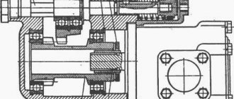
DT-75 gearbox diagram
| № | Name | Catalog number | Quantity per model |
| Transmission | 77.37.001 | 1 | |
| Brake band with linings assembled (for spare parts only) | 77.38-016-1 | 2 | |
| Locking plate | 77.39.153A | 1 | |
| Plug 28, GOST 3111-46 | — | 2 | |
| Wire, GOST 3282-46 | — | 1 | |
| Wire, GOST 3282-46 | — | 2 | |
| Heat-treated segmental key, GOST 8795-58 | — | 1 | |
| 1 | Adjustment shim 0.15 mm | 77.37.111 | 4 |
| 4 | Single row angular contact ball bearing | 700409 | 1 |
| 5 | Washer | 77.37.219A | 1 |
| 6 | Bolt III М12Х25, GOST 7796-62 | — | 6 |
| 8 | Spring thrust ring | 77.32.121A | 3 |
| 9 | Pin | 77.37.132 | 1 |
| 10 | Radial roller bearing with cylindrical rollers | 32213KM | 1 |
| 11 | Bearing cup | 77.37.129-1 | 1 |
| 14 | Glass with seal housing assembly | 77.37.021-1 | 1 |
| 15 | Gear coupling | 77.37.128-1 | 1 |
| 16 | Spring thrust ring | 77.37.180A | 2 |
| 17 | Splined sealing ring | 77.37.127-1 | 1 |
| 20 | Constant mesh drive gear | 77.37.184A | 1 |
| 21 | Ring sealing | 77.37.131 | 1 |
| 22 | Spring thrust ring | 77.37.130A | 1 |
| 23 | Adjustable cotter pin 3.2X18, GOST 397-66 | — | 2 |
| 25 | Transmission cover gasket | 77.37.145 | 1 |
| 26 | Folding plate | 77.37.216 | 1 |
| 28 | Retainer | 77.37.221 | 1 |
| 30 | Locking bolt | 77.37.210 | 1 |
| 32 | Pin | 77.37.115 | 1 |
| 35 | Gearbox cover assembly | 77.37.012 | 1 |
| 36 | Gear shift lever | 77.37.104 | 1 |
| 38 | Bolt М12Х35, GOST 7796-62 | — | 1 |
| 39 | Spring washer 12N, GOST 6402-61 | — | 11 |
| 40 | Lever spring | 77.37.117 | 1 |
| 40 | Plug gasket | 77.37.203 | 1 |
| 41 | Spherical washer | 77.37.118 | 1 |
| 42 | Lever pin | 77.37.116 | 1 |
| 43 | Cap | 77.37.120 | 1 |
| 44 | Case | 77.37.121 | 1 |
| 45 | Pressure ring | 77.37.122 | 1 |
| 46 | Front blocking roller | 77.37.160 | 1 |
| 47 | Sun gear assembly | 77.38.012 | 2 |
| 48 | Retainer | 77.37.163 | 4 |
| 49 | Stopper spring | 54.37.408 | 4 |
| 50 | Transmission cover | 77.37.101 | 1 |
| 53 | Fork 3rd and 4th gears | 77.37.172 | 1 |
| 60 | Bolt М12Х40, GOST 7796-62 | — | 4 |
| 62 | Single row radial ball bearing | 311 | 1 |
| 63 | Primary shaft | 77.37.125-1 | 1 |
| 65 | Lock washer | 77.37.205-1 | 1 |
| 68 | Bearing cup | 77.37.170 | 1 |
| 69 | Spring thrust ring | 77.37.191A | 1 |
| 71 | Radial roller bearing with short cylindrical rollers | 2612KM | 1 |
| 72 | Spring washer 16N, GOST 6402-61 | — | 1 |
| 77 | Gear block of 1st and 4th gears | 77.37.189 | 1 |
| 80 | Lower fork axis | 77.37.142-1 | 1 |
| 82 | Lever axis | 77.37.141 | 2 |
| 83 | Sleeve | 77.37.140A | 2 |
| 85 | Locking bar | 77.37.214 | 2 |
| 86 | Segment key 4Х6.5, GOST 8795-58 | — | 1 |
| 87 | Spring washer 10N, GOST 6402-61 | — | 11 |
| 88 | Bolt М10Х25, GOST 7796-62 | — | 4 |
| 89 | Support bar | 77.37.133 | 2 |
| 90 | Dividing strip | 77.37.135 | 3 |
| 91 | Shift bar for 5th and 6th gears | 77.37.164 | 1 |
| 93 | Side plank | 77.37.134 | 2 |
| 94 | Shift roller | 77.37.144 | 1 |
| 95 | Plug 22, GOST 3111-46 | — | 2 |
| 96 | Ear | 77.37.171-1 | 1 |
| 97 | Bolt М12Х70, GOST 7795-62 | — | 2 |
| 100 | Earring | 77.37.162 | 1 |
| 101 | Bolt М10Х35, GOST 7796-62 | — | 5 |
| 103 | Shift bar for 1st and 2nd gears | 77.37.176 | 1 |
| 105 | Spacer sleeve | 77.37.211 | 4 |
| 107 | Bolt М12Х60, GOST 7795-62 | — | 2 |
| 108 | Fork axis | 77.37.123A | 1 |
| 109 | Locking plate | 77.37.124 | 1 |
| 111 | Bolt М12Х45, GOST 7796-62 | — | 4 |
| 112 | Pin | A38-89 | 2 |
| 113 | Rubber ring | 77.37.155 | 1 |
| 115 | Bolt М20Х80, GOST 7795-62 | — | 2 |
| 116 | Spring washer 20N, GOST 6402-61 | — | 2 |
| 117 | Single row radial ball bearing | 407 | 1 |
| 118 | Additional shaft with bushing assembly | 77.37.022 | 1 |
| 121 | Spring thrust ring | 77.37.209-2 | 2 |
| 123 | Bearing cup | 77.37.108 | 1 |
| 124 | Bearing cup | 77.37.229 | 1 |
| 125 | Radial roller bearing with short cylindrical rollers | 102407 | 1 |
| 127 | Lever lead | 77.37.138 | 1 |
| 130 | Reverse fork | 77.37.136A | 1 |
| 131 | Reverse shift fork assembly | 77.37.015 | 1 |
| 134 | Spring ring | 54.05.436 | 2 |
| 135 | Radial roller bearing with short cylindrical rollers | 32605K | 2 |
| 137 | Fork V and VI gears | 77.37.137 | 2 |
| 142 | Cork | 77.37.202A | 1 |
| 144 | Magnet | 54.38.602 | 1 |
| 147 | Locking bar | 77.37.222-1 | 1 |
| 149 | Bolt М8Х16, GOST 7796-62 | — | 3 |
| 151 | Ring | 77.37.220 | 1 |
Breakdowns and their elimination
Driving over rough terrain requires the use of low speeds. Otherwise, the box fails too quickly, and the box's movement is muffled.
In the following cases, you cannot do without repairing the box:
- The appearance of an oil leak.
- Lever travel is too loose and increased.
- When changing gears, difficulties and certain delays appear.
- The appearance of extraneous sounds. The probable cause is gear wear.
- The noise is coming from the box itself. Especially when moving equipment.
The service life of the box can be reduced both with insufficient oil and with its excess. The oil meter marks will help with timely measurement of the fluid level.
Too much fluid causes the system to overheat and leaks to appear. Usually the latter effect occurs if the sealing materials cease to be elastic.
Changing the fluid assumes a fully warmed-up power plant. Thanks to this, the fluidity of the composition improves. There is a special hole inside for draining. It is closed with a stopper. It needs to be cleaned of various contaminants before being put back into place. Only at the next stage is fresh fuel added. The main thing is to choose a liquid that can maintain its original properties at any temperature range.
Be sure to read: Final drive design
Wear of the internal elements of the gearbox leads to the appearance of various noises. Engine overloads and high loads are the main causes of mechanical damage.
Gearbox diagram
Additional repair recommendations
When disassembling gearboxes, it is recommended to use special stands. Pullers and personal tools become irreplaceable assistants. If possible, the main usable parts should not be disassembled. A complete disassembly is required only if a major overhaul is being carried out.
Here are just some of the main defects that are most often encountered in practice:
- The appearance of cracks and fractures.
- Wear of bearing seats.
- Damage to threaded, smooth holes.
The gearbox housing is discarded when emergency fractures appear that cannot be easily eliminated.
One option for eliminating cracks is to use arc welding. For work, special arc rollers or electrodes are used. Kerosene is a substance that allows you to check the tightness after the work is completed. To do this, weld seams are rubbed using chalk. Only the wall inside the device is wetted with kerosene. If seams appear, some kind of composite insulating material is applied to them. Thanks to this, the transmission of the DT 75 tractor lasts much longer.
When restoring seats, it is also allowed to use different methods:
- Banding.
- Polymer coatings.
- Galvanic coatings.
There are other options, but they deserve separate consideration.
Taking into account additional nuances
If the input shaft or axle is bent, then they are processed using a special press, in a cold state. With a few extra efforts, owners will increase the accuracy of their work.
Seats for bearings and shafts also require the use of several techniques:
- Arc surfacing.
- When metal strips are boiled.
- Ironing.
- Application of polymer-based materials.
During restoration, many parts require first heating to a certain temperature, and then cooling. Pressing helps to achieve certain sizes of holes and parts themselves, when necessary.
Tractor diagram DT 75
Even inside the gears, only a part can be replaced if it has the most serious wear, while the remaining indicators remain within normal limits. They simply remove the part with the most wear, since it would be impractical to get rid of the entire structure. The new ring gear is made using the same steel as the original part. After this the connection is made.
Be sure to read: Oil for walk-behind tractor
Shift levers and forks are more likely to bend, suffer from cracks, break, and wear out. Emergency breakdowns lead to the need to get rid of the entire part.
Equipment and release
The tractor is equipped with an agricultural type rear linkage. Has a power take-off shaft. Can be aggregated with a mounted plow, mounted harrow, seeder, potato digger. Can be equipped with bulldozer equipment. Towing a trailer.
The tractor has been produced by the Volgograd Tractor Plant since 1963, or more precisely, since December 30, 1963 (according to other sources, since 1962), the Pavlodar Tractor Plant was produced en masse from 1968 to 1992, in relatively small quantities in the 90s years. The number of tractors produced at VgTZ from 1962 to 1995 is 1,652,500 units, at PTZ from 1968 to 1995 - 862,300 units. The first two experimental DT-75s were assembled at VgTZ on July 16, 1956. In May 1960, a decision was made to reconstruct the plant and switch to production of the DT-75 tractor. On August 28, 1967, serial production of the DT-75M tractor began at VgTZ; in 1969, production of the DT-75B swamp tractor began (according to other sources, in 1968). At PTZ the first tractor was produced on August 12, 1968 (DT-75M). The difference between the tractors of the Pavlodar Tractor Plant and the tractors of the Volgograd Tractor Plant is the presence of the inscription “Kazakhstan” instead of “DT-75” on the sides of the hood, color (blue with a matte white cab top for DT-75M, yellow for DT-75ML, DT-75T versus the usually red color for VgTZ tractors). Tractors with a fuel tank located to the left of the cab (for example, DT-75V, DT-75MV, DT-75N) were produced only at VgTZ. Yellow tractors with a large cab (DT-75ML, DT-75T) were produced only at PTZ.
A little about safety
The main thing is to ensure that all working mechanisms are in good condition. This is especially true for the gearbox itself and the braking system. Any turns or parts with rough terrain should be negotiated only at low speeds. The occurrence of a malfunction causes the tractor to stop until the defect is completely eliminated. Overcoming water obstacles is not recommended. If this is necessary, the movement begins only after careful preparation.
Possible faults
All about the T 40 tractor gearbox
Most often, malfunctions in the chassis and gearbox occur due to improper operation, as well as untimely maintenance. Otherwise, the DT 75 transmission is very reliable, its service life is comparable to that of the engine. Gearbox failure is accompanied by the following symptoms:
- increased noise while driving;
- metallic knock (wear of bushings or gear pairs);
- difficulty shifting or inability to engage the desired gear;
- long travel of the gearshift knob;
- oil leaking from under the cap.
The most common cause of gearbox failure on DT 75 is a critical drop in the oil level inside. This leads to overheating and accelerated wear in areas of friction of gears and roller bearings on the shafts. The oil level is checked regularly through special eyes in the housing. Despite the fact that the design of the gearbox includes special cups near the seals that prevent leakage, oil can be wasted or seep through other seals.
The wear of metal parts inside the box itself has its own patterns. First of all, the gears of the first and second gears, the support bearings of the input shaft, and the gear shift forks fail. The splined joints on the shafts are also subject to wear. A large gap in working components leads to an increase in the load on the part and contributes to rapid breakdown.
Troubleshooting gearboxes
Repair of the DT 75 gearbox should be carried out in a workshop or special service. To remove and disassemble the gearbox, you will need lifting equipment, special pullers and tools. During the troubleshooting process, components are discovered that require replacement, and parts or seats that can be restored. The design of the DT 75 tractor allows the following operations to be carried out during repairs:
- banding;
- galvanic and polymer coatings;
- welding;
- arc surfacing;
- forging and pressing.
For example, gear wheels are made dismountable, so during the repair process the ring gear is replaced separately from the supporting part. This saves money and simplifies all repairs. Bent shafts can be straightened in a press followed by annealing in an oven, etc.
DIY turn relay
Sometimes situations arise when the standard turn signal relay fails and it is not possible to purchase a new device. In such a situation, you can try to make a turn signal relay with your own hands to provide the car with the necessary signals. The simplest electronic devices that you can create yourself are simple and easy to use, operate smoothly and reliably. High accuracy is achieved through the use of PWM controllers used in all circuits.
The simplest replacement for an electromagnetic relay is designed for a maximum load power of 150 W. It is connected to the positive terminal. If the IRFZ44 field switch is replaced with the IRF3205 model, then 200 W can be connected. This simple circuit ensures high accuracy of operation. The blinking frequency does not depend on the power of the light bulbs, so LED, halogen and other lamps can be included in the circuit.
The frequency of flashing is directly related to the capacitance of the capacitor. As the capacity increases, the light bulb will blink more rarely, and, conversely, decreasing the capacity will lead to faster blinking. The low-power 1n4148 diode can be replaced by any similar element. When the circuit reaches a power of 80 W, a slight generation of heat is observed in the field-effect transistor area. This means it is ready to use.
There is another simple circuit of a turn relay with a coil - simple, reliable and inexpensive. It is capable of lighting both regular light bulbs and LED ones and is designed for 12 V. The contacts are connected according to the principle of a regular switch, that is, in series with the light bulb. The LED is installed in the circuit as an indicator during commissioning work. The device parameters are adjusted by changing the resistance of the resistor.
Circuit breakers
Electrical fuses are designed to protect against overloads and short circuits in electrical circuits.
Molded Panel Instrument Fuses
Three fuse blocks for electrical circuits are mounted in the instrument panel with a molded panel. To access the fuses located in the instrument panel of the Belarus MTZ-82.1, 80.1, 82.2 tractor, you need to unscrew screw 2 and fold back panel 3.
Rice. 1 – Access to fuses located in the instrument panel with molded panel
1 – instrument panel; 2 – screw; 3 – panel.
Rice. 2 – Fuses located in the instrument panel with molded panel
Purpose of instrument panel fuses with molded panel
1 – 15A – Brake lights, terminal (6) and terminal (8) of the trailer socket. 2 – 15A – Road train sign lights (if equipped), rear work lights, cabin lighting. 3 – 15A – Hazard warning lights. 4 – 25A – Front and rear windshield wipers, front window washer. 5 – 15A – Sound signal. 6 – 25A – Main beam of road headlights, signal lamp for turning on the main beam of headlights. 7 – 25A – Front working lights, signal beacon (when installed). 8 – 25A – Power supply for the heater fan control circuit or power supply for the heater fan 80-8101720. 9 – 25A – Power supply to consumers operating when the starter switch and devices are in the “devices on” position: devices, speed sensors, power to fuse 15 and 16. 10 – 25A – Power supply to the electric motor of the fan-heater (when installing the fan-heater 80- 8101720 this fuse is not used); 11 – 7.5A – Left side parking lights, trailer socket terminal (7), license plate lighting. 12 – 15A – Side lights on the starboard side, terminal (5) of the trailer socket, instrument lighting. 13 – 7.5A – Low beam of the left road headlight. 14 – 7.5A – Low beam of the right road headlight. 15 – 7.5A – Power supply for instruments, speed sensors, warning lamp units, emergency sound alarm (buzzer) and parking brake relay-breaker. 16 – 15A – Turn signal relay, glow plug block, glow plug relay coils.
Modifications
Model DT-75M. Produced since 1967 at VgTZ and since 1968 at PTZ. Differed from the base model:
- using the A-41 engine (90 hp);
- higher cabin, offset to the right;
- increased capacity fuel tank (315 l), located on the left side of the cabin.
Photo of the DT-75M tractor
Model DT-75B. Swamp modification, designed for agricultural work in peat mining and drained swamps. It has been mass-produced since 1968 at VgTZ. Main differences:
- engine SMD-14NG (80 hp; 1800 rpm);
- cabin similar to DT-75M;
- the side members on the welded frame are connected by elongated beams, as a result of which the width of the tractor increased to 2240 mm and the track to 1570 mm;
- the width of the tracks was increased to 670 mm, which made it possible to achieve a specific ground pressure of 0.24 kgf/cm2 with the guide wheels lowered (longitudinal base - 2365 mm) or 0.33 kgf/cm2 with the guide wheels raised (longitudinal base - 1612 mm);
- Front and rear pans have been added to the design to protect the engine and transmission;
- instead of the RCM, a 4-stage creeper is used.
Model DT-75K is designed for agricultural work on mountain slopes with a steepness of no more than 20° at an altitude of up to 2000 m above sea level. Manufacturer: VgTZ (since 1972). This modification was equipped with an SMD-14NG engine and had the following features:
- welded frame and tracks are identical to the DT-75B model;
- a support safety device was used to prevent overturning on slopes;
- the cabin had a visual roll indicator and was equipped with two seats located one opposite the other;
- A reverse gearbox in combination with front and rear linkage mechanisms made it possible to perform work using the shuttle method.
The next modification, DT-75N, was produced with an upgraded SMD-18N engine. This unit was equipped with a turbocharger and fuel pump adjustment, due to which the power of the power plant was 95 hp. (1800 rpm). The tractor was produced only at VgTZ and was mounted with the same mounted mechanisms as the DT-75M.
Photo of the DT-75N tractor
Model DT-75S. Designed for agricultural, loading and earth-moving work. Key Features:
- V-shaped six-cylinder diesel engine SMD-66 (170 hp, 1900 rpm) with gas turbine supercharging;
- 2-speed PTO;
- a torque converter that provides automatic control of the tractor speed depending on the resistance value;
- The fuel tank (360 l) and the hydraulic oil tank are installed on the left side of the cab.
The DT-75D model with A-41 or D-440-22 engines boasts improved fuel efficiency, increased reliability of the transmission, chassis system and rear linkage. The traction qualities of the tractor are increased by installing a reverse gearbox or speed reducer. For aggregation, the DT-75D uses: a hydraulic control and drive system, a towing device, a rear linkage, a power take-off shaft and removable front ballast weights.
The DT-75ML model has been produced since 1986 only at PTZ. The main differences: the lining of the engine compartment has been changed, the cabin has been increased (height - 2923 mm) and the number of control instruments has been increased.
Photo of the DT-75ML tractor
Since 1991, PTZ has manufactured wheeled modifications of the tractor - DT-75MLK, DT-75KP, DT-75DK and DT-75KPM. Wheeled versions were produced in small series and were used for light reclamation, road, construction and agricultural work.
Among the less common models we will mention the DT-75V (SMD-14NG engine), DT-75RM (RM-80 or RM-120 engines), DT-75DM (D-245.25 engine) and DT-75MV (A-41 engine), produced only at VgTZ. The DT-75 was further developed in a new VTK product under the trade name “AGROMASH 90TG” with an A-41SI-02 engine (94 hp, 1750 rpm), which has been produced since 2009.
The new crawler tractor has a new design and, like its predecessor, is distinguished by enviable versatility. It can perform the entire range of agricultural operations, as well as road-digging, land reclamation, construction and loading work.
Tractor engine
Chassis of the VAZ The 90-horsepower A-41I diesel engine was used for the first time as a power unit in the tractor. Subsequently, agricultural machines also began to be equipped with D-245.552 units, which are equipped with various modifications of trucks and special equipment. There are differences between these units:
- A-41I produces 94 l/s at 69 kW;
- D-245 – 95.2 l/s at 70 kW.
The engines are in-line, the tractor crankshaft rotates at 1750 rpm for the A-41I, at 1800 rpm for the D-245.
Tractor engines are powered by diesel fuel: a fuel tank with a capacity expanded to 315 liters is mounted on board the tractor, meeting the power needs of the powerful power unit.
The volume of the A-41I is an impressive 7.43 liters. The newer four-stroke diesel D-245 is less “voluminous”, only 4.75 liters, which gives the tractor visible savings on expensive diesel fuel.
conclusions
I would like to be objective and not sing praises of domestic technology. BUT the fact that the DT 75 bulldozer has been successfully working in many areas since 1984 speaks in its favor. The technical content cannot be compared with the capabilities of foreign equipment, but as experts and the category that had the opportunity to drive the DT 75 (photo of transporting tractors on the left) note, they claim that the tractor is not inferior in performance to many foreign models. The DT 75 tractor is cheaper than its foreign competitors, the tractor is unpretentious in repair, and replacing parts is cheaper than imported equipment.
Even minor repairs can be carried out in the field. But the equipment needs care
Therefore, carrying out preventive work and especially preparing equipment for spring field work should be carried out with special attention. Great importance must be paid to attachments, analyze the causes of failure of a particular unit or component
Monitor the hydraulic system and prevent equipment downtime during the busy season of sowing and cultivating the land.
Cabin
We remove the gearbox on a 16 valve VAZ-2112 with our own hands
The first samples of the DT-75 could hardly boast of the comfort and technical equipment of the cabin. Later, in the DT-75M it became more convenient, like a car. The viewing angle has increased significantly by shifting the frame axis to the right. Front and rear windshield wipers guarantee good visibility and can even remove ice. A glass washer is also installed.
Cabin interior DT-75M
The new sprung cabin has become noticeably higher. Consumers became so accustomed to the old design that they began to write complaints to the plant, because after modernization the equipment no longer passed under trees. As a result, the original performance was restored.
The DT-75M crawler tractor is designed to operate in harsh weather conditions. Therefore, heating equipment is installed in the cabin for heating. For driver comfort, the cabin is equipped with a ventilation system that cleans the air from dust. Additionally, it is cooled and humidified. Switching on occurs automatically after closing the door and window openings. To maintain a microclimate, the cabin is insulated from noise and dust.
Reverse device
Structurally, the reverse gearbox contains not only toothed bevel gears that allow you to change the angular speed of the gearbox drive shaft, but also a reverse mechanism that determines the direction of rotation.
The drive gear, connected to the shaft coming from the clutch, is in mesh with a pair of driven gears mounted on the shaft of the tractor's manual transmission. The direction in which rotation occurs is controlled by a clutch installed between the gears and providing connection to one of them. This fairly simple design shows high efficiency and reliability. In the absence of mechanical breakdowns, this mechanism will work in any conditions, flawlessly performing its assigned function.
Control is carried out using a special reverse lever. Next to it are the necessary tips designed to help avoid doubts and mistakes. There is nothing complicated about this - it is much more difficult and important to understand why which gear is needed and choose it correctly. Errors in this matter can lead to ineffective operation of tractor equipment or even the inability to perform work.