KranStal LLC specializes in the design, installation, and production of crane tracks (crane tracks) and trestles for them. We solve problems of any level of complexity - design, inspection, installation, repair of overhead and ground crane tracks in the case of installation of new lifting and transport equipment on an unequipped production site or building, refurbishment of an existing production site, as well as if existing equipment is transferred to another production site . Our specialists go to the site of the intended installation of the PTM and carry out a range of works aimed at improving and increasing productivity.
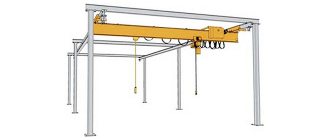
Load patterns and composition of crane structures.
1 – crane beam; 2 – brake structure; 3 – connections; 4 – rail with fastenings
The rail support track of an overhead crane consists of main and auxiliary elements. The main elements of the track are rails and crane beams. Auxiliary elements include the under-rail bed, parts for fastening rails to crane beams and beams to columns, as well as end stops and switching rulers.
For the movement of load-lifting cranes and their cargo trolleys equipped with running wheels with a cylindrical rim, steel rails with convex and flat heads are used, and for wheels with a conical rim - only with convex heads. As rails with convex heads, broad gauge railway rails of type P and special crane rails of type KR according to GOST 4121 - 76 are used, and with flat heads - rolled steel bars of square or rectangular profile. Steel crane rails of the KR type have a wider base (supporting part), due to which the load from the crane running wheels is distributed more evenly over the upper belt of the crane beam. In addition, they absorb horizontal lateral loads well and are more suitable for the operating conditions of load-lifting cranes. Therefore, for cranes of the 6K-8K operating mode group, only KR type rails are used. An example of a symbol for a KR type rail with a nominal head width of 100 mm: Rail KR100 GOST 4121 - 76. Recommendations for the selection of crane rails depending on the crane’s lifting capacity and the load on the running wheel.
2.3. Length of crane tracks.
Based on the found extreme crane stops, the length of the crane runways is determined (Fig. 2.2.):
L
PP = l KR + B + 2·l BRAKE + 2·l TUP ,
where L
PP
is the length of the crane runways, m;
l KR -
the distance between the extreme crane stands, determined according to Fig. 2.1., m;
B
- crane base, determined from reference books (Appendix A), m;
l BRAKE
- the magnitude of the braking distance of the crane, taken to be at least 1.5 m;
l TUP
- the distance from the end of the rail to the dead ends, equal to 0.5 m.
The determined length of the crane runways is adjusted upward, taking into account the multiple length of the half-link, i.e. 6.25 m. The minimum permissible length of the crane runways is two links (25 m).
Designations:
L – crane track span – distance (in plan) between the axes of the rails Lе – overpass span – distance (in plan) between the axes of the overpass columns (across the rails) Lz – span of the building, workshop – distance (in plan) between the axes of the columns of the building, workshop (across the rails) W - column spacing - distance (in plan) between the axes of the columns (along the rails) U.G.R. – rail head level – distance (in height) between the floor, ground, zero level and rolling surface of the crane rail U.S.K. – level of the building structure – the distance (in height) between the floor, the ground, the zero level and the lowest point of the truss, beam.
Construction of the subgrade
Naturally, our crane cannot stand haphazardly. Installation takes place on a fairly level area.
First, let's decide on the dimensions. The minimum length of the subgrade is defined as twice the length of the rail plus the slope. As you remember from previous articles, we use KR-70 and above with a length of 12.5 meters. Therefore, the minimum length will be 25 meters.
The maximum is limited by your imagination. The main thing is to be able to deliver the cargo to any necessary place on the work site.
Let's move on to more detailed work. The slope must be minimized. Longitudinal is only possible up to 0.003. The transverse slope should be the opposite. Limits: 0.008-0.01. Moreover, the direction should be in the opposite direction from the boom of a working tower crane. This is due to the calculation of the stability of the tower crane in operation. This slope will reduce the risk of capsizing.
It would seem that's it. But this is where the nuances begin.
Your roadbed will obviously pass over some underground communications, and God forbid it will be just a subway at great depth. Sometimes you come across hastily laid pipes. In this case, you or those who are responsible for the construction of the crane tracks need to carry out calculations for compression and, if necessary, install additional ceilings.
From the moment work begins on the roadbed, it is necessary to monitor its safety. Do not allow debris or vehicles to enter the finished canvas.
And don't forget about drainage ditches. The accumulation of liquid in the soil leads to its softening and significantly reduces its ability to resist load.
After completing the construction of the subgrade, it is worth checking the density of the soil again and you can proceed to the next stage.
Designations:
L – crane track span – distance (in plan) between the axes of the rails Lе – overpass span – distance (in plan) between the axes of the overpass columns (across the rails) Lz – span of the building, workshop – distance (in plan) between the axes of the columns of the building, workshop (across the rails) Ш – column spacing – distance (in plan) between the axes of the columns (along the rails) U.G.R. – rail head level – distance (in height) between the floor, ground, zero level and rolling surface of the crane rail U.S.K. – level of the building structure – the distance (in height) between the floor, the ground, the zero level and the lowest point of the truss, beam.
Construction of ground crane tracks for gantry cranes
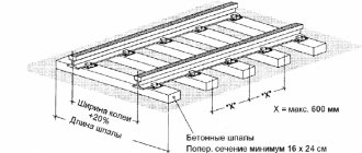
Crane tracks conventionally consist of a lower and upper structure.
The lower one involves the creation of a special soil bed and the organization of a drainage system. Upper - installation of sleepers, rails and joints. The upper one also includes a ballast prism in the form of sand or crushed stone. Sand ballast - for cranes with a lifting capacity of 5 tons (with a layer thickness of more than 300 mm). Crushed stone-gravel prism for cranes with such tonnage can have a slightly smaller thickness - from 250 mm. For cranes with greater lifting force, the ballast prism should be 400 mm or more. The ends of the sleepers must be overlapped by such an embankment by at least 200 mm.
For crane tracks of gantry and semi-gantry cranes located on the ground type, the installation rules of GOST R 51248-99 are provided. It provides requirements for installation teams that are certified for this type of activity. To get started, you should create a project that includes:
- passport and design of the crane runway (including its arrangement);
- a copy of the general construction plan;
- documentation on the availability of crossings for ground transport through crane tracks.
It also includes data on the track width, the length of the crane tracks, and places for parking the crane.
Preliminary geodetic preparation is carried out with an assessment of the nature of the soil and the location of future crane tracks. Surveyors will calculate possible soil subsidence and help adjust the parameters of crane tracks.
On a note!
Mobile jib cranes can also be mounted on crane tracks. This depends on the specifics of the tasks of individual production. The installation principles and design of crane tracks for jib cranes are similar to those shown above for ground-based cranes.
Designations:
L – crane track span – distance (in plan) between the axes of the rails Lе – overpass span – distance (in plan) between the axes of the overpass columns (across the rails) Lz – span of the building, workshop – distance (in plan) between the axes of the columns of the building, workshop (across the rails) Ш – column spacing – distance (in plan) between the axes of the columns (along the rails) U.G.R. – level of the rail head – distance (in height) between the floor, ground, zero level and rolling surface of the crane rail U.S.K. – level of the building structure – distance (in height) between the floor, ground, zero level and the lowest point of the truss , beams.
Execution principle
There are two structurally different options for installing guides and orienting them in space. Let's look at each of them.
Support
The wheels of the equipment are located on top of the rail track, and the pressure from the load is transferred from the rolled metal products to the overpasses (if any) or to the beam spans.
- Advantage: excellent for those cases where you have to work with heavy objects, as it has the highest lifting capacity possible today - up to 500 tons.
- Disadvantage: expensive to implement, especially on large sites - its arrangement requires relatively serious financial expenses.
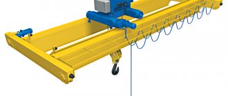
Suspension
In this situation, the bridge with the trolley and all the tools “on board” is attached to the lower shelves of the canvas, and the rails, in turn, are fixedly fixed on the ceilings or walls.
Pros: simplicity and speed of installation, relative cheapness of organization, wide working area, the ability to install only in part of a workshop or other production premises, free choice of the number of spans, a variety of options for docking and moving trolleys.
Disadvantages: relatively small lifting weight limit - up to 8, maximum up to 10 tons, which somewhat limits the scope and cases of application.
Designations:
L – crane track span – distance (in plan) between the axes of the rails Lе – overpass span – distance (in plan) between the axes of the overpass columns (across the rails) Lz – span of the building, workshop – distance (in plan) between the axes of the columns of the building, workshop (across the rails) Ш – column spacing – distance (in plan) between the axes of the columns (along the rails) U.G.R. – rail head level – distance (in height) between the floor, ground, zero level and rolling surface of the crane rail U.S.K. – level of the building structure – the distance (in height) between the floor, the ground, the zero level and the lowest point of the truss, beam.
Rail installation methods
For modern bridge systems, installation of crane tracks is carried out in the following ways:
- Pressure plates.
- By welding.
- Fixation with threaded hooks.
The main requirement for each of the listed methods is to ensure strength and reliability. To ensure this requirement, the following are used as fastening elements:
- clamping pads;
- staples (welded or spring);
- spring bars;
- hooks with adjustable nuts.
All types of fastenings are divided into two categories: solid-monolithic and prefabricated. The first type represents a one-piece structure. It is connected using powerful rivets or welding.
The second type is most widely used. It provides the ability to carry out horizontal straightening of the track. This design has better maintainability. It is considered more practical. To ensure timely and reliable stopping, brake buffers are installed at the extreme points of the bridge track.
The contact buffer absorbs kinetic energy through mechanical shock. The unstressed one is made in the shape of a cone. It works on the principle of rolling onto a buffer. The third type is called mixed. It combines the advantages of the previous two.
Ensuring high quality installation guarantees rigid fastening of the entire crane system. During the entire period of operation, it is necessary to periodically check the condition of the bridge system and the quality of grounding.
Service
To ensure safe operation of the overhead crane, it is necessary to carry out regular maintenance of the crane runways, if necessary, to carry out their repair. The list of maintenance includes the following activities:
- monthly scheduled inspection;
- periodic maintenance, in accordance with the operating instructions for a specific type of overhead crane;
- seasonal maintenance (when operating the mechanism outdoors).
In addition to the listed types of inspection, a daily comprehensive inspection is provided before starting work on the crane installation. During such an inspection, defects in the rails themselves, fastening elements and grounding quality are identified. The inspection results are recorded in a special journal. In the event of malfunctions affecting the safety of operation of the overhead crane, work on it is stopped until the necessary repairs are carried out.