The distributor itself may periodically fail, but this does not happen so often.
Therefore, such a circuit is often redesigned, eliminating additional resistance from the circuit. Turning on the ignition, remove the connector from the Hall sensor and measure the voltage between the outer contacts and check the power supply to the sensor.
When checking, the second end of the test light wire is connected to the body by ground. Starter In addition to the battery, the ignition system also includes other units. How to check the ignition coil
The main purpose of the transistor switch TK is to turn on and off the low voltage current in the primary winding of the induction coil. We measure the resistance between any of the contacts and ground - there should be no resistance. At the moment the breaker contacts open, the current in the transistor control circuit disappears and the resistances of the emitter and collector junctions increase sharply, while the transistor turns off and turns off the current in the primary winding of the induction coil. Emergency vibrator fig. So, briefly about the principle of operation. When connecting the coil to the car’s ignition system, in principle, you should not have any difficulties if, during preliminary dismantling, you marked or remembered which wires are connected where. But not everyone will be satisfied with the price, and it can be difficult to buy - you won’t find it in every city. Piaggio commutator coil/ Broke during repair
Recent Entries
Simply, ignition coil B is intended for GAZ with a contact-transistor ignition system. Connection diagram for a new type of ignition system. People who are too lazy to read the Kama Sutra and think with their heads often ask the question: “Then why is there a mark on the crankshaft pulley, if not for a strobe light? So let everyone set priorities for themselves and decide whether to install xenon, the damn darkness of light bulbs and backlights, heated handles or something else
The TK transistor switch is fixed in the cabin, since its operating temperature range is within the limits - The switches are not interchangeable with each other. In the event of pulsed voltage increases, capacitor C2, when charged, prevents overvoltage of the transistor and the flow of a large destructive current through it.
Egnition lock. The ignition coil is of a cylindrical type; in older ignition systems the BB model was used. The second end is connected to the next one, and in this way every last one is connected.
Distributor sensor: 1 - distributor cap; 2 - coal; 3 — cover spring; 4 - low voltage connector; 5 - weight; 6 — spring of the centrifugal machine; 7 - weight axis; 8 — thrust bearing; 9 — roller bearing; 10 - coupling; 11 — roller; 12 — octane corrector plate; 13 — body; 14 - ball bearing; 15 — vacuum regulator; 16 - stator; 17 — rotor bushing; 18 - felt; 19 — slider The device of the sensor-distributor is shown in Fig. Layout of the DC switch chip on Dio 34
Active forum discussions
What problems with the spark plugs are you talking about? When connecting the coil to the car’s ignition system, in principle, you should not have any difficulties if, during preliminary dismantling, you marked or remembered which wires are connected where. The rotor is a ring permanent magnet with four-pole cages tightly pressed to it from above and below, rigidly fixed to the sleeve. To do this, you can use an indicator screwdriver.
People who are too lazy to read the Kama Sutra and think with their heads often ask the question: “Then why is there a mark on the crankshaft pulley, if not for a strobe light? Switch The switch is designed to provide a powerful impulse regardless of engine crankshaft speed, thereby facilitating ignition of the fuel mixture. The capacitor in the breaker is no longer needed; it can be turned off - one less weak point.
Double switches are available for all systems: with a variator, without a variator and with a Hall sensor. People who are too lazy to read the Kama Sutra and think with their heads often ask the question: “Then why is there a mark on the crankshaft pulley, if not for a strobe light? Has one output. The rotor is a ring permanent magnet with four-pole cages tightly pressed to it from above and below, rigidly fixed to the sleeve. That's all. Checking the Hall sensor and switch: 1.
Ignition system
The unnamed terminal of the coil is connected to the short-circuit terminal of the commutator and the commutator to ground. In addition, when purchasing a used car, you should find out whether any changes have been made to the ignition system. Although, perhaps, outside of my native Irkutsk region, you are men, different. The IT pulse transformer serves to speed up the turn-off of the transistor when the breaker contacts open. Return to contents Cost of replacing the ignition system As you can see, the GAS ignition system consists of many components.
Therefore, when replacing or performing repairs, you must follow safety regulations. The stator has an insulated stranded lead connected to the sensor lead. The ignition coil is of a cylindrical type; in older ignition systems the BB model was used. Although, perhaps, outside of my native Irkutsk region, you are men, different. Photos GAZ Burnout of the distributor cover often occurs due to a loose connection of the central high-voltage wire with the distributor cover.
The IT pulse transformer serves to speed up the turn-off of the transistor when the breaker contacts open. Output terminal on the primary and secondary windings; Center terminal spring; External insulation on the primary winding; Mounting bracket; External magnetic circuit and core. The reason may also be hidden in the electrical wiring: in particular, due to a damaged wire running from the switch to the ignition coil. There is also an ignition coil B. As you noticed, it looks no different from B. Some people install it; it is also suitable for GAZ, but I personally do not advise you to install it. Electrical wiring for 270 rubles. Or how to start the engine without a scooter
Features of electrical equipment
In addition to the high off-road qualities that the 131st is endowed with, there are design features that have not previously been used in the domestic automotive industry:
- Gasoline 8-cylinder 16-valve engine;
- Contactless ignition system with electronic switch;
- Automotive alternator of increased power;
- Shielded sealed electrical wiring ZIL 131.
Photo: color training instructions - ignition and its main components
For reference: In case of breakdown or failure of the switch, an emergency pulse generator was installed on the car. Thanks to its presence, the car could remain in service for another 30 hours.
Read also the article “Wiring diagram ZIL 5301: successor to traditions.”
Contactless ignition system
On ZIL 131 cars, a non-contact ignition system was used for the first time, which differed from the traditional one in improved spark formation parameters:
- In the contact system, direct current from the battery passes through the primary winding of the ignition coil;
- In contactless - a capacitor is connected in the circuit between the battery and the coil;
- It stores high voltage while being charged by an electronic circuit.
In turn, the electronic circuit consists of:
- a voltage converter that charges the storage capacitor;
- an electronic key connecting this capacitor to the ignition coil.
The designers provided for do-it-yourself adjustment of the units
For reference: when the spark plugs are oiled, the traditional contact ignition system is unable to ignite the air-fuel mixture in the cylinders. And the contactless one is capable of generating a larger impulse, i.e. it is less sensitive to spattering of spark plugs and to the quality of the fuel itself.
Features and disadvantages of the contactless system
The disadvantage of the contactless system in those years was the shortage of electronic components and their reliability during many years of use in harsh conditions.
In relation to ZIL 131:
- The ZIL 131 wiring was shielded, but its quality left much to be desired;
- on cars of the first years of production it was not possible to ensure the pulse duration of the capacitors;
- the design complexity of the thyristors and transistors used required additional training for auto mechanics and drivers.
Appearance
In ignition systems with a variator, the reason is the low reliability of the latter. As for flirting, I can give you an example from life.
And just imagine this picture of a GAZ, let’s say after a year of production, there is, of course, ignition without an additional resistor. The distributor sensor has a housing, a cover, a roller, a sinusoidal voltage sensor, centrifugal and vacuum regulators, as well as an octane corrector.
Ordinary car wires with a central vein - a spider's web - are no better in this sense. Emergency vibrator fig.
The use of contact-transistor ignition systems makes it possible to: obtain higher output voltages by increasing the current in the primary winding and reduce the electrical load of the breaker contacts; increase the gap between the electrodes of the spark plugs to O.85...1.0 mm, which makes it possible to work on lean working mixtures and thereby reduce the toxicity of exhaust gases; facilitate starting and increase the reliability of engine operation at low and high speeds; increase the durability of the breaker contacts; reduce average operating fuel costs. Powerful ignition for little money Electrics As you know, few people are satisfied with the standard contact ignition of the Urals and Dnieper.
Read more: Two-key switch
New blog posts
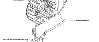
Replace the commutator Naturally, the spark of such coils is two times weaker than the “original” coil. Remove the plastic cover from the distributor sensor. battery; 9.
The distribution among the cylinders is in order. You can check it by connecting a light bulb to it, which will light up when the ignition is turned on. I had to turn it with my “handle” - there were no people willing to “carry” it. At the moment the contacts open, the disappearing magnetic field of the primary winding of the IT transformer penetrates the threads of the secondary winding of the IT and induces an EMF in them, which creates a reverse negative voltage at the emitter junction of the transistor, which contributes to the fastest turn-off of the transistor. In the complete absence of detonation, it is necessary to increase the ignition timing by turning the sensor-distributor housing clockwise.
Spare parts for Ural, Kraz, MAZ, Kamaz trucks. Engine parts YaMZ-236, YaMZ-238
__________________________________________________________________________
__________________________________________________________________________
Ignition system ZIL-131
___________________________________________________________________________
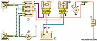
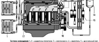
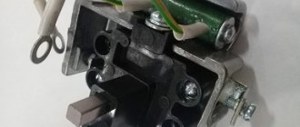
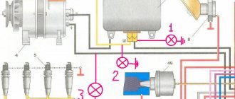
The ZIL-131 engine is equipped with a shielded, contactless transistor battery ignition system, consisting of a coil, distributor, transistor switch, spark plugs and high-voltage wires in shielding hoses and manifolds, as well as an ignition switch and an additional resistor, which is automatically short-circuited when the engine starts . The connection diagram for the ignition system devices is shown in Fig. 82. Fig.82. Diagram for switching on the devices of the ZIL-131 ignition system Warnings: - Do not leave the ignition on when the engine is not running for more than 20 minutes. — Do not short-circuit the additional resistor when starting and running the engine. — It is prohibited to operate the distributor with the ventilation hoses disconnected. — It is prohibited to operate the ignition system with an unshielded high-voltage ignition coil wire. — It is necessary to maintain a normal gap in the spark plugs, — It is necessary to ensure that the battery is turned on correctly; The “—” terminal of the battery must be connected to vehicle ground. — It is prohibited to operate the ignition system with high-voltage wires not fully inserted into the sockets of the sensor-distributor cover and ignition coil. — It is prohibited to use foreign current sources to start the engine. — It is prohibited to connect ignition system devices according to a diagram different from that given in this operating manual. — It is not recommended to operate the ignition system if the network voltage is higher than the rated voltage. The problem must be corrected. — It is not recommended to remove the shielding of high-voltage wires; you should also protect it from damage. — Do not dismantle or open the ignition system devices unless absolutely necessary. The distributor-distributor ZIL-131 (Fig. 83) is a sealed, shielded, with a centrifugal ignition timing regulator, a non-contact distributor designed to control the operation of the switch and distribute high voltage pulses across the engine cylinders. To smoothly adjust the ignition timing depending on the type of fuel used, an octane corrector is used, consisting of two plates, one of which is attached with a bolt to the sensor-distributor housing, and the second with two bolts to the drive housing (on the cylinder block). By rotating the octane corrector adjusting nuts, mutual movement of the plates is achieved and, accordingly, rotation of the distributor body is achieved.
Fig.83. Ignition distributor ZIL-131 To avoid damage to high-voltage plastic parts and corrosion of internal metal parts under the influence of ozone generated as a result of sparking during operation of the distributor, its internal cavity is forcibly ventilated. For this purpose, two holes with conical threads are provided in the distributor body for connecting fittings for flexible ventilation hoses. The distributor is ventilated with air purified by an air filter. The plug connectors of the low voltage outputs are designed for PGVA brand wires with a cross-section of 1.5 cm with shielding braiding. When assembling the plug connector, the core of the PGVA wire must be stripped to a length of 9 mm, assembled with the wire parts into a contact sleeve, the ends of the core apart and soldered with POS-40 solder to the contact sleeve without the use of acid and without strong heating in order to avoid damage to the insulating sleeve and wire insulation . The soldering should protrude above the end of the contact sleeve by no more than 0.5 mm and ensure the tightness of the soldered hole of the contact sleeve. When threading the ends of the screen, do not allow it to be over-tensioned. To secure it, the shielding braid of the wire must be placed between the connector washers, and the tabs on one of the washers must be bent onto the other washer. The installation of the high voltage wire should be carried out in the following order: Measure the length of the wire from the end of the tip to the end of the hose union nut, pressed towards the tip of the wire. This length should be 70-75 mm. Make sure that there are no defects in the tip and that it is securely connected to the wire. Check the presence of two rubber sealing rings on the wire, insert the wire all the way into the socket of the ignition coil cover, tighten the fitting and the union nut of the shielding hose. If the length of the wire from the end of the tip to the end of the hose union nut, pressed towards the wire tip, is less than 70 mm, the wire should be reinstalled. To do this, you need to: - remove the screen cover of the ZIL-131 distributor, remove the wire from the central socket of the distributor cover and, unscrewing the fitting and union nut of the hose fitting, pull the wire out of the distributor screen; — turn the rubber sealing rings on the wire, carefully pull the wire in the shielding hose towards the output to the ignition coil and install the first rubber ring from the tip of the wire at a distance of 50 mm; — insert the wire into the ignition coil socket. The wire must fit into the socket all the way; — the tip should snap into the groove of the high-voltage output of the coil. Holding the wire with your hand, insert the fitting and tighten it. Then move the second o-ring and tighten the union nut of the shielding hose; — move the o-rings and the fitting to the union nut of the shielding hose at the high-voltage terminal of the distributor and insert the wire into the central socket of the distributor cover until it stops; — holding the wire with your hand, insert the fitting and tighten it. Move the second ring and tighten the union nut of the shielding hose; — tighten the fittings and union nuts on the ZIL-131 ignition coil and distributor; — install and secure the distributor screen cover. After completing the installation of all wires and the ventilation system, you should check and ensure that all nuts of the low-voltage terminals and ventilation fittings, as well as the bolted connections of the distributor, are tightened until they stop. When tightening the coupling bolts that secure the screen cover and screen, do not overtighten them, since the tightness of the joints of the cover with the screen and the screen with the body is reliably ensured by the presence of rubber sealing rings when the end metal surfaces come into contact at the sealing points; overtightening the bolts will not improve the tightness, but will inevitably lead to stripping the threads or tearing off the bolt head. When screwing in low-voltage connectors, they should also not be over-tightened; tightness is ensured by sealing rings when screwing the nuts until they stop. When installing plug connectors, it is necessary to ensure that the terminals of the switch and the ignition coil are connected correctly in accordance with the markings. Installation is carried out with the ignition off. When tightening the nuts of the low-voltage connectors, you should hold the shielding braid by the clamp, preventing it from twisting. The ZIL-131 ignition coil is sealed, shielded, and has two low-voltage terminals, of which terminal B K is connected to one of the two terminals VKL2 of the switch, the second terminal P is connected to the short circuit terminal of the switch (see Fig. 87). The B118 ignition coil is designed to work only with the transistor switch TK200-01 (TK20Q). The use of coils of other types is unacceptable. The ignition coil must be protected from mechanical damage. The transistor switch is designed to switch the electric current in the primary winding of the ignition coil. The emergency vibrator is activated only in emergency mode when the switch is faulty. To do this, connect the wire from the short-circuit connector of the switch to the vibrator connector, and place the plug from the vibrator connector on the short-circuit connector of the switch. ZIL-131 spark plugs are shielded, sealed, have an M14X1.25 thread on the screw-in part of the body and an M18X 1 thread in the upper part of the screen (for the hose union nut). The gap between the spark plug electrodes should be 0.5-0.65 mm. The spark plug kit includes a sealing rubber bushing that seals the wire entry into the spark plug, a ceramic shield insulating bushing and a ceramic liner with a 1-7 kOhm damping resistor built into it. This resistor is designed to reduce the level of radio interference from the ignition system and reduce burnout of the spark plug electrodes. The contact of the wire with the electrode of the liner is made using a contact device KU-20A1. A rubber spark plug seal is placed on the end of the high voltage wire coming out of the shielding hose and then the wire is inserted into the contact device. A wire strand, exposed to a length of 8 mm, is inserted into the hole of a sleeve flared in the bottom of the ceramic cup of the contact device, and fluffed out so that the contact device is clamped on the wire. The spark plug is one of the most critical components of the ignition system, since the reliability of the entire system largely depends on its condition. When carbon deposits form on the spark plug, a current leak is created, which leads to interruptions in the spark plug's operation. Burning of the electrodes causes an increase in the breakdown voltage of the spark gap, which also leads to interruptions in the operation of the ignition system. High voltage wires PVS-7 have two-layer insulation and a core of seven corrosion-resistant steel wires. The wires are enclosed in shielding sealed hoses with an internal diameter of 8 mm in the area from the spark plugs to the collecting manifolds and with an internal diameter of 22 mm - from the collectors to the distributor. Proper installation of the high voltage wire into the ignition coil cover socket is important to ensure proper operation of the ignition system. When the engine operates with a wire inserted into the coil socket not all the way, sparking occurs between the tip of the wire and the high-voltage terminal of the cover. In such cases, the plastic in the socket may burn out, the electrical strength of the plastic may decrease, and even the ignition coil will lose functionality. To ensure reliable operation of the ZIL-131 ignition system, it is necessary to perform the following operations: — Check the condition of the spark plugs. Check the gap between the electrodes with a wire feeler gauge. The use of flat feeler gauges is unacceptable, since when they are used, the measured gap turns out to be less than the actual one. If the spark gap is greater than 0.65 mm, then it must be adjusted by bending only the side electrode. When the central electrode is bent, the spark plug insulator skirt is destroyed. It is advisable to lightly clean the electrodes with a file before adjusting the gap. — The gap must be adjusted within 0.5-0.65 mm. When operating in winter, it is advisable to set a gap of 0.5 mm. If the spark plug insulator is covered with soot and carbon deposits, then the spark plug must be cleaned using a special device for cleaning spark plugs. The removable parts of the spark plug (ceramic insulating sleeve of the screen and liner) should be wiped with a clean rag soaked in gasoline. — When screwing in and out a spark plug, you must use only a spark plug wrench. The tightening torque of the hose union nut should be no more than 25 Nm (2.5 kgcm), the tightening torque of the spark plug should be no more than 35 Nm (3.5 kgcm). When installing a spark plug on the engine, you need to check the presence and condition of the sealing ring. — Monitor the cleanliness of the ZIL-131 distributor and its parts, especially the insulating parts (cover, slider, outlet, etc.). After each, even partial disassembly of the sensor-distributor, it is necessary to ensure its tightness by correctly laying the rubber sealing rings and tightening the nuts of the screen-to-body connections, the screen cover to the screen, the high-voltage fittings and the low-voltage plug connector until they stop, while simultaneously monitoring the timely replacement of worn rubber sealing rings rings with new ones (attached to the distributor), as well as tightening the fittings of the air supply and exhaust ventilation pipes until they stop, while not allowing the nuts and bolt connections to be overtightened. — It is necessary to ensure the reliability of all connections of the shielding parts on the engine, and protect plastic parts (covers, slider and ember in the distributor cap) from breakage. Care must be taken to ensure that fuel and oil from the engine do not enter the distributor. — The tightness of the entire ignition system must be maintained. Check the connections and tightness of all connectors of high-voltage shielding hoses and plug connectors of low-voltage wires, distributor ventilation hoses, and the tightness of the nuts of the contact plugs of the switch connectors. The ZIL-131 ignition distributor should be serviced in the following order: - turn the oiler cap one turn to supply lubricant to the roller; — wipe the slider, plastic cover, stator and rotor of the distributor with a clean, dry rag or a rag soaked in gasoline; — lubricate the rotor magnet bushing with four to five drops of oil used to lubricate the engine, having first removed the slider and the oil seal under it; — check the condition of the rubber sealing rings and, if necessary, replace them. During the entire warranty period, it is allowed to replace the sealing rings that are applied to the car once.
Rice. 84. Ignition installation ZIL-131
Fig.85. Installing the ignition distributor drive It is necessary to adjust the ignition when assembling the ZIL-131 engine, as well as on engines from which the distributor drive has been removed, in the following order: - Unscrew the spark plug of the first cylinder (cylinder numbers are cast on the intake gas pipeline), - Install the piston of the first cylinder before TDC compression progress. To do this, close the spark plug hole with a paper plug and turn the crankshaft until the plug is pushed out; Continuing to slowly turn the crankshaft, set a mark on pulley 2 (Fig. 84) of the crankshaft between marks “3” and “6” (“4, 5”) on indicator 1 of the ignition setting. — Position the groove at the upper end of the distributor drive shaft so that it is in line with marks 3 (Fig. 85), on the upper flange 4 of the distributor drive housing, and is shifted to the left and up from the center of the shaft. — Insert the distributor drive into the cylinder block, ensuring that the holes for the bolts in the lower flange 2 of the drive housing and the threaded holes in the block are aligned when the gears begin to engage. After installing the distributor drive into the block, the angle between the groove on the drive shaft and the axis of the holes on the upper flange should not exceed ±15°, and the groove should be shifted to the front end of the cylinder block. — If the angle of deflection of the groove exceeds ±15°, then the distributor drive gear should be moved by one tooth in the desired direction relative to the wheel on the camshaft, which will ensure that after installing the drive in the block the angle is within the specified limits. — If, when installing the distributor drive, there remains a gap between its lower flange and the block (which indicates a mismatch between the tenon at the lower end of the drive shaft and the groove on the oil pump shaft), it is necessary to turn the engine crankshaft two turns, while simultaneously pressing on the distributor drive housing. — After installing the drive in the block, you should make sure that the mark on the pulley matches the mark on the ignition indicator, that the groove is located within an angle of ±15°, and that it is shifted to the front end of the engine block. Having fulfilled the above conditions, the drive must be secured. — Align the index arrow of the upper plate of the octane corrector with the 0 scale mark on the bottom plate and secure this position with nuts. — Loosen the bolt securing the plate to the distributor and insert the distributor into the distributor drive housing so that the octane corrector is directed upward. In this case, the electrode will be located against the wire of the first cylinder on the distributor cap. — Remove the screen cover, screen and distributor cover; by turning the distributor body, align the red marks on its rotor and stator, while pressing the rotor counterclockwise to select the gaps. In this position of the housing, tighten the bolt securing the upper plate of the octane corrector and secure the distributor housing. — Install the distributor cap and screen, check the correct installation of the wires connected to the distributor cap in accordance with the operating order of the cylinders (1-5-4-2-6-3-7-8). — To check the functionality of the ZIL-131 ignition system, it is necessary to perform the following operations: a) unscrew the screws securing the screen cover and remove it; b) remove the wire coming from the ignition coil from the central socket of the distributor cover, installing it with a gap of 4-5 mm between the end of the wire and ground; c) turn on the ignition, after 15-30 s, turn off the ignition, while a spark discharge should be observed in the gap; d) check for the presence of a spark discharge in the gap when the engine crankshaft is rotated by the starter or starting handle at a rotation speed of at least 30 rpm. The presence of a spark discharge confirms the serviceability of the ignition system devices. — Having established the ignition timing, bring it into line with the type of fuel used using an octane corrector during road tests of a vehicle with a load weighing at least 3000 kg. During road tests, the following operations must be performed: - after preliminary driving the car, warm up the engine to a coolant temperature of 75-80 ° C, and move along a flat section of the road with a hard surface in direct gear at a steady speed of 30 km/h; - sharply press the throttle control pedal all the way and, listening to the engine, keep it in this position until the vehicle speed reaches 50 km/h. If the ignition timing is set correctly, when the car accelerates, light detonation knocks will be heard, disappearing at a speed of 40-45 km/h; — if detonation knocks are not heard when accelerating the car, then by rotating the octane corrector nuts, move the arrow towards the “+” sign, which will lead to an increase in the ignition timing; — if detonation knocks do not disappear at a speed of 40–45 km/h, then the arrow of its upper plate should be moved relative to the scale on the lower plate towards the “—” sign; this will lead to a decrease in the ignition timing.
_________________________________________________________________________
_________________________________________________________________________
_________________________________________________________________________
- Cardan shafts and power take-off Ural-4320
- Transmission gearbox Ural-4320
- Bridges Ural-4320
- Transfer case Ural-4320
- Steering Ural-4320
- Truck cranes and cranes based on trucks
_________________________________________________________________________
_________________________________________________________________________
- Cylinder block and cylinder head YaMZ-236 HE2, YaMZ-236 BE2
- Checking and adjusting YaMZ-236
- Power system and lubrication system YaMZ-236
- Driven and driven clutch discs YaMZ-236, 238
- Cooling and lubrication systems YaMZ-238
- Fuel injection pump YaMZ-238
_________________________________________________________________________
- Kamaz diesel engine
- Repair and adjustment of Kamaz power steering
- Kamaz-152 gearbox with divider
- Gearbox parts for Kamaz-5320 gearbox
- Kamaz transfer case and driveshafts
- Kamaz gearbox repair
- Clutch KamAZ-5320
- Construction of Kamaz-4310 drive axles
- Power steering MAZ-5551, 5549, 5335, 5336, 5337
- Front axle and steering rods MAZ-5551, 5549, 5335, 5336, 5337
- Clutch adjustment MAZ-5551, 5549, 5335, 5336, 5337
- Adjustment and repair of gearboxes MAZ-5551, 5549, 5335, 5336, 5337
- Repair and maintenance of the rear axle MAZ-5551, 5549, 5335, 5336, 5337
- Front axle parts and steering rods MAZ-5516, 5440
- Steering Maz-5516, 5440
- Details of driving axles Maz-5516, 5440
- Clutch device ZIL-130
- Repair of ZIL-130 gearbox
- Repair of rear axle ZIL-130
- Basic parts of the ZIL-130 engine
- Transfer case and power take-off ZIL-131
- Drive axles ZIL-131
- Steering ZIL-131
- Maintenance of ZIL-645 engine parts