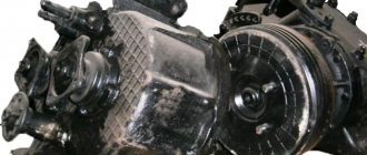
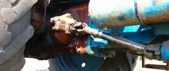
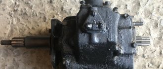
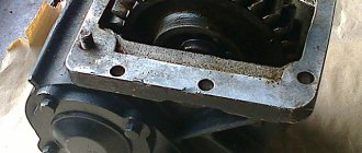
A transfer case or transfer case is a special module that is mounted on cars designed specifically for off-road and rough terrain travel. The transfer case ensures equal distribution of forces between the vehicle's drive axles. It was the GAZ 66 transfer case, the structure and design of which were the subject of special attention of the designers, that provided the car with almost legendary cross-country ability. GAZ-66 went down in the history of the domestic automotive industry as one of the most successful trucks. The design solutions implemented during its development made it possible to overcome off-road conditions that most cars cannot handle. The design of the transfer case made a significant contribution.
Checking, disassembling and assembling the GAZ-66 transfer case
The transfer case (Fig. 1) has two gears: direct and reduction.
In order to reduce the amount of work during operation, ball bearings are used in the transfer case, which do not require adjustments.
The transfer case is controlled by two levers. The left lever is used to turn on the front axle and has two positions: front - the axle is on and rear - the axle is off.
The right lever is used to change gears in the transfer case and has three positions: forward - direct transmission is engaged; neutral (middle) position and reverse - downshift is engaged.
The gear shift mechanism of the transfer case is equipped with a blocking device, which prevents the possibility of engaging a low gear when the front axle is turned off, as well as turning off the front axle when a low gear is engaged.
The locking device protects the driveline and rear axle parts from overload.
Transfer case maintenance
Caring for the transfer case during operation consists of checking the fastening, maintaining the required level of lubrication and periodically changing the oil in the crankcase.
To troubleshoot problems, in some cases it is necessary to remove the transfer case from the vehicle and disassemble it.
Depending on the nature of the malfunction, disassembly may be partial or complete.
Transfer case malfunctions and ways to eliminate them
Increased noise during transfer case operation:
— Increased lateral clearance in the gear mesh as a result of wear of their teeth
Replace worn gears
— Weak tightening of the bolts securing the bearing caps and nuts securing the cardan flanges
Tighten the bolts and nuts
— Failure to properly engage the gears due to bearing wear
Replace worn bearings
Difficult gear shifting:
— Uneven pressure in the tires of the front and rear wheels. At the same time, the front axle does not engage while the car is moving.
Equalize tire pressure
— Seizing in the transfer case control drive, which may be the result of bent or worn drive parts
Check the condition of the drive and replace unsuitable parts
— Crumples, chips at the ends of the teeth of the engaged gears, which appeared as a result of their frequent inclusion with noise and shocks
Replace unusable gears
— Jamming in the splined joints of the drive and intermediate shafts with sliding gears
Replace faulty parts
Automatic gear shifting when the vehicle is moving:
— Incorrect gear engagement, which did not ensure complete engagement of the gear teeth due to excessive wear of the forks and rods, as well as as a result of loosening of the forks on the rods
Replace worn rods and forks, ensuring the required fastening of the forks on the rods
— Misalignment of gear teeth caused by wear of the following parts: forks and rods (when shifting gears, locking is not felt); grooves for forks and splines on the gears of the rear and front axles; transfer case shaft bearings
Replace worn parts and tighten bolts.
When installing new parts, special attention must be paid to ensuring that the sliding gears fit tightly on the drive and intermediate shafts. In this case, the shafts and sliding gears should be selected so that there is no perceptible angular play of the gears when they slide freely along the splines of both shafts
— Axial movement of the transfer case shafts, as a result of loosening the bolts securing the bearing caps, which secure the shafts from axial movements.
Oil leak from transfer case housing:
— Wear of oil seals and flange surfaces on which oil seals operate
Replace worn parts
— Wear of seals on rods
Tighten the oil seal nuts
— Weak tightening of the transfer case cover bolts
— Cracks in the crankcase and covers, damage to gaskets
Replace unusable parts
— Unsatisfactory performance of the breather (contamination with dirt)
Clean the breather from dirt or replace it with a new one
Premature wear or destruction of transfer case bearings:
— Improper balancing of cardan shafts
Check the balancing of the cardan shafts and the condition of the cardan joints
— Weak tightening of the bearing cap bolts
Tighten the bearing cap bolts
Loss of the intermediate shaft locking rings:
History of the car
Development of the model that later became the GAZ-66 truck began in 1957 with the goal of replacing the first all-wheel drive Soviet truck, the GAZ-63. The design of the predecessor of the “shishigi” began to be developed even before the Great Patriotic War and began to be mass-produced in 1948, largely unifying production with the mass model GAZ-51.
But the rapid release of the “successor” to the GAZ-63 was hampered by the lack at that time of a mass-produced engine with the required power. In addition, in the same years, the Gorky Automobile Plant developed and began producing a light-class truck (with a load capacity of 1.1 tons) GAZ-62. Its design, made without a hood, attracted the attention of the military due to its reduction in overall dimensions and uniform load on the front and rear axles.
This was reflected in the implementation of the cabover scheme for the developed 2-ton GAZ-66 truck. Although the first experimental samples of this model, created in 1958, had a hood, since the beginning of the 1960s the cabin has lost this element. Moreover, the top army leadership, represented by the Commander-in-Chief of the Ground Forces, Marshal Chuikov, insisted on curtailing the production of the GAZ-62 in favor of the more capable GAZ-66.
This decision had a beneficial effect on the further history of the new product, significantly increasing the mass production of these machines. They began pre-production in 1962, and from July 1964 their production was put on the assembly line. Over the entire period, the plant produced 966 thousand GAZ-66 vehicles, until the end of their production in 1999.
Why is a transfer case needed for a GAZ 66?
00GAZ 66 is positioned as an off-road vehicle. The first modifications appeared in the 1960s. The machine has a high ground clearance (more than 300 mm), can effectively overcome road obstacles, and performs well when moving on loose soil. The ZMZ-53 model can act as a power plant for the GAZ 66. As for the transmission, there is a manual transmission with 4 steps. Also, this version of the car is equipped with a transfer case (TC).
Purpose of the Republic of Kazakhstan
The transfer case is a unit located in the engine compartment that ensures efficient transmission and division of torque. It can have coaxial and non-coaxial shaft options. Also, transfer cases differ in the drive of the drive axles. Both variants with a drive axle blocking mechanism and models supplemented with a differential drive have become widespread. As a rule, the RK is installed on versions of cars that are intended for use on rough terrain. Thanks to the transfer case, maximum cross-country ability is ensured.
The device of a transfer case on a GAZ 66 car
The GAZ 66 gearbox is a 4-speed type of transmission, supplemented by a synchronizer in 3rd and 4th gears. This unit includes mechanisms and elements that are reliable. In particular, this is a crankcase with a cover, shafts, bearings, gears. The crankcase is made of cast iron. At its bottom there is a special dirt trap, a breather. GAZ 66 has all-wheel drive and effectively overcomes bumpy terrain. It should be noted that there is a single-plate clutch, which is complemented by a hydraulic drive.
The GAZ 66 transfer case includes working elements whose function is to ensure efficient movement of the vehicle. The diagram of the box shows the connection of all its constituent elements.
It should be noted that there is a reliable differential. Thanks to the rotating gears, lubrication of the friction surfaces of the gearbox is ensured. The gears present in the block are spur gears. The synchronizer ensures silent switching of speed modes. There is a coupling on the hub teeth. Oil seals provide the necessary shaft seal. They prevent oil from leaking from the crankcase.
The need to diagnose RK
GAZ 66 is a vehicle that can be used in the oil industry and forestry. Its power reaches 120 horsepower. The engine has 8 cylinders. The transfer case present on the car is equipped with mechanisms, the interaction of which ensures the quality of the trip. The presence of fasteners related to the gearbox guarantees the prevention of spontaneous activation or deactivation of speed modes.
All components of the Republic of Kazakhstan need timely verification. We list the main problems that may occur with this unit:
- the appearance of a howling sound if movement is carried out at high speed;
- vibration from the gearbox;
- difficulty shifting or engaging gears;
- Self-switching off gears while moving.
It should be noted that the appearance of excessive noise may be due to the fact that there is a weak tightening of the mounting bolts present. Also, the problem may lie in the breakdown of the component parts of the box.
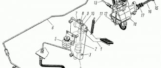
The GAZ 66 transfer case needs a full diagnosis if it becomes difficult to switch speed modes. There are several reasons for this. Firstly, you need to check the adjustment of the clutch pedal travel, and secondly, you should pay attention to the drive parts; if they are damaged, they are replaced.
As for the problem of gears switching off automatically when moving, in this case the problem may be associated with wear of the following parts:
- gear teeth;
- synchronizer clutches;
- shaft bearings.
All listed items cannot be restored and must be replaced with new similar parts.
The main reason that oil began to leak from the gearbox was weak tightening of the mounting bolts. These mechanisms should be tightened. It is also advisable to check the integrity of the crankcase, the top cover, and inspect the breather, which should not have dirt deposits.
The GAZ 66 has an inertial synchronizer, supplemented with locking rings, which includes:
- hubs;
- couplings;
- locking, wire rings;
- crackers.
The need to disassemble and reassemble the RC arises if the components associated with it are worn out.
Thus, GAZ 66 has a large load capacity and is equipped with a reliable engine and transmission. To independently repair this unit, you need good knowledge of the gearbox on the GAZ 66. Otherwise, serious damage will be caused to the automotive system. It is worth entrusting the elimination of faults in the Republic of Kazakhstan to the specialists working in the car service center.
Transfer case service
The box is subjected to severe stress during operation. Its serviceability depends on compliance with the rules of use and constant prevention.
The main symptoms of a faulty mechanism:
- Additional noise and vibration.
- Difficulty turning control levers on or off.
- Spontaneous shutdown of the mode on the go.
- Oil stains on the body, oil leakage.
To detect them in time, it is necessary to regularly:
- Visual inspection of the box.
- Adding oil to the crankcase.
- Checking and correcting fastening tightening.
These simple steps will not take much time, but will allow you to detect the first signs of malfunctions and eliminate them in a timely manner.
The main causes of problems and ways to fix them:
- Insufficient oil level in the crankcase or its quality is inadequate. You need to regularly check the oil level and top up if necessary. Buy lubricants only from trusted suppliers.
- Wear of teeth of drive mechanisms. Minor damage is eliminated by grinding, large damage by replacing parts.
- Faulty fork attachment or worn out connecting rods.
- Broken clutch module. In this and the above cases, failed parts must be replaced.
- Wear of gaskets and seals. These parts need to be changed in a timely manner, since their service life is short. You should always have a supply of consumables and lubricants.
The transfer case and gearbox of the GAZ 66 are quite complex so that repairs can be carried out without proper experience. If you don’t have experience in DIY repairs and don’t have the necessary tools, it’s better to contact a car service center. However, if you have experience successfully working with truck components, you can begin repairs by first studying the instructions and watching training videos.
Selection of transmission oil for GAZ 66
The GAZ 66 gearbox can prematurely lose its properties if you use poor quality oil that is not suitable for this gearbox.
What kind of oil is needed for the GAZ 66 gearbox and transfer case? For “mechanics”, 3 liters are required, as for the transfer case, approximately 1.5 liters are added to it. Among the transmission fluids it is worth highlighting: TAp-15V, TSp-15K. The replacement interval is approximately 60,000 km. For preventive purposes, the quantity and quality of oil should be checked every 15,000 km.
Transfer cases
The power taken from the engine through the clutch and gearbox is sent to the vehicle's drive wheels through the driveshaft and final drive. For cars with one drive axle, in this case, the power flow follows in one direction, but for cars with two or more drive axles, it is necessary to distribute the engine power between all drive wheels in proportion to the load they overcome. In such cars, transfer cases are used to distribute torque between the drive axles. In addition, installing a reduction gear in the transfer case can significantly increase the transmitted torque and traction force, helping to increase the vehicle's cross-country ability. Therefore, many transfer cases are capable of performing two main functions - distributing torque from the engine between all drive wheels, as well as changing, if necessary, the amount of transmitted torque.
Transfer cases are classified according to a number of criteria:
- according to the number of gears - single-stage and two-stage;
- according to the location of the driven shafts - coaxial and non-coaxial;
- for driving driven shafts - with a non-differential (locked) drive and with a differential drive.
The main types of transfer cases are shown in Fig. 1.
Single-speed transfer cases are usually used on all-wheel drive passenger cars, where a significant increase in traction force can lead to unwanted overloads of the transmission units.
A two-speed transfer case doubles the number of gears and expands the range of gear ratios; it is used on trucks to improve traction qualities. In fact, such a transfer case is not only a power flow distributor, but also a kind of multiplier that increases the dynamic capabilities of the car by increasing the traction force on the drive wheels.
Transfer cases with coaxial shafts are most widely used, since it is easy to carry out differential drive of driven shafts in them by installing center differentials. In addition, with the help of an asymmetrical differential, torque can be distributed between the drive axles in proportion to the vertical loads on them.
The differential drive of the driven shafts allows the wheels of different axles to rotate at different angular speeds, which eliminates the circulation of power in the transmission. In such transfer cases, the front axle is constantly engaged, which simplifies control of the transfer case. However, in certain conditions, on a car with a non-locking cross-axle differential, if one of the wheels slips, movement will be impossible. Therefore, there must be a device for locking the center differential.
Misaligned transfer cases are usually differentialless. Since the wheels of different axles travel different paths when a car moves on uneven roads, when the front axle is engaged this leads to power circulation. Therefore, the front axle must be disengaged when driving on paved roads to prevent significant tire wear. In addition, such transfer cases must have a device that blocks downshifting when the front axle is off. This is done in order to prevent excessive torque from being transmitted to the rear axle or rear bogie.
Project of a vehicle fleet for vehicle maintenance
A specific type of tire radial overload is dynamic loads due to wheel imbalance. A sign that a wheel is unbalanced is wear on the tire tread. Wheel imbalance depends on the tire itself, the rim, and the wheel hub.
The internal air pressure in a tire has a significant impact on its durability. The optimal air pressure value is set by the manufacturer based on final testing of the vehicle, taking into account the requirements for handling, smoothness and durability of the tire itself. On average, the nature of the influence of air pressure in a tire on its service life is shown in Fig. 2.48.
As the air pressure in the tire decreases, the deformation of the carcass increases and, due to hysteresis losses, the tire temperature during operation increases. As a result, the strength of tire materials decreases, delamination and chafing of the cord threads are possible. The tread wear is uneven (the shoulder area of the tire wears out more).
4. Repair of the GAZ-66 transfer case
4.1 Purpose and design of the GAZ-66 transfer case
To increase the cross-country ability of vehicles, all their axles are made to be leading. On such cars, in addition to the gearbox, a transfer case is installed, the purpose of which is to transmit torque from the engine evenly to all drive axles. The transfer case has a reduction gear to increase the forces on the drive wheels and a device for turning the front drive axle on and off. One of the transfer cases is shown in Fig. 8 (GAZ-66 car).
From the gearbox, the movement is transmitted via a cardan transmission through a flange to the drive shaft / transfer case. A direct and reduction gear 2 is installed on the drive shaft on the splines. The reduction gear 8 is rigidly fixed on the intermediate shaft 4 and the movable gear 5 for engaging the front axle is mounted on the splines. A gear is fixedly mounted on splines on the front axle drive shaft 7.
The front axle is activated by moving the intermediate shaft moving gear backwards. In direct transmission, the drive shaft gear moves backward along the splines, and its teeth mesh with the internal teeth of the driven shaft gear. Downshift is engaged by moving the drive shaft gear forward so that the teeth mesh with the countershaft gear.
Rice. 8. Transfer case of the GAZ-66 car:
/—drive shaft; 2 — gear for engaging forward and downshift gears; 3— rear axle drive shaft; 4 - intermediate shaft; 5 — front axle engagement gear; 6 - crankcase; 7—front axle drive shaft; 8—reduction gear.
The gear shift mechanism is located on the cover and consists of two sliders and forks, which are actuated by two additional levers in the driver's cab. Before engaging a downshift in the transfer case, the front axle must be engaged, otherwise the gear will not engage.
In order not to engage the transfer case in low gear when the front axle is turned off, a locking device with two pins and a spring is installed in the housing opening. This eliminates the possibility of overloading the rear drive axle with high torque when downshifting the transfer case.
The front axle can be engaged without downshifting. Ball retainers are used to hold the gears in the on or off position.
The three-axle GAZ-66 with all-wheel drive has a transfer case with two gears, direct and reduction. The front axle is switched on automatically by an electro-pneumatic valve when downshifting in the transfer case. When direct transmission is engaged, the front axle is forcibly turned off by a switch installed on the front instrument panel. Turning on the front axle is accompanied by the warning lamp on the instrument panel coming on.
In the transfer cases of three-axle vehicles Ural-375D and KrAZ-255B, a center differential is installed that distributes the torque supplied to it from the engine through the gearbox between the middle and rear drive axles. The transfer case of these cars is two-stage, with high and low gears.
To lubricate the gearbox and transfer case, special transmission oils are used, recommended in the factory instructions (for example, TAp-15, TA-10, etc.). These oils have high viscosity and a low pour point.
4.2 Malfunctions of the gearbox and transfer case
During the operation of the car, parts, especially gears and parts of the switching mechanism, wear out intensively. As a result, malfunctions such as spontaneous gear shifting, difficulty turning on and off, and increased noise when the vehicle is moving may occur.
Gears switch off spontaneously when the gear teeth and parts of the locking device of the gearbox and transfer case are severely worn. The malfunction is eliminated by replacing parts.
Difficulties when turning gears on and off arise due to wear of bearings and splined joints, causing gear misalignments, or misalignment of the gearbox control mechanism and transfer case.
Increased noise in the gearbox and transfer case can occur due to a lack of oil in the crankcase, wear of bearings, teeth and gear seats.
Cardan transmission
The cardan drive (Fig. 9) connects the gearbox and the main gear, the shaft axes of which are located in different planes and the distance between them is constantly changing while the car is moving. This is due to the fact that the gearbox is rigidly attached to the engine, fixedly mounted on the frame of the car, and its drive axle is attached to the frame on springs, which, by springing, allow the distance between the axle and the frame to change. Transmission of torque under such conditions is possible only with universal joints (universal joints) and sliding spline joints.
Rice. 9. Location of the driveshaft on the car:
/, 3 and 6 - cardan joints; 2 - main shaft; 4 - intermediate support; 5— intermediate shaft; 7 - forks; 8 - cross.
The cardan transmission of the GAZ-66 car is shown in Fig. 10. On cars where the distance between the gearbox and the main drive is large, two driveshafts are used - intermediate 5 and main 10. The intermediate shaft allows you to make the main shaft shorter and more rigid and reduce the possibility of its vibration. The intermediate shaft, connected to the driven shaft of the gearbox by a cardan, is suspended on a support, which consists of a housing attached to the frame cross member and a ball bearing 21, closed with stamped steel covers and seals. The bearing with caps is installed in a rubber cushion 6.
Two cardan shafts are installed on the main cardan shaft. Rotational motion with variable frequency is transmitted through the front shaft. To eliminate the resulting uneven rotation, a rear cardan is installed at the other end of the shaft. Each cardan consists of a cross 3 and two forks 14 and 17. A cardan with a sliding tip is called a universal cardan. Needle bearings installed in the fork holes reduce friction on the spider axles. The splined (telescopic) connection 13 of the intermediate shaft allows you to change the length of the cardan transmission, since during movement the distance between the gearbox and the drive axle changes not only vertically, but also horizontally. The spline end of the universal driveshaft fits into a splined sleeve welded to the rear end of the countershaft. The splined bushing is filled with lubricant through a grease nipple 11 and sealed with a seal ring 8, which is screwed onto the intermediate shaft 5. To install the cardan forks in the same plane, marks in the form of arrows are applied to the shaft 5 and the universal cardan.
The cardan transmission of the GAZ-66 car is designed in the same way as the cardan transmission of the GAZ-66 car.
\
Rice. 10. Cardan transmission of the GAZ-66 car:
/ - safety valve; 2 — needle bearing cover; 3 — cross; 4 — cork seal of the needle bearing; 5 — intermediate cardan shaft; 6—rubber support pad; 7 — felt seal of the support bearing; 8 — sliding fork seal ring; 9 — sliding fork; 10-. main driveshaft; // and 15—greasing nipple; 12 — ball bearing; 13 — spline connection of the intermediate shaft; 14 and 17 - forks; 16 — needle bearing.
On a GAZ-66 car, the cardan transmission consists of three driveshafts with two universal joints on each. Intermediate shaft 4 (Fig. 11) transmits torque from the gearbox to the transfer case, front shaft 3 - from the transfer case to the front axle, and rear shaft 6 - from the transfer case to the rear drive axle.
The cardan transmission of the GAZ-66 car consists of four cardan shafts with two cardan joints on each. Intermediate shaft 2 transmits torque from the gearbox / to transfer case 3, shaft 8 of the front axle - from the transfer case to the front drive axle 9, and shafts 4 and 6 - to the middle axle 5 and rear axle 7.
On the three-axle Ural-375D vehicle, the cardan transmission is made similar to the cardan transmission of the GAZ-66- car; on the KrAZ-255B vehicle with a drive on all three axles, a transmission with parallel drive of the middle and rear drive axles is used.
Rice. 11. Cardan transmission of the GAZ-66 car:
1 — front drive axle; 2 — gearbox; 3—front driveshaft; 4—intermediate cardan shaft; . 5—transfer case; 6 — rear propeller shaft; 7—rear drive axle.
The needle bearings of the cardan crosspieces are lubricated using grease nipples screwed into a threaded hole in the center of the crosspiece. On the opposite side of the crosspiece, in its center, there is a safety valve that releases excess grease when the crosspiece and bearings are filled, which protects the seals that protect the needle bearings from leaking grease from damage. The spline joint and the intermediate shaft bearing are also lubricated.
continuation
www.coolreferat.com
Transfer case GAZ-66
A transfer case is usually called a car module, which is responsible for the uniform distribution of rotational forces between both axles of the car. This design is used in cars designed for cross-country travel.
GAZ-66 transfer case diagram
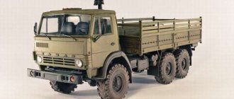
The GAZ-66 car or, as it is popularly called, “Shishiga” is one of the most successful trucks of the GAZ automobile plant. And this is fair, its design solutions for organizing the main components and assemblies, in particular the transfer case, allow you to overcome off-road conditions that most cars cannot handle.
Appearance of GAZ-66
Design of the GAZ-66 transfer case
Since the transfer case is externally and functionally similar to the transmission box, it got its name transfer case.
Its main purpose is to distribute the load evenly across all axles of the vehicle, as well as to enhance the applied torque forces. Depending on the type of vehicle, the transfer case may have either only the function of connecting the front axle, or an additional downshift.
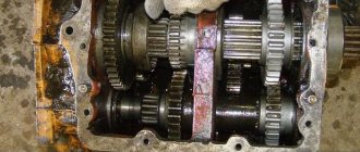
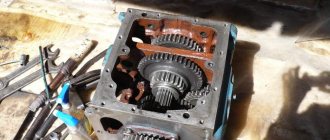
This is what a disassembled GAZ-66 transfer case looks like
The transfer case on the GAZ-66 provides the ability to drive in low gear. To do this, it is equipped with two shift levers, which provide control over the inclusion of operating modes of axles and gears when driving, including:
- The first lever (on the left side): there are two possible positions, it is responsible for activating the front axle, while the forward position means the simultaneous operation of two axles.
- The second lever (on the right side) has three positions:
- w Neutral.
- w Extremely forward when the main direct drive is engaged.
- w Rear, designed for driving with downshifts.
The GAZ-66 transfer case belongs to the type that is equipped with a locking device with the function of preventing the engagement of a lower gear when the front axle is not active.
The transfer case has gear ratios of 1.98 and 1, respectively for low and direct transmission.
The transfer case consists of the following components:
- A drive shaft device to which motion from a cardan drive is transmitted via a flange.
- Gear for engaging direct and low gear.
- Rear axle drive, which is a shaft with pre-installed double-sided gears.
- The intermediate shaft, the connecting shaft, has a movable gear mechanism (gear) and is responsible for engaging the front axle, as well as low gear.
- Front axle drive with gear necessary to directly provide connection to the front axle.
- Carter, protective box with hole for oil filling.
- Lever-traction control mechanism.
The operation of the GAZ-66 transfer case is based on the principle of moving gears to different positions through traction control, which ensures engagement with a specific drive gear.
This design is used on a two-axle, standard version of the car.
The three-axle version of the GAZ-66 includes a transfer case with two positions for the downshift lever. In the downshift position, the front axle is automatically connected by actuating an electromagnetic valve. The instrument panel in the cockpit is equipped with an indication of the operation of the additional axle and a key for its forced shutdown during direct transmission.
Description and principle of operation of the distributor
The transfer case is similar to the transmission box in terms of both appearance and functionality. Its main purpose is to distribute loads evenly across all bridges. Depending on the type of vehicle, the transfer case can be connected only to the front axle or also to a low gear.
The operating principle is as follows:
- When the clutch is engaged, torque is transmitted to the transfer case drive shaft and then to the rear wheels. This is ensured by the meshing of the carriage gear with the corresponding gears.
- If there is no engagement, then torque will not be transmitted to the wheels.
- Also, the engagement of the carriage gear with the proper gear ensures that the downshift is engaged. Used when driving on sticky soil or uphill under load. As a result, traction forces on the wheels increase and cross-country ability increases. This only works in all-wheel drive to avoid overloading the rear axle drive.
The transfer case helps distribute the load evenly
