How to diagnose
Diagnostics includes collecting signs of problems in the system, scanning the electronic control system, resetting and checking all mechanisms and systems for faults in the electronic unit, inspecting all sensors that are responsible for the uninterrupted operation of the power unit.
During diagnostics of KamAZ-5490, 54115, 5308 and other models with an engine manufactured according to the international environmental standards Euro-3 and 4, the pressure level in the fuel system is measured, the performance of the generator set is tested and exhaust gases are analyzed using special equipment. They also check the winding of the electromagnetic regulator of the fuel supply system and the short circuit in the inductive sensor coils.
Equipment and programs for diagnostics
There are several scanners for detecting problems in vehicle mechanisms, for example:
- Autoscanner DK-5. This equipment helps detect problems in the electronic unit by reading and adjusting control system indicators using a computer. This autoscanner can be used at temperatures up to +30°C and relative humidity no more than 80%.
- Scanner EDS-24. This is a software and hardware complex designed for computer diagnostics of a cargo vehicle. It includes a USB adapter with galvanic isolation, which makes it possible to test systems in low voltage conditions.
Diagnostic programs:
Error spn 523613 fmi 16
Error codes for KamAZ Euro-4 are information about problems with the operation of the vehicle.
How to diagnose
Diagnostics includes collecting signs of problems in the system, scanning the electronic control system, resetting and checking all mechanisms and systems for faults in the electronic unit, inspecting all sensors that are responsible for the uninterrupted operation of the power unit.
During diagnostics of KamAZ-5490, 54115, 5308 and other models with an engine manufactured according to the international environmental standards Euro-3 and 4, the pressure level in the fuel system is measured, the performance of the generator set is tested and exhaust gases are analyzed using special equipment. They also check the winding of the electromagnetic regulator of the fuel supply system and the short circuit in the inductive sensor coils.
Equipment and programs for diagnostics
There are several scanners for detecting problems in vehicle mechanisms, for example:
- Autoscanner DK-5. This equipment helps detect problems in the electronic unit by reading and adjusting control system indicators using a computer. This autoscanner can be used at temperatures up to +30°C and relative humidity no more than 80%.
- Scanner EDS-24. This is a software and hardware complex designed for computer diagnostics of a cargo vehicle. It includes a USB adapter with galvanic isolation, which makes it possible to test systems in low voltage conditions.
Decoding errors
The decoding of KamAZ error codes is presented in the instructions for the program, which is used for diagnostics. Examples of errors:
- 213 - malfunction of the power unit control device;
- 296 - oil pressure has dropped;
- 2973 - failures in the air pressure control system in the intake manifold;
- 214 - overheating of the oil fluid;
- 235 - insufficient amount of coolant in the system;
- 425 - high oil temperature;
- 3617 - there is no signal from the multi-stage switch;
- error 4335 - problems with air supply;
- 275 - fuel injection pump is not working correctly;
- 429 - high voltage in the fuel indicator circuit;
- 351 - malfunction of the injectors;
- 415 - low level of working fluid;
- 261 - fuel overheating.
Sensor failures
Fault codes for KamAZ-34334, 6308 and other models with Euro-4 engines:
- 221 - a breakdown in the pedal position sensor, which is responsible for the supply of working fluid;
- 232 - malfunction of the sensor measuring atmospheric pressure;
- 335 - defects in the wiring of the lamp control output stage;
- 231 - malfunction of the boost pressure sensor on the electrical control unit;
- 124 — fixing an incorrect voltage indicator;
- 345 - incorrect operation of signal transmission from the exhaust gas pressure indicator;
- 113 - problems with camshaft speed;
- 112 - incorrect indicators supplied to the control unit from the crankshaft;
- 246 - malfunction of the temperature sensor;
- 00550 - malfunction of the fuel injection pump plug.
ICE malfunctions
List of internal combustion engine breakdowns on KamAZ:
- 726 FMI 2 - malfunction of the position indicator of the device responsible for liquid distribution;
- SPN 526313 FMI 6 - defective device that controls the pressure level in the ramp mechanism;
- SPN 520211 FMI 12 - no message from the ABS system;
- SPN 791 FMI 4 - low charge level;
- 523470-2 - there is no voltage in the circuit of the mechanism responsible for resetting the pressure indicators;
- SPN 523613 FMI 16 - working fluid filters are worn out;
- 77 FMI 0 - high engine speed;
- 190-3 - malfunction;
- 110-0 — high level of motor temperature;
- 132-4 - failure in air flow distribution;
- 653-0 - damage to the injector power supply system.
Other breakdowns
| System error codes | Cause of failure |
| SPN 977 FMI 4 | Malfunctions in the operation of the air conditioner chain mechanism |
| 98-1 | The number of crankshaft revolutions has been exceeded |
| 523601-4 | Low fuel and oil level |
| 3514-31 | The power supply has failed |
| 675-4 | Injectors are closed |
| 13688-4 | Fuel pump relay shorted to ground |
| 91-4 | Fuzzy signal from the sensor responsible for the position of the brake mechanism |
| 171-3 | This error stands for a malfunction of the thermometer |
| 1072-4 | The valve was shorted to ground |
| 111-3 | Strong signal from the antifreeze level indicator |
| 1188-5 | There is no connection with the air flow heating relay |
| 110-2 | The sensor monitoring the antifreeze temperature is not working correctly |
| 1188-4 | There is a short to ground in the pressure valve control circuit. |
How to reset errors
Resetting on KamAZ-4334, 5308 and other models can be done as follows:
- Warm up the engine to operating temperature.
- Remove the positive terminal from the battery for 5-15 minutes.
- Connect the terminal back to the battery.
- Turn the ignition key to the last position before starting the engine from the starter. In this case, the lights and indicators located on the dashboard should light up.
- Leave the key in this position for 1 minute.
- Return the ignition key to its original position.
If this does not help, then a short circuit should be made in the vehicle circuit. In this case, after resetting, you will have to replace the safety element.
Is a serious vehicle exhibiting inappropriate behavior? The vagaries of your truck can ruin business deals and lead to long periods of downtime, draining your wallet. In this article, we will tell you how to diagnose problems at an early stage in order to begin troubleshooting problems in a timely manner.
How to diagnose faults on a KAMAZ truck?
Is a serious vehicle exhibiting inappropriate behavior? The vagaries of your truck can ruin business deals and lead to long periods of downtime, draining your wallet. In this article, we will tell you how to diagnose problems at an early stage in order to begin troubleshooting problems in a timely manner.
Recently, engines from the Kama Automobile Plant began to be classified according to their belonging to one or another environmental class (from Euro-0 to Euro-4). The technical implementation of the Euro-3 class, and then Euro-4, adopted in 2013, turned out to be impossible without the use of electronic engine control systems (ECM). This is what led to the opportunity to perform self-diagnosis of the car using KAMAZ universal error codes.
Ecological class Euro-4
Various configurations of KAMAZ trucks began to be equipped with engines with electronic control units (ECU). And if now the driver is concerned about unhealthy behavior during the operation of famous trucks, symptoms appear in the form of floating speed, loss of traction, unusual noises, increased diesel fuel consumption, self-diagnosis comes to the rescue.
Using information output from the ECU in the form of an error code, it is possible to indicate an accurate electrical diagnosis for KAMAZ. The process of diagnosing and deciphering codes depends on the type of electronic system installed on the truck. Before starting diagnostics, it is suggested to determine the type of ECU based on the installed engine model.
Engine Model Table
Self-Diagnostics No matter what company your V8 is made by, Cummins Inc. (Cummins) or KAMAZ LLC, it is equipped with fuel supply systems from Common Rail and exhaust gas recirculation (EGR) or neutralization systems (SCR), diagnostics will be carried out in accordance with these two types.
Engine with ECU BOSCH MS 6.1
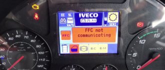
So, let’s get comfortable in the cabin of our KAMAZ, then turn on the ignition with the usual turn of the key. Along with many other indicators, the diagnostic indicator light or “Check Engine”, or in common parlance, a submarine, lights up. The lamp lights up for 3 seconds and goes out, thereby demonstrating its functionality and the serviceability of the ECM. If the lamp does not go out or lights up while the engine is running, a malfunction has been found in the electronic system!
Diagnostic indicator lamp
Let's pay attention to the diagnostic mode rocker button (often mounted on the instrument panel on the left, under the steering wheel) or the button for this mode (often located next to the fuse box, under the panel opposite the passenger seat). The “rocker” has two extreme positions for holding and a central fixed position.
Diagnostic mode rocker button Diagnostic mode button
Lower the rocker to its highest or lowest position and hold it there for more than two seconds. Just press the button and do not release it for the above-mentioned time. After the rocker or button returns back, the diagnostic lamp will flash first in long intervals and then in short ones. The number of long flashes determines the first digit of the error code, the number of short flashes determines the second digit.
Blink Code Alarm Diagram
The diagram shows an example of obtaining code 24. We compare the error code (otherwise blink code, from the English blink - blink) with the table below.
| Error codes for the BOSCH MS6.1 ECU of Euro-3 eco-class engines | ||
| Error code | Description of the malfunction | Operating restrictions set by the ECU |
| 11 | gas pedal | engine speed is limited to 1900 rpm |
| 12, 13 | atmospheric pressure sensor | not limited |
| 14 | clutch sensor | engine speed is limited to 1900 rpm |
| 15 | crankshaft rotation frequency sensor | engine speed is limited to 1600 rpm |
| 16, 17 | Incorrect polarity of frequency rotation sensors; sensors are not installed correctly | engine speed is limited to 1800 rpm |
| 18 | frequency camshaft rotation sensor | engine speed is limited to 1800 rpm |
| 19 | main relay | not limited |
| 21, 22, 24—26 | high pressure fuel pump | engine start failure |
| 23 | inappropriate position of the gas and brake pedals | not limited |
| 27 | poor contact of rack position sensor | engine start failure |
| 28 | brake pedal sensor | not limited |
| 29, 51—53, 81—86, 99 | electronic control unit | engine start failure |
| 31, 32 | air temperature sensor | not limited |
| 33, 34 | air pressure sensor | not limited |
| 35 | cruise control module | not limited |
| 36, 37 | liquid cooling temperature sensor | engine speed is limited to 1900 rpm |
| 38, 39 | fuel temperature sensor | engine speed is limited to 1900 rpm |
| 41 | the signal from the multi-stage input does not correspond to the reference | not limited |
| 42 | maximum engine speed exceeded | The wrong gear may have been selected. Resetting the error when starting the engine again |
| 43 | speed signal error | engine speed is limited to 1500 rpm |
| 54 | excess on-board voltage | not limited |
| 55 | The control unit operation cycle is not completed correctly | not limited |
| 61—67 | CAN line | not limited |
There are often cases when the ECU has recorded several errors; to view the following code, repeat the above steps with the button or rocker. Error codes will be played cyclically. No more than five faults are recorded in the ECU memory. To delete all errors from the control unit’s memory, you must turn on the ignition and hold the “rocker” for five seconds. Thus, you can briefly rid your car of disturbing symptoms in the form of electronic restrictions.
Engine with ECU ISB CM2150
This type of ECU was installed on later KAMAZ models and the diagnostics in this case will differ from the above diagram. After turning on the ignition, the currently active fault is recorded in the memory of the electronic unit; in addition, the fault can be signaled by a red or yellow diagnostic control lamp.
Yellow and red diagnostic indicator lamps
After pressing the “rocker” in any extreme position for more than two seconds, a fault code will be displayed with a half-second interval between flashes of one of the two lamps. The error code digits are separated by a 2-second pause. Unlike the previous type of ECU, the resulting code will be three or four digits!
We compare the error code with the table below. The color of the rows in the table is correlated with the color of the diagnostic control lamp. The red color of the indication indicates the impossibility of starting or continuing driving with this malfunction; the yellow color indicates the need to eliminate the malfunction after finishing driving the vehicle.
| Error codes for ECU ISB CM2150 of Euro-3 eco-class engines | |||||
| 111 | Critical failure inside the engine control module - the intelligent programmable or its component is not working correctly | 422 | Coolant Level - Errors Coming | 689 | Error in the primary engine speed sensor - errors are received |
| 115 | In the engine speed (position) sensor circuit, loss of a pair of signals from the electromagnetic sensor - errors are received | 425 | Engine lubricant temperature - erroneous data received | 1139 | Injector Cylinder #1 - Mechanical system not firing properly or out of adjustment |
| 143 | Low oil pressure - reliable data, but below the optimal operating range | 428 | Water in the fuel sensor circuit - voltage is higher than normal, or the circuit is shorted to a high voltage source | 1141 | Injector Cylinder #2 - Mechanical system not firing correctly or out of adjustment |
| 146 | Coolant temperature is above normal - reliable data, but above the optimal operating range | 429 | Water entering the fuel sensor circuit - the voltage is higher than normal, or the circuit is short-circuited to a low voltage source | 1142 | Injector Cylinder #3 - Mechanical system not firing correctly or out of adjustment |
| 151 | Coolant temperature below normal - reliable data, but above optimal operating range | 431 | Idle Check Circuit, Accelerator Pedal or Lever - Data Received with Errors | 1143 | Injector Cylinder #4 - Mechanical system not firing correctly or out of adjustment |
| 197 | Coolant level - reliable data, but below optimal operating range | 432 | Idle Check Circuit, Accelerator Pedal or Lever - Uncalibrated | 1144 | Injector Cylinder #5 - Mechanical system not firing correctly or out of adjustment |
| 214 | Engine oil temperature - reliable data, but above the optimal operating range | 433 | Intake Manifold Pressure Sensor Circuit - Incorrect Values Coming | 1145 | Injector Cylinder #6 - Mechanical system not firing correctly or out of adjustment |
| 233 | Coolant pressure - reliable data, but below optimal operating range - moderately intense level | 434 | Power failure without turning off the ignition (Ignition Off) - errors are received | 2265 | Starting pump control signal circuit - voltage is higher than normal, or shorted to a high voltage source |
| 234 | High engine speed - reliable data, but above the optimal operating range | 435 | Oil Pressure Sensor Circuit - Errors Coming | 2266 | Start Pump Control Signal Circuit - Voltage Below Normal or Shorted to Low Voltage Source |
| 235 | Coolant deficiency - good data, but below optimal operating range | 441 | Low Battery Voltage #1 - Valid data, but below optimal operating range | 2292 | Fuel metering device - reliable data, but above the optimal operating range |
| 245 | Fan Control Circuit - Voltage Below Normal or Shorted to Low Voltage Source | 442 | Battery #1 High Voltage - Valid data, but above optimal operating range | 2293 | Fuel metering device - flow requirement lower than expected - reliable data, but below optimal operating range |
| 261 | Engine fuel temperature - reliable data, but above optimal operating conditions | 449 | High fuel pressure - reliable data, but above the optimal operating range | 2377 | Fan Control Circuit - Voltage High or Shorted to High Voltage |
| 275 | Fuel Injection Element (Front) - Mechanical system does not operate correctly or is not adjusted | 595 | Turbocharger #1 high speed - reliable data, but above optimal operating range | 2555 | Intake air heater circuit No. 1 - voltage is higher than normal, or shorted to a high voltage source |
| 281 | Solenoid Controlled High Pressure Fuel No. 1 Valve - Mechanical System Not Actuating Correctly or Out of Adjustment | 596 | Electrical charging system voltage high - reliable data, but above optimal operating range | 2556 | Intake air heater circuit No. 1 - voltage below normal, or shorted to a low voltage source |
| 351 | The injector power supply is a faulty intelligent programmable device or component. | 598 | Electrical charging system voltage low - reliable data, but below optimal operating range | 2558 | Auxiliary PWM (Pulse Width Modulation) Trigger #1 - Voltage Below Normal or Circuit Shorted to Low Voltage Source |
| 415 | Low oil pressure - reliable data, but below optimal operating range | 687 | Low speed of turbocharger No. 1 - reliable data, but below the optimal operating range | 2973 | Intake Manifold Pressure Sensor Circuit - Incorrect Data Received |
If you do not find your engine brand or error code for the ISB CM2150 ECU in the table, be sure to write to us and we will immediately try to help.
Electronic control systems KAMAZ
Recently, engines from the Kama Automobile Plant began to be classified according to their belonging to one or another environmental class (from Euro-0 to Euro-4). The technical implementation of the Euro-3 class, and then Euro-4, adopted in 2013, turned out to be impossible without the use of electronic engine control systems (ECM). This is what led to the opportunity to perform self-diagnosis of the car using KAMAZ universal error codes.
Ecological class Euro-4
Various configurations of KAMAZ trucks began to be equipped with engines with electronic control units (ECU). And if now the driver is concerned about unhealthy behavior during the operation of famous trucks, symptoms appear in the form of floating speed, loss of traction, unusual noises, increased diesel fuel consumption, self-diagnosis comes to the rescue.
Using information output from the ECU in the form of an error code, it is possible to indicate an accurate electrical diagnosis for KAMAZ. The process of diagnosing and deciphering codes depends on the type of electronic system installed on the truck. Before starting diagnostics, it is suggested to determine the type of ECU based on the installed engine model.
Engine Model Table
Self-Diagnostics No matter what company your V8 is made by, Cummins Inc. (Cummins) or KAMAZ LLC, it is equipped with fuel supply systems from Common Rail and exhaust gas recirculation (EGR) or neutralization systems (SCR), diagnostics will be carried out in accordance with these two types.
The process of self-diagnosis of KAMAZ electronic systems in Euro-3, -4 engines differs slightly from a similar procedure in other vehicles. After pressing a certain button, one of the lamps on the dashboard or indicator unit will begin to blink at different intervals; the number of flashes of the lamp at one interval determines the digit of the code.
Engine with ECU BOSCH MS 6.1
So, let’s get comfortable in the cabin of our KAMAZ, then turn on the ignition with the usual turn of the key. Along with many other indicators, the diagnostic indicator light or “Check Engine”, or in common parlance, a submarine, lights up. The lamp lights up for 3 seconds and goes out, thereby demonstrating its functionality and the serviceability of the ECM. If the lamp does not go out or lights up while the engine is running, a malfunction has been found in the electronic system!
Diagnostic indicator lamp
Let's pay attention to the diagnostic mode rocker button (often mounted on the instrument panel on the left, under the steering wheel) or the button for this mode (often located next to the fuse box, under the panel opposite the passenger seat). The “rocker” has two extreme positions for holding and a central fixed position.
Lower the rocker to its highest or lowest position and hold it there for more than two seconds. Just press the button and do not release it for the above-mentioned time. After the rocker or button returns back, the diagnostic lamp will flash first in long intervals and then in short ones. The number of long flashes determines the first digit of the error code, the number of short flashes determines the second digit.
Blink Code Alarm Diagram
The diagram shows an example of obtaining code 24. We compare the error code (otherwise blink code, from the English blink - blink) with the table below.
| Error codes for the BOSCH MS6.1 ECU of Euro-3 eco-class engines | ||
| Error code | Description of the malfunction | Operating restrictions set by the ECU |
| 11 | gas pedal | engine speed is limited to 1900 rpm |
| 12, 13 | atmospheric pressure sensor | not limited |
| 14 | clutch sensor | engine speed is limited to 1900 rpm |
| 15 | crankshaft rotation frequency sensor | engine speed is limited to 1600 rpm |
| 16, 17 | Incorrect polarity of frequency rotation sensors; sensors are not installed correctly | engine speed is limited to 1800 rpm |
| 18 | frequency camshaft rotation sensor | engine speed is limited to 1800 rpm |
| 19 | main relay | not limited |
| 21, 22, 24—26 | high pressure fuel pump | engine start failure |
| 23 | inappropriate position of the gas and brake pedals | not limited |
| 27 | poor contact of rack position sensor | engine start failure |
| 28 | brake pedal sensor | not limited |
| 29, 51—53, 81—86, 99 | electronic control unit | engine start failure |
| 31, 32 | air temperature sensor | not limited |
| 33, 34 | air pressure sensor | not limited |
| 35 | cruise control module | not limited |
| 36, 37 | liquid cooling temperature sensor | engine speed is limited to 1900 rpm |
| 38, 39 | fuel temperature sensor | engine speed is limited to 1900 rpm |
| 41 | the signal from the multi-stage input does not correspond to the reference | not limited |
| 42 | maximum engine speed exceeded | The wrong gear may have been selected. Resetting the error when starting the engine again |
| 43 | speed signal error | engine speed is limited to 1500 rpm |
| 54 | excess on-board voltage | not limited |
| 55 | The control unit operation cycle is not completed correctly | not limited |
| 61—67 | CAN line | not limited |
KAMAZ error codes - Explanation. Symptoms. Causes
All errors KAMAZ 4307, 4308, 4311, 43255, 4350, 5308, 53215, 54115, 5460, 5490, 63698 Typhoon-K, 6460, 65111, 65115, 65117, 6520, 65201, 652 06, 65207, 6522, 65225, 6540, 6560, 6580, 65806.
Electronic control units (ECU)
740 E3 BOSCH MS6.1, 740 E4 BOSCH EDC7UC31, 820 E4 M20.21, YaMZ-656 E3 Elara 50.3763, YaMZ-656 E3 M230 E3, MB OM457LA E5 MR2, CUMMINS
Two-digit codes
9 — Malfunction of the on-board control unit EEPROM memory module
11 — Malfunction in the electrical circuit of the gas pedal
12 — Malfunction in the electrical circuit of the atmospheric pressure sensor (the sensor is built into the electronic control unit)
13 — Physical error of the atmospheric pressure sensor
14 — Malfunction in the electrical circuit of the clutch sensor
15 — Malfunction in the electrical circuit of the main engine speed sensor (crankshaft)
16 — Incorrect polarity or reversal of engine speed sensors
17 — Incorrect polarity or reversal of engine speed sensors
18 — Malfunction in the electrical circuit of the auxiliary engine speed sensor (camshaft)
19 — Malfunction in the electrical circuit of the main relay for turning on the electronic control unit
21 — Malfunction in the electrical circuit of the injection pump (high pressure fuel pump)
22 — Malfunction in the electrical circuit of the injection pump (high pressure fuel pump)
23 — Inconsistency between the position of the gas pedal and the brake pedal
24 — Malfunction in the electrical circuit of the injection pump (high pressure fuel pump)
25 — Malfunction in the electrical circuit of the injection pump (high pressure fuel pump)
26 — Malfunction in the electrical circuit of the injection pump (high pressure fuel pump)
27 — Malfunction in the electrical circuit of the rack position sensor (the sensor is built into the injection pump actuator)
28 — Malfunction in the electrical circuit of the brake pedal sensor
29 — Malfunction of the electronic control unit (hardware)
31 — Malfunction in the electrical circuit of the charge air temperature sensor
32 — Physical error of the charge air temperature sensor
33 — Malfunction in the electrical circuit of the charge air pressure sensor
34 — Physical error of the charge air pressure sensor
35 — Malfunction of the cruise control control module
36 — Malfunction in the electrical circuit of the coolant temperature sensor
37 — Physical error of the coolant temperature sensor
38 — Malfunction in the electrical circuit of the fuel temperature sensor
39 — Physical error of the fuel temperature sensor
41 — Incorrect signal from multi-stage input
42 — Exceeding the maximum permissible engine speed
43 — Vehicle speed signal error
51 — Malfunction of the electronic control unit (hardware)
52 — Malfunction of the electronic control unit (hardware)
53 — Malfunction of the electronic control unit (hardware)
54 — Excess of on-board voltage
Video “Getting Error Codes”
The video shows an example of receiving error codes 36 and 37.
Hello! Your question has been sent to electronics specialists. Here is the answer: “The error code reads: “The fuel pump metering setpoint is implausible in the pump overflow mode.” “”Check the condition and connections of the high and low pressure hydraulic circuit components. Check and compare low fuel pressure at idle, at maximum speed without load and while driving with the maximum possible load. There should not be a pressure drop below 6 bar (gauge) (7 bar absolute), maximum pressure 8 bar gauge. If the pressure drops below 6 bar, the high pressure pump is worn out, there is resistance in the supply pipelines. Check the pumping on the coarse filter. It happens that in this pumping the rubber valve breaks and the fuel goes back.