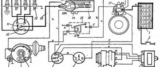
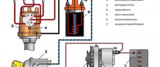
The contactless ignition system (Fig. 1) includes the following devices:
Rice. 1. Diagram of a non-contact ignition system
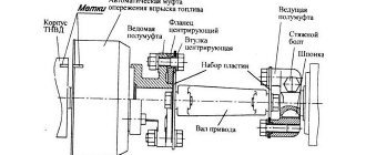
The device of the sensor-distributor is shown in Fig. 2.
The distribution sensor has a housing, a cover, a roller, a sinusoidal voltage sensor, centrifugal and vacuum regulators, as well as an octane corrector.
The centrifugal regulator automatically changes the ignition timing depending on the rotation speed.
The voltage sensor consists of a rotor and a stator.
The rotor is a ring permanent magnet with four-pole cages tightly pressed to it from above and below, rigidly fixed to the sleeve.
A runner is installed on the bushing in the upper part of the rotor.
The sensor stator is a winding enclosed in four-pole plates.
The stator has an insulated stranded lead connected to the sensor lead.
The second terminal of the winding is electrically connected to the housing in the assembled sensor-distributor.
There is a mark on the rotor and an arrow on the stator, which serve to set the initial moment of sparking.
Ignition coil
(Fig. 3)
Winding resistance at temperature (25±10) °C, Ohm:
secondary. 13,000–13,400
Developed secondary voltage maximum, V. 30,000
The coil has a high voltage terminal and two low voltage terminals:
– terminal K – for connection with terminal K of additional resistance;
– unmarked output – with output K3 of the switch.
Additional resistance
(Fig. 3)
The value of active resistance between terminals “+” and “C” is (0.71±0.05) Ohm, between terminals “C” and “K” – (0.52±0.05) Ohm.
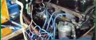
Many UAZ owners know about the vagaries of classic ignition, which sometimes presents unpleasant moments. And often craftsmen find ways to modernize a problematic unit or an entire system. And one such method of improving the launch system with your own hands will be discussed in this publication.
In the photo, UAZ 31514 is a reliable all-terrain vehicle for many purposes.
Contactless ignition system for UAZ without CVT, with switch 131 3734
Contactless ignition system on a UAZ without a variator, with a switch 131 3734, which itself can limit the current through the coil: You can simply install the 131st switch, throw out the variator, connect it according to the diagram and not touch anything else. Or you can go further, throw out the standard harness, the EPH system and install a switch under the hood in place of the variator. Then your harness going into the cabin will disappear and reliability will increase significantly.
Note on the first two non-contact ignition schemes. According to GOST, the coil terminals are marked:
- “K” - output of the end of the low voltage winding
- “B+” or “+12v” - combined output of the windings.
As you can see in the diagram, native to UAZ, the coil itself is drawn exactly like this, a combined output to the “short circuit” of the switch. Indeed, it is strange that the plus is supplied to “K” and not to “+12v”, but the designers know better. I tried connecting it the other way around and didn't notice any difference. But it’s still better to do it according to the instructions. What if there is some secret meaning in this that we just don’t understand?
terms of Use
Experienced car enthusiasts assessed the car modification differently. In comparison with its predecessor - UAZ 469, the new “three hundred and fifteenth”:
- Became more comfortable, which was facilitated by alterations to the interior and chassis;
- It lost its off-road qualities because it received gearboxes with changed gear ratios.
In practice this was expressed as follows:
- When used in off-road conditions, the old 469 easily overcame mud thanks to its “military bridges”;
- The new UAZ could be “buried” in swampy areas due to the installation of “civilian” bridges;
- The maximum speed of “469” did not exceed 90-100 km/h on the highway;
- The new UAZ 31514 accelerates to 120-130 km/h.
Conclusions: the appearance of the “civilian” version allowed the Ulyanovsk Automobile Plant to maintain its leadership among domestic SUVs. UAZ cars are still popular vehicles for many municipal and emergency services.
To ensure the functionality of all electrical devices on any car, an electrical circuit is used. In this article we will talk about the legendary domestically produced cars - UAZ. What is the electrical circuit of the UAZ Bukhanka car, what are its features - read about it below.
[Hide]
Diagnostics of a contactless ignition circuit with a Hall sensor
First of all, turn on the ignition and use a tester to check the presence of +12 volts at the “+B” terminal of the coil. If there is no power, we look for why, this is not a malfunction of the ignition, but of the wiring. If you just need to get there, then we throw the “snot” from the battery positive to “+B” and start. If there is power, then do the following: Check the coil:
- 1. We measure the resistance between “B+” and “K”, it should be 0.4 - 0.8 Ohm, depending on the type of coil.
- 2. We measure the resistance between “B+” and the high-voltage terminal, it should be from 4.5 to 12 kOhm, depending on the type of coil.
- 3. We measure the resistance between any of the contacts and ground - there should be no resistance.
If there are significant deviations in the parameters, a break or short circuit, the coil is dead.
Historical reference
Traditionally, the UAZ 469 was produced in two versions:
- Cargo-passenger version – 7 seats and 100 kg of luggage;
- Commander version - 2 seats for passengers and 600 kg of luggage.
For reference: regardless of the version, the UAZ 469 can tow a trailer with a total weight of 850 kg.
The price of UAZ 469 for the army was the lowest due to large orders
Industry standard 1945
According to the old vehicle classification system, in force since 1945, the UAZ 469 was produced under this name, using an alphanumeric name:
- The letter abbreviation UAZ stood for Ulyanovsk Automobile Plant;
- 469 is a serial factory index assigned by the enterprise itself to its models and developments.
For reference: according to the industry standard of 1945, each automobile plant was assigned a specific numbering. For MZMA, which produced Moskvich 408 and 412, these are numbers from 400 to 449, for the Ulyanovsk Automobile Plant these are numbers from 450 to 484, etc.
Read also the article “Wiring VAZ 21103: features of a 16-valve valve.”
1966 Industry Standard
Although at the time of the release of the UAZ 469 (1972) a new industry classification system was adopted (industry standard OH 025270-66), the car plant continued to use the name according to the old standard.
However, in 1985, the automaker was forced to change its name in accordance with current requirements:
- the car was assigned a four-digit number - 3151;
- According to the new system, the car can be called in the documentation as UAZ 3151.
UAZ 469 wiring: electrical diagram for UAZ-3151
For reference: industry standard OH 025270-66 prescribes determining the type of vehicle by engine displacement, length and weight. The first digit indicates the class of the car, the second – the type (truck or passenger car), the third and fourth – the factory model index.
The car plant named all further modifications and new models in accordance with current standards. In particular, the UAZ Patriot, which appeared in 2005, according to the industry classification, received the “correct” designation - UAZ-3163. For greater identification, the factory instructions contained both names.
Black and white wiring diagram of UAZ Patriot
For reference: the automaker, even in the promotional video for the Patriot model, makes every possible reference to the legendary “ancestor” - the UAZ 469. This model really turned out to be capable of effectively coping with domestic off-road conditions.
Checking the Hall sensor and switch
- Turning on the ignition, remove the connector from the Hall sensor and measure the voltage between the outer contacts, there should be 12 volts, this is the power supply for the sensor. If there is power, go to the next step by plugging the connector back in, if not, change the switch, it’s dead.
- We set the tester to measure voltage (a tester with an arrow is better, it will deviate jerkily, digital testers sometimes “slow down”) and connect it, without disconnecting the switch and piercing the insulation with the ends of the probes, to contacts 6 and 3 of the switch. We turn with the starter. The tester should show pulses from 0.4 volts to no less than 9 volts. There are impulses - we change the switch. There are no pulses - we change the Hall sensor.
If someone’s octane corrector plate, which secures the distributor, has burst, then to repair it, you need to cut an M6 thread and rubber rings for sealing.
Generator wiring diagram
Elements of the G-250E1 alternator circuit, used on early machines:
- Brush.
- Contact ring.
- Excitation winding.
- Diode rectifier bridge.
- Heat sink plate.
- Stator windings.
Generator G250 with a power of 350 W
Generators with improved parameters installed on later UAZ 3151 vehicles are connected in a similar way.
Ignition contact diagram with variator and Moskvich coil B-115
An ancient contact circuit for the ignition of the oldest UAZs, with a Moskvich B-115 coil and an additional resistance installed directly on the coil. The additional resistance terminal “to the starter relay” in some wiring options is connected to additional contacts on the ignition switch, and not to the starter relay. It also happens that it is connected not to the intermediate relay, but to the starter solenoid relay to a special terminal. Be careful. The meaning of this design solution is that at the moment the starter turns, “+12V” is supplied to the coil bypassing the additional resistance, which compensates for the voltage drop in the on-board network when the starter is operating and makes it easier to start the engine; in simple terms, the spark does not weaken.
Features of electrical equipment
For designers, a more difficult process in those years was to find high-quality components to equip the ignition and lighting systems.
This can be clearly seen from the filling of the cabin:
- vehicle system controls;
- control devices.
External lighting
Everything that could be obtained was used to ensure uninterrupted supplies to the factory conveyor.
How is the electrical circuit of the UAZ 31514 different? The car received a completely different ignition system from the previous one; it became contactless. At the same time, reliability remained at the highest level, just like that of the UAZ 2206. The choice of this particular achievement of the modern automotive industry is associated not only with the electrical wiring, but also with the quality of the overall assembly. All models, including UAZ 390945 and others, amaze with their reliability, durability, strength, and ease of use.
1 — front lamp; 2 - headlight; 3 — sound signal; 4 - fuse; 5 — side direction indicator; 6 — additional resistance; 7 — heater switch; 8 — heater fan electric motor; 9 — engine compartment lighting; 10 - generator; 11 — turn signal and hazard warning relay; 12 — spark plugs; 13 — heater resistance (resistor); 14 — starter relay; 15 — ignition coil; 16 — sensor-distributor; 17 - switch; 18 — battery; 19 — ground switch; 20 — electric washer; 21 — emergency vibrator; 22 — fuse block; 23 — oil pressure indicator sensor; 24 — coolant temperature sensor; 25 — coolant overheat sensor; 26 — emergency oil pressure sensor; 27 — sensor of insufficient brake fluid level; 28 — starter; 29 — headlight relay; 30 — portable lamp socket; 31 — parking brake warning switch; 32 — brake signal switch; 33 — speedometer; 34 — indicator of insufficient brake fluid level; 35 — parking brake activation indicator; 36 — turn signal indicator; 37 — indicator for turning on the main beam of headlights; 38 — carburetor microswitch; 39 — windshield wiper; 40 — block of the EPHH system; 41 — windshield wiper relay; 42 — electromagnetic valve of the EPHH system; 43 — warning lamp for emergency oil pressure; 44 - warning lamp for coolant overheating; 45 - central light switch; 46 — alarm switch; 47 — fuel level indicator; 48 — coolant temperature indicator; 49 — oil pressure indicator; 50 - voltmeter; 51 — interior lamp; 52 — interior lamp switch; 53 — right steering column switch; 54 — horn switch; 55 — fuel level sensor; 56 — left steering column switch; 57 — fuel level sensor switch; 58 — cigarette lighter*; 59 — rear fog lamp switch; 60 - thermal (bimetallic) fuse; 61 — ignition switch; 62 — ignition relay; 63 — reverse light switch; 64 — rear light; 65 — additional brake light*; 66 — reversing light; 67 — rear fog lamp; 68 — license plate light; 69 — trailer socket*. * Installed on car parts.
The presented model is more reliable, for example, 390994, the injector of which causes many problems for customers and requires close attention to temperature sensors. The electrical equipment of the UAZ 469 or UAZ 3303 had a simpler system, there were no such problems, and the later electrical circuit of the UAZ 2206 was made much simpler, which did not in any way affect reliability and quality.
VAZ ignition contact diagram for UAZ
Scheme with a contact distributor and a coil from a Zhiguli. Coil - for contact ignition system!
WHEN INSTALLING, DO NOT TRUST THE COLORS OF THE WIRE IN THE HARNESSES!!! Call them a tester. The strands are knitted haphazardly and the colors often do not match the correct ones!
The operating order of the cylinders is 1-2-4-3, the slider rotates COUNTERclockwise, if you look at the distributor from above, 1 terminal of the distributor is marked with a number on its cover. This means that the 1st terminal of the distributor is connected to the spark plugs of the 1st cylinder, the 2nd terminal from the spark plugs of the 2nd cylinder, the 3rd terminal of the distributor from the spark plugs of the 4th cylinder and the 4th terminal of the distributor is connected to the spark plugs of the 3rd cylinder. The countdown starts from the 1st output of the distributor counterclockwise, in the direction of the slider.
A guide to replacing a distributor with an oil pump drive
Before installing a new distributor with a drive, you need to weigh your strengths, since it is not recommended to make mistakes when performing work.
So, how to replace and install the distributor:
- Turn off the ignition and remove the distributor cover; the tips and high-voltage cables are connected to it.
- Then you need to disconnect the wire connected to the switch from the distribution mechanism. You also need to disconnect the pipe connected to the vacuum regulator.
- Taking a 13mm wrench, unscrew the two nuts securing the device and remove the mechanism along with the oil pump drive from the power unit.
- After completing these steps, you will be able to see the gasket located under the drive. If as a result of these actions the position of the crankshaft has not changed, then simply install a new mechanism, making sure that the slider is located opposite the mark. All actions are performed in reverse order. When the installation is completed, the advance angle is adjusted.
- If, as a result, the location of the shaft has changed, then before installation it is necessary to move the piston of cylinder 1 to top dead center. You need to ensure that the marks on the pulley align with the pointer on the motor itself.