Payment for goods and downloading of the book in electronic form (PDF format) is made on the website.
To do this, you need to find the book you are interested in and click on the “Buy” button. The price of the book is indicated on the button.
For convenience, the price on the website for residents of Russia, Belarus and Kazakhstan is presented in rubles.
For residents of Ukraine in hryvnias, and for all other countries - dollars.
After clicking on the “BUY” button, a payment window will open where you can select a payment system with which you can pay for the selected book using any bank card (Visa, MasterCard, MIR, etc.)
When you click on the “Pay by bank card” button, the Portmone payment system will open, which is the easiest way to make a payment.
In addition, the website offers four payment systems for payment:
- Yandex (payment from any bank cards, Yandex Money account, QIWI Wallet, terminals, etc.);
- Portmone (payment from any bank cards, Portmone account);
- PayPal (payment from any bank cards, PayPal account);
- WebMoney (payment from any bank cards, payment from WebMoney wallets).
Payment via Yandex Cashier
After selecting payment via Yandex, the Yandex Cashier payment system will launch, where you need to select a convenient payment method (bank card, QIWI, Yandex Money account, etc.)
After specifying payment details and confirming payment, payment for the goods will occur.
If you have a bank card in a currency other than the ruble, then the money will be debited from the card at the rate of the Central Bank of Russia at the time of the purchase.
This payment method is optimal for residents of Russia, Kazakhstan and Belarus.
Official website of the Yandex Kassa payment system https://kassa.yandex.ru
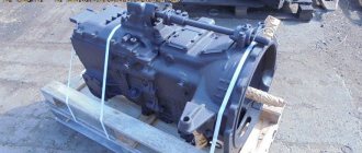
REPLACING THE INTERMEDIATE AXLE GEARBOX
Removing the intermediate axle gearbox
To remove the gearbox, unscrew the magnetic drain plug of the intermediate axle housing and drain the oil, then screw the plug back in. Unscrew the 1/4″ drain plug KG of the center differential housing and drain the oil; screw the plug back in.
Unscrew the nuts of the bolts securing the yoke flange of the intermediate axle driveshaft to the center differential flange, remove the bolts from the flange holes and move the driveshaft to the side. Unscrew the nuts of the bolts securing the yoke flange of the rear axle propeller shaft to the rear axle rear shaft flange, remove the bolts and move the propeller shaft to the side. Unscrew the nuts of the upper front reaction rod bracket, remove the spring washers, expansion bushings and move the rod up. Disconnect the electrical wires for the center differential lock release and pull them out of the wire mounting bracket. Unscrew the union nut of the flexible hose of the center differential lock mechanism drive and disconnect it. Unscrew the nuts of the gearbox mounting studs, remove the spring washers, the elbow of the tees for air distribution to the brake chambers of the intermediate bridge and the brackets for fastening the horizontal rod of the brake force regulator assembled with the rod.
Unscrew the nuts of the studs securing the right axle shaft of the intermediate bridge and remove the spring washers, screw in the release bolts and separate the axle shaft flange from the hub, remove the expansion bushings and unscrew the bolts, remove the axle shaft from the axle housing and remove the axle shaft gasket. Do the same for the left axle shaft.
Unscrew the filler plug of the intermediate axle gearbox and screw an eye bolt with a tapered thread into this hole. Remove the section of the body platform located above the gearbox. Bring the crane beam, put the grip on the eye bolt; lift the gearbox and place it on the trolley; remove the grip and move the crane beam to the side. Remove the eye bolt and screw the plug into place.
Installation of the intermediate axle gearbox
To install the gearbox, unscrew the filler plug of the intermediate axle gearbox and screw in the eyebolt. Move the crane beam and put the grip on the eye bolt, lift the gearbox from the trolley and lower it onto the intermediate bridge to the level of the connector. Apply a thin layer of sealant to the gearbox housing gasket (use UN-25 paste as a sealant) and place the gasket on the gearbox mounting studs. Align the gearbox holes with the intermediate axle housing studs and install the gearbox; remove the boom crane grip from the eye bolt and move the beam crane to the side. Place spring washers on the gearbox mounting studs, the bracket for fastening the horizontal rod of the brake force regulator assembled with the rod, and the air outlet elbow to the brake chambers of the intermediate axle; tighten the nuts and tighten them. Lift the rear axle driveshaft and attach it to the intermediate axle rear shaft flange, aligning the bolts; Place spring washers on the bolts, screw on the nuts and tighten them. Lift the driveshaft of the intermediate axle and attach it to the center differential flange, aligning the holes in the flanges; insert bolts into the holes; Place spring washers on the bolts, screw on the nuts and tighten them. Align the upper front reaction rod bracket holes with the studs and install the bracket; put the expansion bushings on the studs, spring washers, screw on the nuts and tighten them (tightening torque 177... 216 N m (18... 22 kgf.m). Connect the electrical wires to the center differential lock sensor and secure them in the bracket. Connect the flexible hose to the locking mechanism center differential by screwing in the union nut. Apply a thin layer of sealant to the gasket of the right axle shaft and put it on the axle shaft mounting studs (use UN-25 paste as a sealant). Insert the right axle shaft into the intermediate axle housing; align the splined end of the axle shaft with the splines of the side gear in differential and insert it into the gear, putting the axle shaft flange on the hub studs; place expansion bushings and spring washers on the axle shaft mounting studs; screw on the nuts and tighten them (tightening torque 118... 137 N m (12... 14 kgf.m).
Repeat the same for the left axle shaft.
Remove the eye bolt from the filler hole of the gearbox housing and fill the crankcase with oil. Screw the plug into the filler hole. Remove the plug from the filler hole of the center differential housing. Fill the differential housing with oil. Screw in the plug.
Install the body platform section. Check the operation of the main drive of the intermediate axle with mileage. A slight noise of gears is allowed without howling or metallic knocks. Oil leakage is not allowed.
Payment via Portmone
After selecting payment through Portmone, the payment system will launch, where you need to select the payment method: bank card or Portmone account.
The price in the Portmone payment system is converted into dollars at the exchange rate of the Central Bank of the country where you are located.
If you have a bank card in a currency other than the dollar, then the money will be debited from the card at the rate of the Central Bank of your country at the time of the purchase.
After specifying payment details and confirming payment, payment for the goods will occur.
Official website of the Portmone payment system https://www.portmone.com
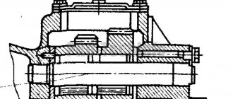
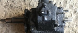
Design and principle of operation
KamAZ trucks are equipped with single- and two-cylinder piston-type units, and rarely with membrane-type units.
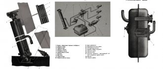
The compressor device is presented as follows:
- Connecting rod.
- Piston.
- Cylinder with spacer.
- Rings:
- sealing;
- oil scraper;
- compression
- Sliding bearings.
- Carter.
- Crankshaft,
- Drive gear.
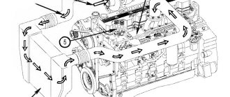
The single-stage compression mechanism is located on the front of the engine flywheel housing. The piston is made of aluminum and has a floating pin secured by thrust rings. Atmospheric air enters the cylinder from the intake manifold of the power plant, which is forced out into the pneumatic system through the discharge valve in the cylinder head.
The liquid is supplied from the engine cooling system and reduces the heating of the cylinder head. Oil flows through the pipelines to the rubbing parts, which lubricates the rear end of the compressor crankshaft and the connecting rod-piston group by splashing.
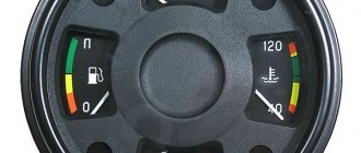
As soon as the pressure of the pneumatic system reaches 0.8-2 MPa, the pressure regulator is activated and stops the air supply. When the indicator drops to 50 kPa, it closes the outlet, and the compressor pumps air into the system again.
The design and principle of operation are similar to autocompressors for passenger cars, with the only difference being that KamAZ trucks have double protection against short circuits and overheating.
Payment via PayPal
After selecting payment via PayPal, the PayPal payment system will launch, where you need to select the payment method: bank card or PayPal account.
If you already have a PayPal account, then you need to log into it and make a payment.
If you do not have a PayPal account and you want to pay using a bank card via PayPal, you need to click on the “Create an Account” button - shown with an arrow in the picture.
PayPal will then prompt you to select your country and provide your credit card information.
After specifying the information required to make the payment, you must click on the “Pay Now” button.
Official website of the PayPal payment system https://www.paypal.com
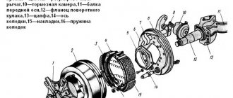
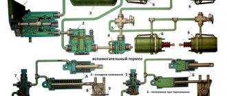
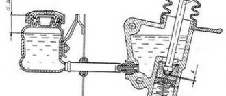
How to adjust an energy accumulator on a KAMAZ
Having relaxed the clamp, release the spring. In the case when, while supplying air inside the parking brake chamber, it is not possible to sink the rod, it is necessary to sacrifice the glass. To do this, drill 2 holes 6 cm from the middle part. Using the same clamp or press, recess the rod to its full depth, then insert restrictive pins into the drilled holes (bolts of at least 8 mm in size can be used) and prevent the piston from returning on its own. After removing the locking ring in the rod, it is possible to get rid of the restrictive pins; this also happens with the help of a press or clamp. Then the glass is removed.
Payment via WebMoney
After selecting payment via WebMoney, the payment system will launch, where you need to select the payment method: bank card or WebMoney wallet.
If you already have a WebMoney wallet, then you need to log into it and make a payment.
If you do not have a WebMoney wallet and you want to pay in another way, you need to select any of the methods that WebMoney offers and make the payment
After specifying payment details and confirming payment, payment for the goods will occur.
Official website of the WebMoney payment system https://www.webmoney.ru/
Do-it-yourself maintenance of the KamAZ balancer - we cover the issue
KAMAZ vehicles have a rear suspension equipped with a balancing device, which is pressed into a bracket, which is part of the balancer axis, acting as a coupler. The springs are equipped with removable supports. The reaction arms located below, which increase repairability, are also removable. Mounting plates are used to secure the supports to prevent them from moving. To limit the movement of the axles in the downward direction, the spring supports are equipped with axle roll limiters.
Repair of KAMAZ balancers, including repair and restoration of the KAMAZ balancer axis, involves checking, first of all, the condition of springs, torque rods, balancer shoes, and stepladders. When the shoe bushings related to the balancing device are worn out, when the level of wear exceeds the permissible level, the axles should be ground to remove signs of wear and repair bushings with a reduced internal diameter should be installed.
Downloading a book
After successfully completing the payment (by any method) and returning to the KrutilVertel store from the payment system website, you will be taken to the successful payment page:
On this page you need to indicate your e-mail, where access to download the book will be sent.
If you are already registered on our website, then simply follow the link to your personal account.
The book you purchased will be in your personal account, from where you can always download it.
Please note that after making the payment, you need to return back from the payment system website to the KrutilVertel website.
If for some reason you did not return back to the site and closed the payment system tab with a message about the successful completion of the payment, please let us know - we will send you a letter indicating access to download the book.
Selecting units
The market for spare parts for trucks offers quite a large selection. You can select devices with different parameters, units for trailers with SAF, ROR, BPW axles. There is also a large selection of energy accumulators for semi-trailers with disc and drum brakes. The energy accumulator and brake chambers can be installed both on imported models and on domestic KamAZ and MAZ vehicles, although this is not always worth doing, reviews say. The car must be equipped only with spare parts intended for a specific model. Otherwise, the high-quality and stable operation of such a mechanism cannot be guaranteed.
Problems when paying with bank cards
Sometimes difficulties may arise when paying with Visa/MasterCard bank cards. The most common of them:
- There is a restriction on the card for paying for online purchases
- A plastic card is not intended for making payments online.
- The plastic card is not activated for making payments online.
- There are not enough funds on the plastic card.
In order to solve these problems, you need to call or write to the technical support of the bank where you are served. Bank specialists will help you resolve them and make payments.
That's basically it. The entire process of paying for a book in PDF format on car repair on our website takes 1-2 minutes.
If you still have any questions, you can ask them using the feedback form, or write us an email at [email protected]
Malfunctions
During operation, it is necessary to monitor the technical condition of the mechanism, lubrication and the flow of coolant. It is recommended to use only the oil that is specified in the power plant data sheet. Lubrication with contaminated oil is prohibited.
The compressor does not require daily or special technical inspections, but the drive and fastening reliability are checked periodically once every 8-10 thousand km.
During operation, breakdowns of unit parts may occur; they are repaired immediately. Those that are faulty must be replaced.
The main malfunctions of a truck compressor are divided into 2 types:
- piston group;
- electrical equipment.
The most common defects are:
- Wear of the piston group and violation of valve tightness. Duration of filling the pneumatic system at a crankshaft rotation speed of 2200 rpm. exceeds the time established by the technical specifications (8 minutes). The compressor does not pump up a pressure of 7-7.5 kgf/cm². Piston wear causes oil mist to be drawn from the compressor crankcase into the cylinders.
- The system supercharger does not start. Associated with a lack of voltage in the network, a leaking check valve and improper starting.
- The compressor pumps poorly and does not gain speed. One of the reasons is clogged filters.
- Knocks in the cylinder-piston mechanism. Associated with breakdowns in the discharge part as a result of friction and wear of metal parts.
- The engine hums and does not rotate. This problem is possible due to the operation of the mains power fuse, overload protection, or poor contact.
- Strong heating of the cylinder. Airflow to the cylinder and crankcase is blocked.
- Performance decreases - the suction air filter is clogged.
- Increased vibration.
Defects of single- and double-cylinder compressor parts
To identify hidden defects in compressor parts and establish its suitability for further operation, defect detection is carried out. As a result of the check, the following parts are rejected:
- with chips;
- deformed (curved);
- with bumps and minor risks;
- with cracks.
If the cylinders are worn in the inner diameter by 0.02 mm or more, they will need to be bored (according to the table below).
In addition to the inner surface of the cylinder, the crankcase is checked for wear, namely the holes for the ball bearings, as well as the plane of contact of the head to the cylinders (the difference should be less than 0.1 mm).
The diameter of the installation hole of the valve of single-cylinder or two-cylinder KamAZ compressors should not exceed 28.9 mm. Compressor discharge valves are subject to heavy load and friction during operation, so minor risks are usually eliminated by grinding in the rubbing surfaces.
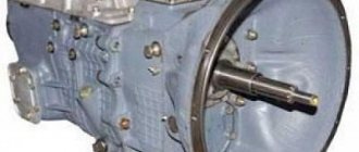
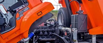
How to remove and disassemble
In order to replace failed elements, it is necessary to remove and disassemble the compressor. It is not difficult to dismantle the necessary component of a KamAZ vehicle (for example, model 65115 or 4308).
- Raise the cab, the unit is located underneath it.
- Unscrew the fastening nuts, remove the head together with the discharge valves, gasket, and springs of the inlet elements.
- Unscrew the 3 tubes using the appropriate wrench.
- Unscrew the drive gears and lift the unit towards the front of the vehicle.
Repair
Many equipment owners perform simple routine repairs of a KamAZ compressor with their own hands. The repair work includes several stages, which are as follows:
- Cleaning parts. The burnt oily liquid inside the cover is removed by sandblasting, the element is polished, and the coolant is removed. Then wipe and polish the working surface of the valve plate.
- Boring and honing of the cylinder. When working, take into account the parameters of the thermal gap. If the inner side of the cylinder is worn more than 0.02 mm, an expansion is made for repair boring. In some cases, sleeves are installed.
- Replacement of crankshaft connecting rod bearings and bushings with ones that are suitable in terms of characteristics and parameters.
- Replacement of pistons equipped with pins and connecting rod rings. During repairs, special attention is paid to the parameters of the cylinder.
- Replacement and repair of gaskets, intake and exhaust valves, seals. The latter must be covered with fasteners.
The equipment is installed on a special stand and tested for performance. When checking, the technician compares the results obtained with the factory parameters of the compressor.
If overheating of the bearings is detected, extraneous knocking of pistons and valves is heard, or the compressor is pumping oil, while the permissible rate of leaking liquid exceeds the required levels, repair work is resumed, but preferably at a service station.
How to install
After replacing parts, the compressor must be installed back. To do this you should:
- Place the connecting rod in a vice, press in the bushing and pin, lubricating it with oil.
- Place the rings and remove the part from the vice.
- Attach the head, seat gaskets, valves, springs.
- Screw in the plugs.
- Press in the crankshaft with oil seals, install thrust rings.
- Install the gear wheel and lock washer.
- Pull the cover with gasket onto the crankcase and secure with bolts.
- Blow with compressed air.
- Press the intake valves and guides into the cylinder block.
- Install the unit head onto the block and tighten with nuts.