Air control devices
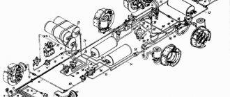
Air controls include a two-piece brake valve, a manual brake valve, a push-button brake valve, trailer brake control valves, a relay valve, a dual-line bypass valve, a quick brake release valve, a release valve, and coupling heads for connecting the tractor air drive to the trailer air drive.
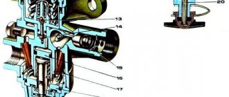
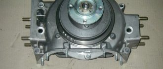
Two-piece brake valve
A two-section brake valve (Fig. 1) is used to control the air supply to the mechanisms of the vehicle’s service brake system and the combined drive of the trailer’s brake mechanisms, serving two circuits. The crane is controlled mechanically using a system of levers and rods from the brake pedal. The crane has two independent sections located in series.
When braking, the force from the brake pedal is transmitted through the elastic element of the valve to a stepped piston, which, moving down, closes the valve outlet, cutting off the output of the brake circuit from the environment. To move the upper piston down, compressed air enters the circuit of the working brake mechanisms of the wheels of the rear bogie. The action of compressed air and the spring of the stepped upper piston from below balances the force applied to the brake pedal.
When the pressure in the outlet to the rear bogie circuit increases, compressed air passes through the channel into the cavity above the accelerating piston and, moving it down, causes the stepped lower piston to move, which first closes the valve outlet, blocking the outlet to the environment, and then opens this valve , ensuring the flow of compressed air through the outlet into the brake chambers of the front wheels.
When the pressure in the output to the front wheels increases, the compressed air, passing under the accelerating piston and the lower stage piston, together with its spring, balances the force acting on the piston from above. Consequently, a pressure corresponding to the force on the brake valve lever is established in the output of the front wheel circuit. Thus, a tracking action is carried out in both sections of the crane depending on the force the driver applies to the brake pedal.
If the circuit of the lower section is damaged, the upper section works as usual, i.e. in this case the operation of the upper section is not affected. If the pressure in the upper section decreases due to damage to its circuit, the force from the brake valve lever through the pin will be transmitted directly to the lower piston pusher. In this case, the lower section, controlled by mechanical action, will retain its functionality.
When braking stops, the elastic element returns to its original position. The lower and upper stepped pistons rise upward under the action of the return springs, and the leads to the drive circuits of the working brake mechanisms are blocked, disconnecting them from the line. Then the outlet windows open, through which communication with the environment occurs.
Manual brake valve
The manual brake valve for controlling the drive of the parking and spare brake systems (Fig. 2) controls pneumatic mechanisms that operate by releasing compressed air. When released, the guide cap and rod occupy the lower position. The rod pushes the exhaust valve down, closing its internal hole, and moves it away from the piston. The outlet to the environment, carried out through the internal hole of the exhaust valve, is closed in this case, and the sub-piston cavity communicates with the supra-piston cavity through the annular slot between the exhaust valve and the piston. Compressed air from the outlet to the receiver through the hole in the piston, into the sub-piston and above-piston cavities enters through the outlet to the energy accumulators through the accelerator valve. The springs of the energy accumulators are compressed, which corresponds to the disengaged state of the brake mechanisms of the wheels of the rear bogie.
Not available:
| № | Part code | Name | Part Information |
| 100-3537129-01 | Protective cover | Quantity for KamAZ 5320 2) KamAZ 53212 3) KamAZ 5410 4) KamAZ 54112 5) KamAZ 5511 6) KamAZ 55102 7) Model 14 Model 15 1 Model 100 Group Brakes Subgroup Brake valves with manual control Part number 129 | Not available |
| 5320-3537118 | Bracket assembly | Quantity for KamAZ 5320 2) KamAZ 53212 3) KamAZ 5410 4) KamAZ 54112 5) KamAZ 5511 6) KamAZ 55102 7) Model 14 Model 15 1 Model 5320 Group Brakes Subgroup Manually operated brake valves Serial part number 118 | Not available |
| 100-3537139 | Nut M26x1.5-6N | Quantity for KamAZ 5320 2) KamAZ 53212 3) KamAZ 5410 4) KamAZ 54112 5) KamAZ 5511 6) KamAZ 55102 7) Model 14 Model 15 1 Model 100 Group Brakes Subgroup Brake valves with manual control Part serial number 139 | Not available |
| 5320-3537117 | Faucet panel | Quantity for KamAZ 5320 2) KamAZ 53212 3) KamAZ 5410 4) KamAZ 54112 5) KamAZ 5511 6) KamAZ 55102 7) Model 14 Model 15 1 Model 5320 Group Brakes Subgroup Manually operated brake valves Serial part number 117 | Not available |
| 1/05164/77 | Spring washer 6 | Quantity for KamAZ 5320 2) KamAZ 53212 3) KamAZ 5410 4) KamAZ 54112 5) KamAZ 5511 6) KamAZ 55102 7) Model 14 Model 15 2 Fastener yes Material other metal materials, i.e. not steel, not brass , not light alloy, not copper Coating special coating | Not available |
| 1/03765/11 | Screw M6-6gx12 | Quantity for KamAZ 5320 2) KamAZ 53212 3) KamAZ 5410 4) KamAZ 54112 5) KamAZ 5511 6) KamAZ 55102 7) Model 14 Model 15 2 Fastener yes Material steel 50 (steel with tensile strength 490-784 ( 50-80) MPa (kg/mm2) Galvanized coating | Not available |
| 100-3537125 | Cap | Quantity for KamAZ 5320 2) KamAZ 53212 3) KamAZ 5410 4) KamAZ 54112 5) KamAZ 5511 6) KamAZ 55102 7) Model 14 Model 15 1 Model 100 Group Brakes Subgroup Brake valves with manual control Part number 125 | Not available |
| 100-3537129 | Protective cover | Quantity for KamAZ 5320 2) KamAZ 53212 3) KamAZ 5410 4) KamAZ 54112 5) KamAZ 5511 6) KamAZ 55102 7) Model 14 Model 15 1 Model 100 Group Brakes Subgroup Brake valves with manual control Part number 129 | Not available |
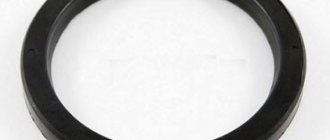
| 307768 | Thrust ring 18.7x21.8x2.2 | Quantity for KamAZ 5320 2) KamAZ 53212 3) KamAZ 5410 4) KamAZ 54112 5) KamAZ 5511 6) KamAZ 55102 7) Model 14 Model 15 2 Coating without coating | Not available |
| 100-3537130 | Sleeve | Quantity for KamAZ 5320 2) KamAZ 53212 3) KamAZ 5410 4) KamAZ 54112 5) KamAZ 5511 6) KamAZ 55102 7) Model 14 Model 15 1 Model 100 Group Brakes Subgroup Brake valves with manual control Part serial number 130 | Not available |
| 100-3537137 | Ring | Quantity for KamAZ 5320 2) KamAZ 53212 3) KamAZ 5410 4) KamAZ 54112 5) KamAZ 5511 6) KamAZ 55102 7) Model 14 Model 15 1 Model 100 Group Brakes Subgroup Brake valves with manual control Part serial number 137 | Not available |
| 100-3537133 | Ring | Quantity for KamAZ 5320 2) KamAZ 53212 3) KamAZ 5410 4) KamAZ 54112 5) KamAZ 5511 6) KamAZ 55102 7) Model 14 Model 15 2 Model 100 Group Brakes Subgroup Brake valves with manual control Part serial number 133 | Not available |
| 489327 | Resistant ring | Quantity for KamAZ 5320 2) KamAZ 53212 3) KamAZ 5410 4) KamAZ 54112 5) KamAZ 5511 6) KamAZ 55102 7) Model 14 Model 15 1 Coating without coating | Not available |
| 100-3537124 | Pusher | Quantity for KamAZ 5320 2) KamAZ 53212 3) KamAZ 5410 4) KamAZ 54112 5) KamAZ 5511 6) KamAZ 55102 7) Model 14 Model 15 1 Model 100 Group Brakes Subgroup Brake valves with manual control Part serial number 124 | Not available |
| 100-3537132 | Spring plate | Quantity for KamAZ 5320 2) KamAZ 53212 3) KamAZ 5410 4) KamAZ 54112 5) KamAZ 5511 6) KamAZ 55102 7) Model 14 Model 15 1 Model 100 Group Brakes Subgroup Brake valves with manual control Part serial number 132 | Not available |
| 100-3537123 | Spring | Quantity for KamAZ 5320 2) KamAZ 53212 3) KamAZ 5410 4) KamAZ 54112 5) KamAZ 5511 6) KamAZ 55102 7) Model 14 Model 15 1 Model 100 Group Brakes Subgroup Brake valves with manual control Part serial number 123 | Not available |
| 100-3512099 | Tablet | Quantity for KamAZ 5320 2) KamAZ 53212 3) KamAZ 5410 4) KamAZ 54112 5) KamAZ 5511 6) KamAZ 55102 7) Model 14 Model 15 1 Model 100 Group Brakes Subgroup Pressure regulator Serial part number 099 | Not available |
| 304183 | Hollow rivet | Quantity for KamAZ 5320 2) KamAZ 53212 3) KamAZ 5410 4) KamAZ 54112 5) KamAZ 5511 6) KamAZ 55102 7) Model 14 Model 15 2 Coating without coating | Not available |
| 100-3537120 | Frame | Quantity for KamAZ 5320 2) KamAZ 53212 3) KamAZ 5410 4) KamAZ 54112 5) KamAZ 5511 6) KamAZ 55102 7) Model 14 Model 15 1 Model 100 Group Brakes Subgroup Manual brake valves Serial part number 120 | Not available |
| 100-3537134 | Valve assembly | Quantity for KamAZ 5320 2) KamAZ 53212 3) KamAZ 5410 4) KamAZ 54112 5) KamAZ 5511 6) KamAZ 55102 7) Model 14 Model 15 1 Model 100 Group Brakes Subgroup Brake valves with manual control Part serial number 134 | Not available |
| 100-3537136 | Spring | Quantity for KamAZ 5320 2) KamAZ 53212 3) KamAZ 5410 4) KamAZ 54112 5) KamAZ 5511 6) KamAZ 55102 7) Model 14 Model 15 1 Model 100 Group Brakes Subgroup Brake valves with manual control Part serial number 136 | Not available |
| 100-3537140 | Guide | Quantity for KamAZ 5320 2) KamAZ 53212 3) KamAZ 5410 4) KamAZ 54112 5) KamAZ 5511 6) KamAZ 55102 7) Model 14 Model 15 1 Model 100 Group Brakes Subgroup Manual brake valves Serial part number 140 | Not available |
| 100-3537142 | Mesh assembly | Quantity for KamAZ 5320 2) KamAZ 53212 3) KamAZ 5410 4) KamAZ 54112 5) KamAZ 5511 6) KamAZ 55102 7) Model 14 Model 15 1 Model 100 Group Brakes Subgroup Brake valves with manual control Part serial number 142 | Not available |
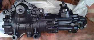
Quick release valve
9.13. Quick release valve.
Quick release of long control lines or brake lines and brake cylinders. The appearance and structure are shown in Figures 240, 241.
In the absence of pressure, the pre-stressed diaphragm (a) lies on pressure relief channel 3 and with its outer edge blocks the passage from outlet 1 to chamber A. Compressed air coming from outlet 1 presses the edge of the diaphragm back and enters through outlet 2 to those connected further brake cylinders.
When the pressure at terminal 1 drops, under the influence of higher pressure in chamber A, the diaphragm (a) bends upward. The further connected brake chambers are fully or partially - depending on the degree of pressure drop at terminal 1 - released through pressure relief channel 3.
Installation recommendations.
The quick release valve should be installed vertically, with bleed port 3 pointing downwards. To secure it, two M8 bolts are used.
Figure 241. Overall dimensions. Terminal designations: 1 - power supply; 2 - energy extraction; 3 - pressure relief channel
What is the quick release valve for?
Trailer release valve WABCO 963 001 05.
0 Release of the brake system, for the movement of trailers in the disengaged state.
When coupling a trailer to a tractor, make sure that the piston (a) is not in the “park” position; if this is the case, the piston must be manually moved to the “drive” position. When connecting the automatic coupling heads, compressed air penetrates through port 1-1 into chamber A. If the piston (c) is still in the “disengage” position, then under the action of the supplied compressed air it is extended to the “movement” position. compressed air penetrates through port 21 to the trailer brake valve and then into the trailer receiver.
From the receiver, compressed air enters chamber B through port 1-2, opens the return valve (b) and, through chamber C and pin 22, penetrates the further connected two-way quick release valve and brakes the chambers of the spring energy accumulators.
In the uncoupled state, pin 1-1 and thus chamber A are disinhibited. To release the service brake system, the piston (c) is pushed in all the way manually using the button provided for this purpose. In this way, the passage from pin 1-1 to pin 21 is blocked and a connection is established between chambers A and pins 1-2.
When the parking brake is applied, the piston(s) extends. The compressed air in chamber C and at outlet 22 exits through bleed hole 3 to the outside. The further connected quick release valve switches and the chambers of the spring energy accumulators are released.
Source