Gearshift rocker: purpose, device, adjustment of the gearbox rocker
Many drivers, while operating a vehicle, sooner or later encounter various vehicle malfunctions. As for the gearbox, in addition to the gearbox itself, with mileage the gearbox rocker often requires attention, especially in the case of a manual transmission.
In practice, the automatic transmission rocker can also malfunction, but it is in the manual transmission that the manual transmission rocker fails noticeably more often. Next, we will talk about what a gearbox linkage is, how the mechanism works, and also what types of gearbox linkage malfunctions are usually found.
Chinese gearboxes for MAZ
The Minsk Automobile Plant has been famous for many years for its high-quality trucks, which are popular not only in Belarus, but also abroad. For example, MAZ cars are one of the most popular cargo vehicles in Russia. Throughout the history of its existence, the company strives to regularly improve its models, not only improving the appearance, but also equipping them with the latest technical details. That is why in 2006, specialists from the Belarusian plant entered into a contract with the Chinese corporation Shaanxi Fast Gear (Shaft Gear). According to this agreement, over 2 years the plant received high-quality gearboxes worth more than $23 million.
Operation errors
The transmission has a complex structural structure.
However, statistics show that most of the causes of breakdowns lie not in the components of the KAMAZ gearbox, but in improper operation. Before driving, the driver must carefully study the instructions to become familiar with the nuances of the operation of a particular model. The most common mistakes are the following:
- not pressing the clutch pedal all the way, which leads to rapid wear of the synchronizers;
- transition from high to low positions at a speed of more than 30 km/h;
- ignoring sequential (in ascending order) switching (transition from speed 5 to speed 1);
- full girth of the gearshift lever (gear shifting of KAMAZ 6520 is allowed only with an open palm);
- moving the selector to find the neutral state, since the car has a built-in lock;
- movement downhill by rolling. Due to passive movement, the oil pump rotates, thereby idling it and the engine. Reduced speeds do not provide optimal lubrication for bearings, which leads to overheating;
- towing all-wheel drive vehicles with a cardan attached to the axle;
- ignoring the neutral position when parking.
Spare parts for Ural, Kraz, MAZ, Kamaz trucks. Engine parts YaMZ-236, YaMZ-238
__________________________________________________________________________
__________________________________________________________________________
YMZ gearbox control drive for Maz-5516, Maz-5440 vehicles
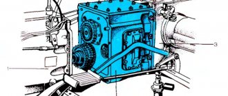
The gearbox drive of the Maz-5516, Maz-5440, 64229, Maz-54323, 54329 and YaMZ-239 vehicles is shown in Figure 4. During operation, if necessary, the following adjustments to the gearbox drive are made: - adjusting the position of the lever in the longitudinal direction; — adjusting the position of the lever in the transverse direction; — adjustment of the locking device of the telescopic drive elements. The procedure for adjusting the control of the YaMZ-239 gearbox of Maz-5516, Maz-5440, 64229, Maz-54323, 54329 vehicles is as follows: - set lever 2 to the neutral position; — by longitudinally moving the plate 16 with the bolts 17 released, set the angle a of the lever 1; — by changing the length of rod 3, set the angle. If the travel of the plate 16 or the adjustment range of the rod 3 is insufficient, loosen the bolts 5, move or rotate the rod 6 relative to the shank 4, tighten the bolts 5 and repeat the adjustment of angles a, b, as indicated above. Angle a should be 80°, angle b should be 90°. Adjust the locking device of the telescopic elements of the YaMZ-239 gearbox of Maz-5516, Maz-5440, 64229, Maz-54323, 54329 vehicles with the cab raised as follows: - unpin pin 8 and disconnect rod 6 from fork 9 of the gearbox drive lever; — loosen locknut 13 and unscrew shank 14 until the thread stops; — push the internal rod 6 until the protrusions of the earring 12 stop into the grooves of the tip 15; — holding the mechanism in a compressed state, screw the shank until the mechanism is locked by bushing K) under the influence of spring 11: — tighten locknut 13, check the smooth operation of the locking mechanism. When the mechanism is locked, axial and angular play should be minimal. In the unlocked position, bushing 10 is shifted to the left. The movement of the extension rod must be smooth, without jamming, and the locking mechanism must ensure clear fixation of the extension rod in its original position. When connecting rod 6 to fork 9, the hole in the shackle for pin 8 should be located above the longitudinal axis of rod 6. Adjust the drive when the engine is not running. When the cab is raised, oil under pressure from the cab lift pump is supplied through hose 7 to the cylinder of the locking device and mechanism 6 is unlocked. After lowering the cab, to securely fix the telescopic mechanism 6 in the locked position, it is necessary to move the gear shift lever 1 forward along the vehicle in a motion similar to turning it on transfers. In this case, the mechanism is blocked and is then ready for work. Gearshift diagram of the Maz-5516, Maz-5440, 64229, Maz-54323, 54329 and YaMZ-239 vehicles, see Figure 5.
Fig.4. Control drive for the YaMZ gearbox of Maz-5516, 64229, Maz-54323, 54329 vehicles 1 - lever; 2 — lever; 3.4- traction; 5.17- bolt; 6 — traction (telescopic mechanism); 7 - hose; 8 - finger; 9 - fork; 10 - bushing; 11 - spring; 12 — earring; 13 - lock nut; 14 - shank; 15 — tip; 16 - plate; 18 — switch Drive for controlling the gearbox of Maz-5516, Maz-5440, 64229, Maz-54323, 54329 vehicles with a MAN engine When controlling the gearbox of Maz-5516, Maz-5440, 64229, Maz-54323, 54329 vehicles, be guided by the following: — The main gearbox and range control are controlled using the gearbox lever according to the diagram shown in Figure 19 (ZF gearbox). — The transition from the slow range of the range to the fast one is carried out by moving the lever in the neutral position away from you, overcoming the force of the lock, from the fast range to the slow one - in the reverse order. — The divider is controlled by a flag on the gearshift lever handle. The transition from the slow range (L) to the fast range (S) and back is carried out by pressing the clutch pedal all the way after moving the flag to the appropriate position. Shifting is possible without switching off the gear in the main gearbox. Adjusting the gearbox control drive of Maz-5516, Maz-5440, 64229, Maz-54323, 54329 vehicles During operation, if necessary, the following adjustments are made to the gearbox drive of Maz-5516, Maz-5440, 64229, Maz-54323, 54329 vehicles for MAN engines: — adjustment of the lever position in the longitudinal direction; — adjusting the position of the lever in the transverse direction; — adjustment of the locking device of the telescopic drive elements. Adjustment of the position of lever 1 (Figure 7) in the longitudinal and transverse directions is carried out by moving and rotating the rod 5 in the shank 6 with the bolts 7 released. In this case, the angle a should be 85°, the angle e=90°. Angle a can also be adjusted by moving plate 3 with bolts 2 loosened.
Fig.5. Gear shift diagram for the gearboxes of Maz-5516, Maz-5440, 64229, Maz-54323, 54329, YaMZ-239 M vehicles - slow range; B - fast range.
Fig.6. Gear shift diagram for the ZF gearbox of the Maz-5516, Maz-5440, 64229, Maz-54323, 54329 L vehicles - slow range; S - fast range.
Fig.7. Gearbox control drive for Maz-5516, Maz-64229, Maz-54323, 54329 cars 1 - lever; 2, 7 - bolt; 3 - plate; 4 - hose; 5 — intermediate mechanism; 6 - shank; 8 - growl The gearbox drive of Maz-5440 cars is shown in Figure 8. The main gearbox is switched using lever 1 of the remote control mechanism. The additional box is controlled by range switch 18 located on gear lever 1. When the range switch is in the lower position, the fast range in the additional box is activated, and when it is in the upper position, the slow range is activated. During operation, if necessary, the following adjustments are made to the gearbox of Maz-5440 vehicles: - adjusting the angle of inclination of lever 1 in the longitudinal direction; — adjusting the angle of inclination of lever 1 in the transverse direction; — adjustment of the locking device of the telescopic mechanism. To adjust the angle of inclination of the lever in the longitudinal direction, you should: - set lever 2 to the neutral position by tightening the neutral position lock on the switching mechanism 20 (for the YaMZ gearbox - 238M). Check the neutral position of the gearbox of the Maz-5440 vehicles by moving the lever shaft 2 in the axial direction by pressing it with your hand. In this case, the roller should move by 30 - 35 mm; — loosen the tightening of bolts 17 and by longitudinally moving plate 16 set the angle “a” to 90 degrees; — if the plate 16 moves insufficiently, loosen the bolts 5, move the rod 6 relative to the shank 4, tighten the bolts 5 and repeat the adjustment of the angle “a” by moving the plate 16. Adjustment of the lever 1 in the transverse direction is carried out by changing the length of the transverse rod 3 by disconnecting one of the tips and unscrewing nuts for its fastening and subsequent adjustment of the length so that lever 1 takes a vertical position. After adjustment, return the neutral position lock to its original position (for the YaMZ-238M gearbox). Adjustment of the locking device of the telescopic gearbox mechanism of Maz-5440 vehicles should be done as follows: - unscrew the pin, unscrew the nut, remove the pin and disconnect rod 6 from fork 9 of the gear shift lever; — loosen locknut 13 and unscrew shank 14 until the thread stops; — push the internal rod 6 until the protrusions of the earring stop into the grooves of the tip 15; — holding the mechanism in a compressed state, screw in the shank 14 until the mechanism is locked by the sleeve 10 under the influence of the spring 11; — tighten locknut 13, check the smooth operation of the locking mechanism. When the mechanism is locked, axial and angular play should be minimal. In the unlocked position (sleeve 10 is shifted to the right), the internal rod should be pushed out by the return spring by 35 - 50 mm. Further movement of the extension rod must be smooth, without jamming, and the locking mechanism must ensure clear fixation of the rod extension in its original position. The drive rod and its telescopic components should not be bent or bent. Adjust the gearbox drive when the engine is not running.
Fig.8. Gearbox control drive for MAZ-5440 vehicles 1.2-lever; 3, 4, 6 — thrust; 5, 7, 17 — bolt; 8 - finger; 10 - bushing; 11 - spring; 12 — earring; 13 - nut; 14 - shank; 15 — tip; 16 - plate; 18 — switch 19 — ball; 20 - switching mechanisms.
_________________________________________________________________________
_________________________________________________________________________
_________________________________________________________________________
- Cardan shafts and power take-off Ural-4320
- Transmission gearbox Ural-4320
- Bridges Ural-4320
- Transfer case Ural-4320
- Steering Ural-4320
- Truck cranes and cranes based on trucks
_________________________________________________________________________
_________________________________________________________________________
- Cylinder block and cylinder head YaMZ-236 HE2, YaMZ-236 BE2
- Checking and adjusting YaMZ-236
- Power system and lubrication system YaMZ-236
- Driven and driven clutch discs YaMZ-236, 238
- Cooling and lubrication systems YaMZ-238
- Fuel injection pump YaMZ-238
_________________________________________________________________________
- Kamaz diesel engine
- Repair and adjustment of Kamaz power steering
- Kamaz-152 gearbox with divider
- Gearbox parts for Kamaz-5320 gearbox
- Kamaz transfer case and driveshafts
- Kamaz gearbox repair
- Clutch KamAZ-5320
- Construction of Kamaz-4310 drive axles
- Power steering MAZ-5551, 5549, 5335, 5336, 5337
- Front axle and steering rods MAZ-5551, 5549, 5335, 5336, 5337
- Clutch adjustment MAZ-5551, 5549, 5335, 5336, 5337
- Adjustment and repair of gearboxes MAZ-5551, 5549, 5335, 5336, 5337
- Repair and maintenance of the rear axle MAZ-5551, 5549, 5335, 5336, 5337
- Front axle parts and steering rods MAZ-5516, 5440
- Steering Maz-5516, 5440
- Details of driving axles Maz-5516, 5440
- Clutch device ZIL-130
- Repair of ZIL-130 gearbox
- Repair of rear axle ZIL-130
- Basic parts of the ZIL-130 engine
- Transfer case and power take-off ZIL-131
- Drive axles ZIL-131
- Steering ZIL-131
- Maintenance of ZIL-645 engine parts
Signs of gearbox wear
The driver must pay attention to possible failure of vehicle components, including knowing the characteristic signs of wear on the gearbox linkage in order to take timely action to replace it. Despite the fact that the mechanism is quite reliable, you should be aware of the following “symptoms” of its imminent breakdown:
- Increased play at the gearshift knob. This can be noticeable both when the handle is in neutral and in one of the gears;
- Difficulty shifting gears. For example, one or more gears are difficult to “stick”, or maybe a crunching noise occurs when the lever moves in their direction;
- It feels like changing gears has become more difficult, as if the lever has become much heavier;
- Gears are engaged incorrectly, for example, instead of fifth, third is engaged or vice versa.
Transmission options for heavy-duty vehicles
The 8-speed MAZ gearbox is typical for vehicles that have a high load capacity.
9-speed versions are installed not only on powerful trucks, but also on ordinary cars.
5-speed gearboxes are present on the MAZ-500 with the YaMZ-236 diesel engine.
5 speed gearbox
16-speed versions are found on dump trucks and KamAZ vehicles. The weight of the box exceeds 250 kg. The ZF16S gearbox has an adapter plate that communicates with the engine and gearbox.
The listed versions are distinguished by high reliability and long-term operating capability.
Those who want to enjoy a full ride both in urban conditions and on rough terrain decide to purchase a MAZ car with a ZF gearbox. This type of gearbox is often found on snow removal equipment.
Why do you need a gearbox slide?
In fact, most often the gearbox is in good condition, but the rocker may fail.
You can replace the unit with a new one, or you can get by with proper adjustment of the rocker. Adjusting this element will help troubleshoot problems and make sure that the problem is related specifically to the gearbox linkage. It happens that a car owner simply begins to change one component after another without understanding the problem, wasting money and time to no avail.
The gearbox itself is designed to prevent gears from switching spontaneously . It happens that due to incorrect or erroneous adjustments, the entire transmission system begins to work incorrectly and may even fail. Therefore, you need to be able to adjust the gearbox rocker with your own hands, especially since this procedure is not complicated.
When does the rocker need adjustment?
Gear shift mechanism.
The procedure for adjusting the gearbox linkage is recommended in the following cases:
- After the transmission on the car has been replaced or removed.
- When loosening the fixing clamps.
- If the cardan was changed.
- If the link starts to rotate on its hinge.
Question answer
During the flight, the first gear at the YaMZ-236 gearbox began to jump out. They promised me a secondary shaft and Saturday was just approaching. All that’s left to do is remove, disassemble and sort through the box.
Arriving at the parking lot on the weekend, I began to remove the box. Due to the fact that work forced me to do this at least twice a year, I was not very upset. The gearbox was dismantled, pulled out from under the car and disassembled.
While troubleshooting the gearbox, it immediately caught my eye that the teeth on the intermediate shaft were mostly crumbled, and in some places were completely absent at the point of contact with the large first gear gear. The first gear gear on the input shaft itself did not require replacement. In a word, disassembling the gearbox only confirmed my guesses - I had to go after the shaft.
Having come to my old friend for the intermediate shaft, I was not at all surprised that he gave it away along with a set of gears. He said that the spare parts have one drawback - it is necessary to repress the constant engagement gear with the input shaft, since 2/3 of the teeth are broken and it cannot be installed accordingly right away.
At first, I was depressed. Relocating the shaft assembly is a piece of cake, but you need to tinker with repressing the gear under a press, and on weekends there is no access to a press. A couple of times they repressed the secondary shaft for me at the car depot, and I myself saw and heard how the gears came off the shaft with a terrible squeak under the force of an old press.
I understood well that you couldn’t do this kind of work with a jack. I didn’t want to lose Monday as well, so I started thinking, trying to find at least some solution to get out of the situation.
I could cut off or knock down a defective gear using a cutter or welding, but it remained unclear to me how to remove a whole gear from the shaft. After all, you can’t heat it, because... can be ruined. In a word, what can you do if you use a tool: a cutter, welding and a sledgehammer.
I decided to clean the gearbox filter with a magnet. While I was cleaning the magnet and putting it in place, I couldn’t shake the feeling that the solution was somewhere very close.
After a while, it dawned on me. I must first remove the bearings and locking ring from my intermediate shaft, and then try to blow the shaft out of the gear I need.
Slowly he began to fulfill his plans. He removed the bearings and locking ring, placed the shaft on the workbench so that the melt of the blown metal flowed easily from the shaft and got to work.
It should be noted that blowing metal from a shaft is not such a difficult job, but it is undoubtedly more difficult than simply cutting metal. Not quickly, of course, but the work progressed and after some time, I managed to blow out the shaft by ¾ of the length of the gear.
After several blows, the gear came off. For me, this was a professional victory. It’s time to start cutting off the unusable gear from the new shaft. This job was much easier than the previous one and I simply started cutting the gear so that the molten metal did not fly onto the gear block.
Thus, I cut the bad gear almost to the shaft and therefore there were no difficulties in removing it from the shaft. However, I had to wait for my set of parts to completely cool down, especially the intermediate shaft.
To press bearings, bushing gears, etc., heat can be used, but not higher than 200 degrees, otherwise the structure of the metal changes. Previously, when pressing bearings, I placed them on a hotplate covered with an iron plate, and laid the bearings on top of it.
I checked the temperature by periodically sprinkling water on them. If the water begins to boil, then it’s time to stuff the bearing onto the shaft. He took the bearing with felt gloves, put it on the shaft and lightly tapped it with a hammer and put it in place.
12.9. Adjusting the selector switch and control cable
1. Place the selector lever in the “N” position. 2. Loosen the adjusting nut securing the cable to the control lever.
| Rice. 12.7. Adjusting the selector switch and selector cable: 1 – manual control lever; 2 – selector cable; 3 – nut 3. Set the manual control lever to the “N” position (see Fig. 12.7). | Rice. 12.8. Aligning the hole in the flange of the switch housing with the hole at the end of the manual control lever when adjusting: 1 – bolts; 2 – manual control lever; 3 – hole at the end of the lever; 4 – selector switch housing; 5 – hole in the flange of the housing 4. Loosen the bolts securing the selector switch and turn it so that the hole in the flange of the switch housing coincides with the hole at the end of the manual control lever (Fig. 12.8, section A–A). 5. While holding the switch in this position, tighten the bolts securing it. 6. Carefully pull the cable connecting the selector lever to the control valve block in the direction of the arrow (see Fig. 12.7) and then tighten the adjusting nut to a torque of 12 N•m. 7. Make sure that the selector lever is in the “N” position. 8. Check that the gears being engaged correspond to the position of the selector lever. |
The need for gearbox care
Helps to extend the life of the speed box - its timely maintenance. In particular, the car owner must monitor the efficiency of the gears and control lever, and control the level of oil poured into the MAZ car system.
If it is necessary to repair the gearbox on a MAZ, it is necessary to remove the gearbox from its original location. The device must be visually inspected for external deformation. There is a high probability that this is precisely the reason that the gearbox “does not obey” the driver’s commands. If there are no deformations, you can begin to disassemble the gearbox into components.
If the MAZ gearbox circuit fails, the following signs will appear:
- Some gears do not work, for example, 4 and 5;
- difficulty in manual switching is noted.
To flush the gearbox, about 3 liters of special oil are required. Repair of a MAZ gearbox may involve restoring axles, washing, or fault-defecting the gearbox. Also, the crankcase and cover are subject to repair.
The ability to drive is not only about turning the steering wheel when maneuvering and alternating presses on the accelerator and brake pedals, it is also about the correct choice of gear engagement position in the transmission shift box. Of course, CVTs and other types of automatic and semi-automatic gearboxes were developed a long time ago, where the variability of torque is selected by the unit independently, following the preset settings. But they have some limited “choice”, and they are rarely found on SUVs and trucks. Why, and why are they needed at all? We answer...
How does the switch happen?
Different coverage or variations in the absence of it, changes in the topography along the “up-down” vector, movement empty, with an average or full load - each of the proposed cases requires a specific torsion speed of the moving wheels and the force with which all this occurs. An internal combustion engine has certain limits in terms of the numerical expression of frequency and torque; to expand it and gain the ability to be stable in several positions, a gearbox is called upon.
At the same time, automatic transmissions also have clearly defined reactions, and the operation of a heavy truck is often associated with the ability to quickly, sometimes even unexpectedly vary the speed and torque of the drive shafts. Especially if you have to drive along a road whose condition is far from ideal. And since the manual transmission is controlled remotely, using a switch lever, it must know which positions correspond to which torque and speed.
Of course, it would be possible to do something like a linear displacement, but in this case the rocker mechanism would resemble the dimensions of a thick rocker arm, and it is possible that the cabin would become a bit cramped. And this is even with a standard 4- or 5-speed transmission, and we won’t even talk about 9, 12 and 16-speed transmissions. Therefore, designers have to “cram” all the possibilities into a complex, but compact drawing diagram. And it is necessary to remember it because the discrepancy between the selected gear and range means not only problems with overcoming the route, but the risk of increased wear of parts, especially if the “incorrectness” is systematic.
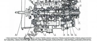
Switching circuit
1 236-1702060-A2 1st gear and reverse shift fork rod 2 236-1702014 Cover gasket 3 236-1702015-B2 Upper cover 4 236-1702129 1st gear and reverse fuse 5 236-1702127-A Spring fuse 6 236-1702132 Spring cup 7 236-1702087 Fork rod lock pin 8 316172-P29 Plug 9 200-1702083 Ball 10 236-1702122 Lever support gasket 11 216258-P29 Pin 12 2 52136-P2 Spring washer 10 12 252136-P2 Washer 10 spring 13 250513-P29 Nut 14 236-1702126 Driver axle 15 236-1702125 Driver for shifting 1st gear and reverse gear 16 252137-P2 Spring washer 17 250615-P29 Nut 18 236-1702170-A Breather 1 9 262522-P2 Plug 20 236 -1702025 Set screw 20 236-1702025 Set screw 21 236-1702225-B Gear shift lever 22 260311-P15 Plug 23 260310-P15 Plug 23 260310-P15 Plug 23 260310-P15 Plug ka 24 236-1702213 Bushing 25 236-1702129 Switching fuse 1st gear and reverse 26 236-1702106 Spring 26 236-1702106 Spring 26 236-1702106 Spring 27 236-1702215 Bolt 28 236-1702209-B3 Carter 29 236-1702206-B3 Remote shift mechanism housing gear assemblies 30 236- 1702235 Retainer spring cup 31 252161-P2 Washer 32 236-1702100 Retainer ball 33 236-1702229-A Fork rod head 34 312534-P2 Lock washer 35 310213-P29 Bolt 36 201499- P29 Bolt 10-6gх30 37 316121-P29 Plug K 1/4″ 38 236-1702216 O-ring 39 236-1702227 Gear shift rod fork 40 236-1702024 1st gear and reverse fork 41 236-1702221 Roller 42 314040-P2 Key 43 23 6-1702222 Gear shift lever 44 236-1702241 Gasket 45 236-1702240 Housing cover for remote gear shift mechanism 46 252135-P2 Spring washer 47 201454-P29 Bolt M8x16 48 236-1702027 2nd and 3rd gear shift fork 49 236- 1702053 Fork rod head 1st gear and reverse gear shift 50 236-1702028 2nd and 3rd gear shift fork rod head 51 236-1702033 4th and 5th gear shift fork 52 236-1702064 2nd and 3rd shift fork rod 53 236-1702074 Shift fork rod for 4th and 5th gears Link to this page: https://www..php?typeauto=6&mark=14&model=46&group=82