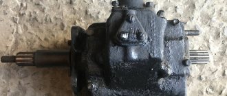
Gearbox (Gearbox) KAMAZ 141
During operation, there is a need to carry out inspection, control, lubrication, adjustment and repair work.
The most frequently performed gearbox maintenance work:
- Checking the serviceability of the divider control valve cable, eliminating detected faults;
- Check by external inspection that there is no oil leakage through the driven shaft seal and sealing gaskets;
- Adjusting the gap between the stop and the stroke limiter of the gear divider valve rod;
- Lubricating the support of the front and intermediate rods of the remote drive for controlling the gearbox;
- Cleaning the breather from dirt;
- Checking the oil level in the gearbox housing.
- Installation of the remote control gear lever;
- Installing the gearbox driven shaft flange;
- Changing the oil in the gearbox housing;
- Lubricating the divider control valve cable.
Features of some of the work are given below.
Back to Contents
Repair of remote transmission control drive to reduce effort when shifting gears
When repairing the remote transmission control drive, to reduce the effort when shifting gears, replace the lubricant in the three drive supports and the spherical heads of the lever joints. Pump fresh lubricant into the supports through grease nipples, screwing them in instead of the plugs in the support housings.
If, after lubricating the supports, the force on the lever when shifting gears has not changed or has not decreased sufficiently, disassemble the supports in the following order:
- Unscrew the bolts securing the adjusting flange;
- Remove the bolts securing the support on the clutch housing;
- Remove the rubber cover of the hinge joint, paying attention to the safety of the limit ball and spring;
- Unscrew the adjusting flange from the intermediate rod and pull the intermediate rod out of the support
- Disconnect head 6 of the front linkage, paying attention to the safety of the ball and spring;
- Disconnect the covers from the support located in the flywheel housing; remove the front link located in the camber of the cylinder block; Remove the shift lever support located on the front end of the block as described below. Remove the crackers, bushings, and spring from the support housings. Wash the parts and cavities of the supports with kerosene or diesel fuel, replace worn o-rings. When assembling, lubricate the rubbing surfaces with lubricant; Apply fresh lubricant to the bearing cavities. After assembly, adjust the remote drive.
Back to Contents
Adjusting the remote control drive of the gear shift mechanism
- Set the gearshift lever to neutral position;
- Loosen the tightening bolts of the tightening adjusting flange, unscrew the four connecting bolts and screw the adjusting flange onto the intermediate rod one or two turns;
- Unscrew the locknuts of the set screws. Lock the tip lever and the rod lever by screwing the set screws into the holes of the levers;
- Unscrewing the adjusting flange until its end comes into contact with the end of the rod flange along the entire plane, connect them with four bolts. Secure the flange to the intermediate rod by tightening the bolts;
- Loosen the set screw located on the front shift lever support by 31 mm, and the set screw located on the rear shift lever support by 16 mm. After this, secure them with locknuts.
Back to Contents
Adjusting the gap between the end of the cover and the stroke limiter of the divider activation valve rod
- Check the clutch release drive adjustment and adjust if necessary;
- Loosen and unscrew the valve stem stop nuts located on the pneumatic booster piston pusher. Connect the pressure gauge to the control terminal of circuit IV of the auxiliary brake drive of the pneumatic brake drive. Bring the pressure in the specified circuit to 7...7.5 kgf/cm;
- Smoothly press the clutch pedal all the way;
- Bring the valve stem stop of the divider switch until it comes into contact with the valve stem stopper and additionally move it towards the valve stem, ensuring a gap between the end of the valve cover and the stem stopper of 0.2...0.3 mm. Secure the valve stem stop in the indicated position with nuts and secure them with bend washers. When the pressure in the IV circuit of the auxiliary brake system drive drops to 6.2 kgf/cm, the gap may be increased to 0.6 mm; install a rubber dust guard on the valve stem and cover.
Back to Contents
Checking the oil level in the crankcase
To check the oil level in the gearbox housing, unscrew the plug from the oil filler neck, wipe the indicator dry and insert it into the filler hole until the plug stops in the thread, without screwing it in.
Back to Contents
Changing the gearbox oil
To change the oil in the gearbox, drain the oil while hot through three drain holes by unscrewing the plugs located in the lower part of the gearbox housings and in the lower part of the gear divider housing. Clean the magnets of the drain plugs from dirt and metal particles. Wash the gearbox housings and divider with engine oil. To do this, pour oil into the gearbox (12 l), crank the engine with the gearshift lever in neutral for 10 minutes, drain the engine oil from the gearbox and the divider, screw in the drain plugs and fill in the main lubricant TSp-15K to the upper mark of the level indicator .
Crank the gearbox with the engine in the neutral position of the gear shift lever for 3...5 minutes. Check the oil level and add if necessary.
Back to Contents
Checking the divider pressure reducing valve
To check the divider pressure reducing valve, remove it from the gearbox and install it on a stand, which must be equipped with a pneumatic system with an air pressure of 6...7 kgf/cm2 supplied to the valve inlet. A pressure gauge must be installed at the outlet of the valve to control pressure, ensuring a measurement accuracy of at least 0.05 kgf/cm.
Check the pressure of the outlet air, which should be 3.95...4.45 kgf/cm2. If the pressure does not correspond to the specified value, remove the seal, unscrew the plug and, selecting the required number of washers, adjust the valve and seal it.
Back to Contents
Removing and disassembling the divider control valve
To remove and disassemble the divider control valve during repairs, unscrew the bolts securing the three air ducts, disconnect the divider control valve from the support, unscrew the screws securing the cable clamp to the gear shift lever, remove the rubber bushing from the hatch seal support housing, unscrew the screws securing the control valve switch cover, carefully remove the cover with clips and spring, paying attention to the safety of the balls, and disconnect the cable from the switch lever.
During partial disassembly, unscrew the bolts securing the cover with the cable to the valve body, wash the valve parts and lubricate the working surfaces of the parts with grease 158. Assemble the control valve. Pull the cable all the way and measure the part protruding from the braid. In this case, the cable must be in a straight position. The size of the protruding part of the cable (before bending) is 24.5...26.5 mm. Lubricate the cable by pouring 10...15 g of TSp-15k oil into the cable braid using an oil can. If the cable breaks or the size of the protruding part of the cable does not correspond to the nominal size (24.5...26.5 mm), completely disassemble the crane and replace the cable. To do this, disconnect the valve cable with cover 3 assembly, as indicated above, straighten the bent end of cable 1, unscrew the union nut 6 and pull the cable with spool assembly out of the braid. Next, unscrew lock nut 1 (Fig. 50), unscrew cable end 3 from spool 6. Insert a new cable into the spool. Screw in the cable tip, ensuring axial movement of the cable; it should rotate freely by hand. Assemble the control valve.
Back to Contents
Checking the pneumatic system for leaks
When checking the pneumatic system for leaks: determine the location of the air leak by ear. Alternately moving the control switch to the HIGH GEAR position and screwing in the rear set screw (until it touches the lever, turn it another 1/4 turn and lock it with a lock nut. In this position, the drive shaft (with the gearbox removed) should turn by hand easily, without jamming; move the spool of the divider control valve to the HIGH GEAR position and adjust the engagement with the front set screw;
Through the inspection hatch in the housing of the divider gear shift mechanism, check the operating stroke of the lever until it stops at the set screws (16.5 ... 19 mm in the center of the hole in the lever); Lock and seal the set screws.
Back to Contents
Adjusting the remote control drive of the gear shift mechanism
- Adjustment of the gear shift mechanism control drive is carried out during the assembly process; fix the rod, screw in the screw;
- Secure the rod with a technological rod; set the lever at an angle D to the vertical;
- Screw the joint into the ball joint and align the axis of the conical pin with the axis of the hole. in the lever;
- By rotating the jet rod part, set the lever and rod in a vertical plane;
- Tighten the nuts;
- Unscrew the screw to the specified length and secure it with a nut;
- Remove the rod.
Back to Contents
Removing and disassembling the gear shift lever support
To remove and disassemble the gearshift lever support, tilt the cab, remove the noise-insulating cover of the gearshift lever, support seal parts, disconnect the air ducts of the divider pneumatic system, the generator mounting bracket, rods and fuel pump control cables, remove the front linkage head, unscrew the bolts securing the support bracket to the engine and remove the support, disconnect the divider control valve and the gear shift lever.
Disassemble the support, wash the parts, lubricate the rubbing surfaces with lubricant 158. Fill the support cavity with lubricant 158. After assembly, the tip of the lever must be rotated in mutually perpendicular directions with a force of 24.5...34.3 N (2.5...3.5 kgf) applied to conical surface of the lever tip.
Back to Contents
Adjusting the gaps between the divider synchronizer carriage and the gear divider shift fork nuts
To adjust the gaps between the divider synchronizer carriage and the gear divider shift fork nuts, remove the cover of the inspection hatch of the divider housing. Unlock and unscrew the two bolts securing the gear shift mechanism fork in the divider so that the shaft with the lever mounted on it moves freely in the axial direction, remove the divider shift mechanism.
Center the divider drive shaft using a special device, which consists of a housing with centering devices and two clamping levers. To do this, insert the centering cone into the inner cone of the divider drive shaft, securing the device to the divider housing by turning the clamping levers. At the same time, the alignment pins 3 center the device relative to surface B, ensuring a displacement of the shaft axis of no more than 0.2 mm.
Move the fork to the right until the block stops in the synchronizer carriage. Moving the roller with the lever attached to it to the right, ensure a gap of 0.3...0.6 mm, for which place an installation plate 0.3...0.5 mm thick between the mating plane of the divider housing under the gear shift mechanism housing and the lever head. Move the roller until the lever head rests on the plate. Screw in and secure the fork mounting bolts with bend washers. Reinstall the gear divider shift mechanism and inspection cover.
Back to Contents
Dismantling the gearbox mod. 152, 154
- Disconnect the divider from the gearbox;
- Disassemble the gearbox in the following order: Unscrew the bolts securing the upper cover of the gearbox and, screwing two bolts into the special threaded holes in the cover (after having unscrewed the plugs from them), remove it;
- Unscrew the nut securing the propeller shaft flange and remove the flange, remove the front and rear bearing covers of the drive, driven and intermediate shafts, screwing the fastening bolts into the special holes in the covers (when removing the covers, pay attention to the safety of the gaskets);
- Unfasten and unscrew the two bolts securing the thrust washer of the rear bearing of the intermediate shaft;
- Use pullers to remove the rear bearing of the driven shaft; to do this, use a special grip;
- Place the grip on the bearing groove and tighten with nuts;
- Screwing the screw into the yoke and resting the tip against the end of the shaft, remove the bearing.
Back to Contents
Disassembling the gear divider
- Remove the inspection hatch cover, the bearing covers of the drive and intermediate shafts of the divider;
- Remove the drive shaft of the divider, having first turned it flat on the synchronizer cone ring down towards the intermediate shaft drive gear, remove the synchronizer, unfasten and unscrew the bolts securing the bearing thrust washer;
- Press the intermediate shaft of the divider out of the bearing, remove the bearing from the housing;
- Remove the intermediate shaft of the divider;
- Unfasten and unscrew the two bolts securing the gear shift fork;
- Remove the shaft with the lever and remove the fork from the divider housing.
Back to Contents
Dismantling the gearbox mod. 161
- Disconnect the range multiplier from the gearbox;
- Disassemble the gearbox in the following order: Unscrew the bolts securing the upper cover of the gearbox and, screwing two bolts into the special threaded holes in the cover (after having unscrewed the plugs from them), remove it;
- Remove the front bearing covers of the drive and intermediate shafts (when removing the covers, pay attention to the safety of the gaskets).
Back to Contents
Dismantling the gearbox mod. 142
- Disconnect the clutch housing from the gearbox;
- Disassemble the gearbox in the following order: Unscrew the bolts securing the upper cover of the gearbox and, screwing two bolts into the special threaded holes in the cover (after unscrewing the plugs from them), remove it;
- Unscrew the nut securing the propeller shaft flange and remove the flange, remove the front and rear bearing covers of the drive, driven and intermediate shafts, screwing the fastening bolts into the special holes in the covers (when removing the covers, pay attention to the safety of the gaskets);
- Remove the bearing retaining rings; Unfasten and unscrew the two bolts securing the thrust washer of the rear bearing of the intermediate shaft;
- Use I801.30.000 pullers to remove the rear bearing of the driven shaft; to do this, use the I801.30.100 gripper;
- Place the grip on the bearing groove and tighten with nuts;
- Screwing the screw into the yoke and resting the tip against the end of the shaft, remove the bearing.
- Remove the rear bearing shell along with the intermediate shaft bearing. To remove the intermediate shaft bearing, resting against the wall of the gearbox housing, screw two bolts into the threaded hole of the bearing cup until it stops. Resting the tip against the end of the shaft, screw the screw into the plate until the bearing and cup are completely removed.
- When removing the rear bearing cup of the intermediate shaft from the gearbox housing, install a technological thrust washer between the rim of the 2nd gear gear of the intermediate shaft and the rim of the reverse gear block (to avoid breaking the teeth of the 2nd gear ring).
- Remove the first, driven and intermediate shafts of the gearbox.
- Use puller I801.32.000 to compress the axis of the reverse gear block. To do this, set the handle to the extreme right position, use a key to screw the screw into the axis of the gear block; then screw the handle onto the screw until the gear block axis is completely removed.
- Remove the gear block, bearings with spacer ring and thrust washers.
Back to Contents
Disassembling the driven shaft of the gearbox
- Remove the thrust ring and the front bearing of the driven shaft, to do this, use a grabber, install it on the bearing and tighten it with nuts.
- Screwing the screw into the yoke and resting the tip against the end of the shaft, remove the bearing, then the fourth and fifth gear synchronizer, and the fourth gear thrust ring. To do this, you need to: Remove the lock key from the groove of the washer and turn it until the splines of the washer and the shaft coincide; remove the fourth gear gear with the bulk bearing rollers;
- Compress the fourth gear bushing, remove the locking key with the spring; remove the gear and bearing of the third gear, the synchronizer of the second and third gears;
- The first gear gear and bearing, the first gear and reverse gear clutch, compress the first gear spline sleeve, remove the reverse gear gear and bearing, compress the reverse gear bushing;
- Remove the second gear and bearing.
Back to Contents
Disassembling the upper gearbox cover
- Unscrew the nuts and remove the gear shift lever supports, remove the cups, springs and retainer balls;
- Unscrew and unscrew the set screws securing the forks and rod heads, knock out three plugs, remove the gear shift rods, knock out the rod lock plugs, remove the balls from the cover and the locking device pin from the middle rod;
- Unscrew the spring cup and remove the spring, fuse and fuse bushing.
Assembly should be carried out in the reverse order of disassembly, taking into account the following features:
- When installing gears into a gearbox without replacing them, do not disassemble gears that have been run in together;
- When installing gears from spare parts, it is necessary to match the mating gears according to the contact patch and noise level on gear rolling machines. It is desirable to locate the contact patch in the pitch circle area;
- When checking pairs of gears on gear-rolling machines with and without braking of the driven gear, the noise should be smooth, low-pitched, without knocking or grinding. High-pitched noise is not allowed;
- To install the rear intermediate shaft bearing with a sleeve on the shaft installed in the gearbox and pressed by the front cover, use puller I801.31.000. To do this, install a washer on the tip, pass the bolts through the holes in the glass, and screw them into the threaded holes on the gearbox housing until they stop. Using the washer against the bearing, screw the screw into the plate until the cup with the bearing is completely installed;
- When assembling the driven shaft, pay attention to the correct installation of the bearing bushings. The holes on the bushings must be aligned with the radial holes on the corresponding journals of the driven shaft;
- When assembling the bulk bearing of the fourth gear gear, 88 rollers must be laid in two rows with an intermediate sleeve installed between the rows; when installing the front bearing of the drive shaft, the attachment ring must be installed inward to the end of the shaft;
- When pressing on the drive gear of the intermediate shaft of the gearbox and the gear of the intermediate shaft of the divider, they must be heated to a temperature of 90 °C;
- Pay attention to the serviceability of the gearbox synchronizers and the divider. The static force for removing the carriages from the neutral position should be 275...373 N (28...38 kgf) for both synchronizers of the main box, and 589...687 N (60...70 kgf) for the divider synchronizer. The blocking chamfers of the crankcase and pins should not show signs of significant wear.
- After assembling the driven shaft of the gearbox, the end clearances at the hubs of the gears of the first, second, third gears and reverse gear should be within 0.27...0.4 mm; along the hub of the fourth gear gear - 0.265...0.515 mm. The end clearance at the hub of the drive gear of the gearbox divider drive shaft should be within 0.375...0.715 mm.
- Before connecting the divider to the gearbox, adjust the gap between the divider gear shift fork holder and the synchronizer carriage;
- When installing the bearing caps of the drive shafts of the gearbox and divider, as well as the driven shaft cover, ensure minimal play of the shafts by selecting adjusting shims, for this: Measure with an accuracy of 0.05 mm the absolute size from the end of the outer ring of the bearing to the plane of the crankcase with the bearing pressed in all the way;
- For the covers of the drive shafts of the divider, for the cover of the driven shaft of the gearbox, place a sealing gasket on the mating surface of the cover, measure the size with an accuracy of 0.05 mm, determine the required total thickness from the adjusting shims, which should be less than the difference (b-c) by 0, 2…0.4 mm;
- Having selected the required number of shims, install the cover.
The rod clamps of all gears must clearly fix the rods in the neutral position and in the engaged gear position. Reverse gear and first gear should only be engaged when the reverse safety switch installed in the top cover is released.
The simultaneous engagement of two gears and oil leakage from the gearbox are not allowed.
When turning the clutch release fork shaft by hand, the clutch release clutch should move freely (without jamming) along the entire length of the drive shaft guide cover.
Check the air tightness of the connections of the air ducts of the pneumatic divider control system installed on the Model 15 gearbox with compressed air at a pressure of 588 kPa (6 kgf/cm2) supplied to the pressure reducing valve. In this case, it is necessary to use a technological divider control valve. In both positions of the divider control valve and the divider activation valve pressed all the way (6 mm stroke), the pressure drop in the air cylinder is allowed to drop no more than 147 kPa (1.5 kgf/cm2) for 40 s.
Adjust the engagement of the gear couplings of the divider synchronizer. All repaired and assembled gearboxes must be tested on a special stand.
The test bench must have the following equipment:
- A device that provides two modes of rotation speed of the input shaft: 1300 min-1 and 2600 min-1;
- A clutch connected to the drive shaft of the gearbox and disengaged when changing gears. The moment of inertia of the driven clutch parts should not exceed 12.7 Nm/sec2 (1.3 kgcm/sec2);
- A brake device connected to the driven shaft and providing a braking torque of 49.1 Nm (5 kgm) for first gear and reverse gear and 98.1...147 N.m (10...15 kgm) for other gears;
- A device that provides torque measurement on the driven shaft;
- Pneumatic system for switching the divider. The air pressure in the pneumatic system should be 588...686 kPa (6...7 kgf/cm);
- devices for measuring noise levels.
To lubricate the gearbox during testing, use engine oil heated to a temperature of 85 °C. Gearbox tests are carried out in two modes; no load and under load. When testing without load, check the operation of the divider and gear engagement. Test modes for gearboxes are given in Tables 9, 10, 11, 12.
Back to Contents
Table 9. Load test mode for model 142 gearboxes
| Drive shaft rotation speed, min-1 | Engaged gear in the main box | Included gear in the divider | Test time, min |
| 1300 | Neutral | Higher | 1,5 |
| 2600 | Higher | 1,5 | |
| 2600 | Consecutive switching of the divider “lower” - “higher” (two or three times | 1 | |
| 2600 | Sequential gear shift 3X-1-2-3-4-5-4-3-2-1-3X | Higher | 3 |
Back to Contents
Table 10 Test mode for transmissions of models 154 and 161 under load
| Drive shaft rotation speed, min-1 | Load on the driven shaft, N.m (kgf.m) | Engaged gear in the box | Included gear in the divider | Test time, min |
| 2600 | 49(5) | ZH | Higher | 1 |
| ZH | Lowest | |||
| 1 | Lowest | |||
| 1 | Higher | |||
| 2 | Higher | |||
| 2 | Lowest | |||
| 98, 1-147, 1(10…15) | 3 | Lowest | ||
| 3 | Higher | |||
| 4 | Higher | |||
| 4 | Lowest | |||
| 5 | Lowest | |||
| 5 | Higher |
Back to Contents
Table 11. Test mode for model 142 gearboxes without load
| Drive shaft rotation speed, min-1 | Gear engaged | Test time, min |
| 1300 | Neutral | 1,5 |
| 2600 | » | 1,5 |
| 2600 | Sequential gearing ZX-1-2-3-4-5-4-3-2-1-ZX | 3 |
Back to Contents
Table 12 Mode of testing gearboxes of models 142 under load
| Drive shaft rotation speed, min-1 | Load on the driven shaft, N.m (kgf.m) | Gear engaged | Test time, min |
| 2600 | >49(5) | ZH 1 | 1,5 |
| 98D…147D(10…15) | 2 3 4 5 |
After testing, drain the gearbox oil while the duo is still hot. Clean the magnets of the drain plugs from metal deposits.
Back to Contents
Installing the gearbox on the engine
- Check the condition of the drive shaft using a test spline mandrel with a height of at least 30 mm, which should move freely (without jamming) along the shaft splines, then lubricate the splined end with a thin layer of lubricant 158;
- Do not allow sharp impacts, and do not load the driven clutch discs with the weight of the gearbox or the force of the lifting mechanism to avoid breaking the clutch and the front bearing of the drive shaft located in the crankshaft;
- After installing the gearbox, check the full stroke of the clutch release clutch, equal to 35...43 mm. This stroke corresponds to a lever movement of 40...50 mm, measured at a radius of 90 mm;
- Before installing the remote mechanism, lubricate the working surfaces of the heads and rod supports with lubricant 158;
- Install the mechanism heads and tighten with coupling bolts.
Rocking of the heads on the rods is not allowed; the sealing covers of the heads of the remote mechanism rods must tightly cover the seating surfaces. When changing gears using a remote mechanism, sticking of the rods in the supports is not allowed. The gearshift mechanism latches should be clearly felt both in neutral and in any gear in the gearbox; Pour 12 liters of TSp-15K oil into the gearbox and carry out a three-time check to start the engine with the starter. In this case, the clutch must be disengaged; Check the correct installation of the clutch and gearbox with the engine running at a crankshaft speed of 1800...2000 rpm by checking:
- No jamming of clutch release mechanism parts.
- Clean clutch release. To do this, disengage the clutch completely, ensuring that the clutch release travel does not exceed 12 mm. This corresponds to a lever movement of 16mm measured over a 90mm radius. In this position, first gear and reverse gear should be engaged without grinding, and when direct gear is engaged, the driven shaft should not rotate. Repeat the check at least three times.
- Noisy operation of the gearbox (sharp uneven noise and knocking are not allowed).
- Gear shiftability in the main gearbox. Gear shifting should be done with the clutch disengaged without much effort and without jamming; engaging synchronized gears with a grinding noise is not allowed. In the gearbox, shift gears in the low and high gears of the divider.
- Shiftability of the divider gears. To do this, supply compressed air at a pressure of 490...588 kPa (5...6 kgf/cm2) to the pressure reducing valve and make two or three gear shifts of the divider, sequentially moving the control valve switch to the upper and lower positions and moving the divider activation valve rod by 6 mm , having previously disengaged the clutch.
- The gear shift of the divider should be clear, without delay.
- Shifting the divider gears without disengaging the clutch is not allowed. In both positions of the divider control valve switch, check the tightness of the connections and the valve.
- No oil leaks. Oil leakage is not allowed. The formation of oil stains without drop formation is allowed in the places of the stuffing box seals and installation of breathers.
Note
If a stand is not available, test the gearbox in an unloaded vehicle on level ground.
The order of gear shifting and the driving time in each gear according to the table for testing the gearbox under load at an engine speed of 1400...1800 min ~1.
When testing gearboxes, check:
- Ease of gear shifting. When shifting second, third, fourth and fifth gears, grinding noise is not allowed. Engage reverse gear and first gear only when the shafts are stopped;
- Torque on the driven shaft. At a rotation speed of the drive shaft of 2600 rpm, the torque on the driven shaft should not exceed 9.81 N.m (1 kgf.m); self-switching off gears (not allowed);
- The presence of sharp uneven knocks, indicating malfunctions of components and parts (not allowed).
Back to Contents
Removing the gearbox from the car and installing it
To remove the gearbox:
- Drain the oil from the gearbox housing. Tilt the cab, remove the platform floor panels to provide access to the gearbox; disconnect the batteries from the electrical circuit, disconnect the terminal connecting the main switch to the vehicle frame (the terminal is located on the battery box); disconnect and remove the wire connecting the starter relay to the “+” terminal of the battery; remove the hose connecting the engine intake pipe to the air cleaner connecting pipe by unscrewing the nuts and removing the bolts of the tie clamps; disconnect the plug connections of the tachometer, speedometer, trailer socket, brake light sensor, reversing lights, pressure drop indicator sensors in the receivers; disconnect the brackets securing the muffler to the divider housing; remove the pneumatic hydraulic booster clutch;
- Disconnect the yoke flange of the propeller shaft of the middle axle from the flange of the driven shaft of the gearbox by unscrewing the nuts of the fastening bolts, remove the spring washers and remove the bolts; loosen the tightening straps and remove the connecting hose of the ejector pipe; disconnect the air lines from the trailer brake control valve with a two-wire drive;
- Loosen the bolts securing the front supports of the power unit; unscrew the nuts of the bolts securing the rear engine mounts and remove the bolts; Unscrew the bolts securing the support beam to the frame; Unscrew the bolts securing the gearbox support to the transverse beam;
- Hang the power unit by the eye bolts of the gearbox; place wooden blocks under the front and rear halves of the second frame cross member and lower the power unit (the thickness of the blocks should be such that when the power unit is lowered, the rear support brackets are 50 mm higher than the rear support cushions); Unscrew the pinch bolt of the front linkage lever of the gearbox control drive; disconnect the front linkage from the lever, remove the rubber boot, remove the ball and spring from the ball head of the lever tip;
- Disconnect the three bolts securing the splitter control air ducts from the block on the engine side, unscrew the starter mounting bolts;
- Install the chain grips of the lifting device by the eye bolts on the gearbox, unscrew the bolts securing the clutch or splitter housing to the engine flywheel housing; move the gearbox back until the drive shaft exits the clutch housing, remove it and install it on the trolley.
Back to Contents
Gearbox Installation
- Before connecting the gearbox to the engine, place 15 g of lubricant 158 into the cavity of the front bearing of the drive shaft, located in the crankshaft bore; lift the gearbox and install it in place, having previously installed the clutch release clutch, a hose for supplying lubricant to the pressure bearing and release springs.
- Screw in the bolts securing the splitter housing to the engine flywheel housing. Screw in the starter mounting bolts; connect the divider control pipelines to the connecting block. Connect the front linkage to the lever, after inserting the ball and spring into the ball head of the lever; Screw in the pinch bolt of the front linkage lever of the gear mechanism control drive. Adjust the remote drive for controlling the gear shift mechanism.
- Hang the power unit by the gearbox eye bolts.
- Screw in the bolts securing the transmission support support to the cross beam, remove the wooden blocks from under the second frame cross member and lower the power unit onto the supports; screw in the bolts securing the support beam to the frame; insert the bolts into the holes in the rear supports of the power unit, tighten the self-locking nuts.
- Tighten the front power unit mounting bolts.
- Connect the air lines to the trailer brake control valve with a two-wire drive; put on the connecting hose of the ejector pipe and secure it with tightening straps.
- Align the holes in the yoke flange of the propeller shaft of the middle axle with the holes in the flange of the driven shaft of the gearbox; insert the bolts into the holes, put on the spring washers, and tighten the nuts. Install the pneumatic hydraulic clutch booster.
- Attach the muffler mounting bracket to the gearbox housing by screwing in the bolts.
- Connect the plug connectors of the tachometer, tachograph (speedometer), semi-trailer socket, brake light sensor, reversing light, pressure drop indicator sensors in the receivers.
- Place the hose connecting the engine intake pipe to the air cleaner connecting pipe; put on the clamps and secure the hose by inserting bolts into the holes of the clamps and tightening them with nuts; connect the wire connecting the starter relay to the “+” terminal of the battery; connect the ground switch terminal to the car frame (the terminal is located on the battery box); connect the batteries to the vehicle's electrical circuit. Install floor shields.
- Pour oil into the gearbox housing.
- Lower the cab.
- Check and, if necessary, adjust the free play of the clutch pedal.
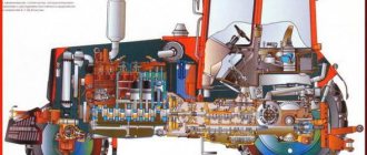
Design and principle of operation
Here, for example, is how the Kamaz gearbox (model 154) works:
The principle of operation, aimed at improving the performance of the car, increasing the speed of movement and allowing to save fuel, can be imagined as follows. When 1st gear is engaged, the clutch mechanism connects the gearbox shafts and the manual transmission. The initial rotational moment or KM (torque) is supplied from the Kamaz engine to the transmission. As soon as the speed increases, the synchronizer teeth are connected to the drive shaft of the internal combustion engine. Rotation is transmitted to the intermediate shaft of the box, the coefficient decreases, and the speed increases.
The traditional gearbox 152 or 14 is a five-speed, mechanical one, installed in order to simplify the design and increase the reliability of the product.
But there are other options:
The 14th model of the gearbox on the latest versions of the truck has been improved. The result is a new KamAZ 154 gearbox, which has several advantages over the classic old “five-speed”:
4th and 5th gears no longer slip out like they did with the old gearbox. Note that the 154 model or 15 is designed to operate on engines with a torque of 1100 Nm. These are modifications of the Kamaz 55111, 43118 and others.
Gearbox with divider
The 5-speed gearbox is normal, intended for single cars. 10-speed - improved Kamaz gearbox with divider. Essentially, these are the same gearboxes, but in the case of the 10-speed gearbox, a gearbox is added. Together with the gearbox, it creates 10 forward speeds and 2 reverse.
Control technology in difficult conditions
Traffic safety depends on many factors. This includes the technical condition of the car, the quality of the fuel, and the qualifications of the driver. Special attention is paid to external conditions, as they can change dramatically.
Climb
Driving up a hill should be accompanied by turning on the reduced H mode. This makes it easier to overcome slopes and obstacles, because the transmission begins to work at full capacity.
Descent
The slide down the hill must be carried out with the power unit always running. Under no circumstances should you turn it off - this is not a passenger car! This can stop the power steering, which will block the truck's steering. One can only guess what this threatens.
If difficulties arise with the brakes, Kamaz has the ability to connect an auxiliary system. But in this case, you cannot use the clutch and change speeds.
Severe wheel slip
Wheel slip is possible on various road surfaces, but it often happens on ice. Therefore, in winter it is recommended to use chains that increase the coefficient of traction. If the Kamaz skids, experienced drivers recommend removing your foot from the clutch and engaging the differential. There is a special regulator on the shield that allows you to do this. The indicator on the panel will turn on.