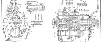
MAZ gearbox design diagram
MAZ gearboxes are installed on heavy-duty dump trucks, tractors and timber carriers.
The device is used for second and third gear. Today we’ll talk about the MAZ 238 gearbox diagram. This is an additional gearbox that increases the gear range and prevents engine overheating.
The design of the MAZ 238 gearbox is similar to a simple gearbox. The peculiarity of the MAZ gearbox connection diagram is that box 238 is mounted behind the main gear shift system. The parts of the units are connected to each other, then attached to the system crankcase.
Let us describe the MAZ checkpoint scheme in more detail.
The gearbox in MAZ is located between the crankshaft and cardan shaft. The MAZ gearbox diagram also includes: a crankcase, a mortar, and synchronizers. The speed of the equipment is regulated by changing gears - the movement of gears. The 238 gearbox is connected using 2 ball bearings, which are mounted on the input shaft. The clutch discs are located on the front splined end. The rear end of the permanent engagement fragment with the central gearbox is a gear ring. The secondary shaft is mounted on a cylindrical roller bearing on which the intermediate shaft is mounted. To secure the reverse intermediate gear, the MAZ 238 gearbox has an additional strong axle.
Thus, the design of a MAZ gearbox with a range multiplier is similar to the basic gearbox. The main purpose of using a range switch is to prevent motor overload. This is possible thanks to the increased gear range. The multiplier acts as an additional two-stage gearbox.
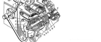
Divider device for MAZ
1 236-1005055 Ring nut 2 236-1701067-A Thrust ring B-40 3 200-1701192 Lock ring 4 236-1701243 Washer 5 238-1701285 Roller 6 238-1721027 Thrust ring 7 238- 1721033 Thrust washer for intermediate shaft 8 238- 1721048 Intermediate shaft for reduction gear 9 238-1721050 Driven gear of the intermediate shaft 10 238-1721056 Large driving disk 11 238-1721057 Small driving synchronizer disk 12 238-1721061 Thrust ring 13 238N-1721065 Stopper bolt ny 14 238-1721066 Large driven disk 15 238- 1721067 Small driven synchronizer disk 16 238-1721068 Thrust ring 17 238-1721069 Large thrust disk 18 238-1721070 Release spring 18 238-1721070 Release spring 19 238-1721071 Spring retainer 20 238-1721072 Small thrust disc 21 238-1721076 Glass 22 238 -1721078 Damper synchronizer disk 23 238-1721080 Spacer ring 24 238-1721105 Secondary shaft 25 238-1721118-B Gear 26 238-1721125-B Large pressure disk 27 238-1721126-B Press synchronizer disk no small 28 238-1721131 Roller spacer bushing 29 238-1721132 Thrust ring 30 238-1721136-B Small synchronizer disc holder 31 238-1721150 Carriage 32 238-1721240-B Flange 33 238N-1721242-A — 34 3611 Roller bearing 35 503 13 Single row radial ball bearing with locking groove 36 102313 Roller bearing rear 37 102212К1 Front roller bearing 38 70-592708М1 Front secondary shaft roller bearing 39 258072-П29 Cotter pin 40 310067-П2 Bolt 41 311701-П29 Nut 42 312503-П2 Washer Link to this page: https://www.kspecmash .ru/catalog .php?typeauto=6&mark=14&model=84&group=49
Source
Characteristics of the MAZ gearbox
All parts of the MAZ gearbox are protected by a reliable housing with a cast iron cover, which ensures the durability of the structure. The system can withstand heavy loads and is suitable for all climate zones. To prolong the operation of the speed box, timely maintenance is necessary. First of all, you should check the operation of the gears and control lever. The following problems indicate malfunctions in the MAZ gearbox design: jamming of gears, for example, 4th and 5th, difficult manual shifting, etc. If gears are switched with sound and grinding, the pressure in the pneumatic system may be increased.
To ensure safety on the road, it is necessary to monitor the serviceability of all mechanisms and systems of the vehicle.
Source of the article: https://www.snabavto.by/articles/skhema-ustroystva-kpp-maz/
Repair of YaMZ-238A MAZ gearbox
Page 1 of 3
Caring for the gearbox involves checking the oil level and changing it in the crankcase. The oil level in the crankcase must match the inspection hole. The oil must be drained while hot through all drain holes. After draining the oil, you need to remove the cover at the bottom of the crankcase, which houses the oil pump oil receiver with a magnet, rinse them thoroughly and reinstall them. In this case, you should pay attention not to block the oil line with the cap or its gasket.
To flush the gearbox, it is recommended to use 2.5 - 3 liters of industrial oil I-12A or I-20A in accordance with GOST 20799-75. With the gearbox control lever in neutral position, start the engine for 7 - 8 minutes, then stop it, drain the flushing oil and fill the gearbox with the oil provided in the lubrication card. It is unacceptable to flush the gearbox with kerosene or diesel fuel.
During operation of the gearbox drive, adjustments are possible:
— position of lever 3 (see Fig. 1) for gear shifting in the longitudinal direction;
— position of the gear shift lever in the transverse direction;
— blocking device for telescopic elements of longitudinal thrust.
To adjust the tilt angle of the lever 3 in the longitudinal direction, it is necessary to loosen the nuts of the bolts 6 and move the rod 4 in the axial direction to set the tilt angle of the lever to approximately 85 ° (see Fig. 1) in a neutral position in the gearbox.
Adjusting the position of the lever in the transverse direction is carried out by changing the length of the transverse rod 17, for which it is necessary to disconnect one of the ends 16 and, by unscrewing the nuts, adjust the length of the rod so that the gearbox control lever, being in a neutral position, is opposed to engaging 6 - 2 and 5 - 1 gears , had approximately an angle of 90˚ to the horizontal plane of the cabin (in the transverse plane of the car).
The gear shift drive locking device must be adjusted as follows:
— unpin pin 23 and disconnect rod 4 from fork 22;
— clean the earring 25 and the internal rod from old grease and dirt;
— push in the internal rod until the locking sleeve 15 “clicks”;
— loosen the nut of the earring 25 and, inserting a screwdriver into the slot of the shank of the internal rod, unscrew it until the angular play of the earring disappears;
— holding shank 24 from turning, tighten the locknut;
— check the quality of adjustment. When the locking sleeve 21 is shifted towards the spring 19, the internal rod should be pulled out to its entire length without jamming, and when the rod is pushed inwards until it stops in the grooves, the locking sleeve should move clearly with a “click” until the bushing stops at the lower protrusion of the earring.
When adjusting the drive, the following requirements must be observed:
— make adjustments with the cab raised and the engine not running;
- avoid bending and bending of the outer and inner movable rods;
— to avoid breakage, connect rod 4 to fork 22 so that the hole in the shackle for finger 23 is located above the longitudinal axis of rod 4;
— check the neutral position of the gearbox with the cab raised by freely moving lever 18 of the gear shift mechanism in the transverse direction (relative to the longitudinal axis of the vehicle). Roller 12, when the box is in the neutral position, has an axial movement of 30 - 35 mm, and the compression of the spring is felt.
The gearbox drive adjustments described above should be made when removing and installing the engine and cab.
Gearbox YaMZ 236: diagram, design and repair
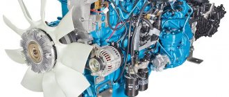
The transmission on the YaMZ 2361 is mechanical (5 steps), equipped with synchronizers in several gears. This device is produced by the Yaroslavl Motor Plant. They are equipped with heavy-duty MAZ vehicles. Depending on the configuration, YaMZ can be found on Ural vehicles and MARZ buses.
Appearance of the gearbox
The main technical characteristics of the transmission system should be considered.
Composition of the YaMZ gearbox
A unit such as the gearbox on the YaMZ 236 is equipped with a clutch housing made of reliable materials. The amount of fuel in the gearbox housing is about 5.5 liters. The transmission system includes a heavy-duty input shaft. The secondary shaft of the gearbox on the YaMZ 236 is supported by one part on the existing bearing (roller), and the other on the ball bearing. It should be noted that the roller bearings have intermediate shaft bearings.
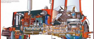
Longitudinal section of the gearbox
There is a special creeper. Thanks to it, it is possible to reduce the speed limit. The oil pump is efficient. The oil intake is covered with a mesh. This element has a magnet, which is necessary to attract metal microparticles that may be present in the oil. This system also includes a pressure reducing valve. Its main function is to maintain the outlet pressure at an optimal level during movement.
YaMZ gearbox diagram
In the top cover of the YaMZ 236 gearbox there is a mechanism that allows changing speed modes while moving. It is typical for special equipment that a gearbox (KOM) is installed, designed for a long service life. On a number of trim levels there is an electronic speedometer drive.
Transmission cover diagram
The weight of the gearbox together with the crankcase exceeds 240 kg. While the weight of the YaMZ 236 power unit reaches 1000 kg. Oil should be added to the YaMZ 236 gearbox through a special hole, which is securely closed with a plug.
Possible breakdowns
Gearbox malfunctions on YaMZ 236 can be as follows:
- the appearance of extraneous noise;
- reducing the amount of oil that is poured into the box;
- Difficulty switching gears;
- spontaneous switching off of speed modes;
- fluid leaks from the crankcase side.
In case of any of these manifestations, it is advisable to independently check the oil level in the box and how tightly all the fastening nuts and bolts are tightened. If this is not the problem, the vehicle should be sent to a service center for diagnostics. Here, technicians must use special equipment to check the integrity of the components of the gearbox (clutches, bearings, bushings, etc.) and evaluate the operating ability of the oil pump.
If necessary, mechanics at the auto center can adjust the locking clutch and the angle of the lever in the cab. In some cases, replacing faulty bearings and gears allows you to return the gearbox to an operational state. Without professional equipment, repairing a gearbox yourself will be complicated.
prokpp.ru
Disassembling the MAZ gearbox
Page 1 of 2
During repairs, the gearbox of the MAZ-5335 car and its modifications is disassembled in three stages: partial disassembly, general disassembly of components.
During partial disassembly, perform the following operations
— Remove the oil drain plugs, remove the oil pump intake cover mounting bolts 20 (Fig. 1) from the gearbox complete with the magnet, and remove the intake cover gasket from the intake.
— Unscrew the nuts of the remote gear shift mechanism to the upper roof, remove the spring washers, the mechanism and the gasket of the remote gear shift mechanism from the studs.
— Unscrew the bolts securing the top cover 13 to the gearbox housing 18, remove the top cover assembled with the rod and forks and the cover gasket from the crankcase.
Not available:
| № | Part code | Name | Part Information |
| 5551-1703301 | Lever | Quantity for MAZ-5337 2) MAZ-53371 3) MAZ-54323 4) MAZ-5516 5) MAZ-5551 6) MAZ-64229 1 Model 5551 Group Gearbox Subgroup Gearbox control mechanism Serial part number 301 | Not available |
| 018-022-25-2-2 | Ring | Quantity for MAZ-5337 2) MAZ-53371 3) MAZ-54323 4) MAZ-5516 5) MAZ-5551 6) MAZ-64229 1 | Not available |
| 5336-1703544 | Sealant | Quantity for MAZ-5337 2) MAZ-53371 3) MAZ-54323 4) MAZ-5516 5) MAZ-5551 6) MAZ-64229 1 Model 5336 Group Gearbox Subgroup Gearbox control mechanism Serial part number 544 | Not available |
| 5551-1703351 | Traction | Quantity for MAZ-5337 2) MAZ-53371 3) MAZ-54323 4) MAZ-5516 5) MAZ-5551 6) MAZ-64229 1 Model 5551 Group Gearbox Subgroup Gearbox control mechanism Serial part number 351 | Not available |
| 201456 | Bolt M8-6gх20 | Quantity for MAZ-5337 2) MAZ-53371 3) MAZ-54323 4) MAZ-5516 5) MAZ-5551 6) MAZ-64229 6 Uncoated coating | Not available |
| 252005 | Washer 8 | Quantity for MAZ-5337 2) MAZ-53371 3) MAZ-54323 4) MAZ-5516 5) MAZ-5551 6) MAZ-64229 8 Uncoated coating | Not available |
| 252155 | Washer 8L | Quantity for MAZ-5337 2) MAZ-53371 3) MAZ-54323 4) MAZ-5516 5) MAZ-5551 6) MAZ-64229 6 Uncoated coating | Not available |
| 250510 | Nut M8-6N | Quantity for MAZ-5337 2) MAZ-53371 3) MAZ-54323 4) MAZ-5516 5) MAZ-5551 6) MAZ-64229 6 Uncoated coating | Not available |
| 258055 | Cotter pin 4x36 | Quantity for MAZ-5337 2) MAZ-53371 3) MAZ-54323 4) MAZ-5516 5) MAZ-5551 6) MAZ-64229 1 Uncoated coating | Not available |
| 5551-1703448-10 | Shank assembly | Quantity for MAZ-5337 2) MAZ-53371 3) MAZ-54323 4) MAZ-5516 5) MAZ-5551 6) MAZ-64229 1 Model 5551 Group Gearbox Subgroup Gearbox control mechanism Serial part number 448 Additionally Not interchangeable with a part previously released under the same number | Not available |
| 5336-1703410-20 | Lever with washer | Quantity for MAZ-5337 2) MAZ-53371 3) MAZ-54323 4) MAZ-5516 5) MAZ-5551 6) MAZ-64229 1 Model 5336 Group Gearbox Subgroup Gearbox control mechanism Serial part number 410 Additionally Not interchangeable with a part previously released under the same number | Not available |
| 5551-1703351 | Traction | Quantity for MAZ-5337 2) MAZ-53371 3) MAZ-54323 4) MAZ-5516 5) MAZ-5551 6) MAZ-64229 1 Model 5551 Group Gearbox Subgroup Gearbox control mechanism Serial part number 351 | Not available |
| 5336-1703444 | Pad | Quantity for MAZ-5337 2) MAZ-53371 3) MAZ-54323 4) MAZ-5516 5) MAZ-5551 6) MAZ-64229 1 Model 5336 Group Gearbox Subgroup Gearbox control mechanism Serial part number 444 | Not available |
Gearbox YaMZ 238 - with a range multiplier, diagram, device - TD Spetsmash
To be completely precise, we will tell you something about those units that are equipped with a special device that allows you to expand the capabilities of the standard box without unnecessary interference in the design. We are talking about a YaMZ 238 gearbox with an increase demultiplier, or as it is otherwise called a divider. We will also use this very word, because on trucks they often use another additional box, which is also called a range multiplier, but it has a slightly different task, and we will talk about it in another article
At its core, the divider is the same gearbox, only it has only two speeds - standard (direct), in which torque is transmitted in the same way as in normal operation, and increased, in which the torque is average in value for two adjacent numbers. That is, for example, the torque of the third gear when the multiplier-divider is turned on will be equal to the arithmetic mean between the torques of the third and fourth direct gears.
Thus, the design diagram of the YaMZ 238 gearbox remains practically unchanged, and since the divider is installed in front of the main box, the number of output speeds remains the same. But by using a divider, the driver receives an additional advantage - it becomes possible to more accurately regulate engine power in accordance with the load and speed.
Consultation on technical issues, purchase of spare parts 8-916-161-01-97 Sergey Nikolaevich
Working principle of the part
If the switch is lowered, the spool moves to the position corresponding to direct transmission. In this case, the valve inlet is closed by a pusher.
There is no air supply in this position. The unloading hole is open. Cylindrical cavities communicate with the atmosphere.
When the switch is raised, the spool moves to the downshift position. Compressed air from one cavity enters another. A filter is connected to the atmosphere. Therefore, the operating principle of the MAZ box air distributor is determined by the position of the switch.
Where can I buy spare parts?
You can order the air distributor on our website. In the special MAZ catalog it is easy to find parts of excellent quality.
However, if you do not know how to choose components for a truck, we recommend that you contact a store consultant for help by phone.
We remind you that parts are delivered to all cities of Russia.
Switching mechanism for additional gearbox of MAZ-64227, MA3-54322 cars
(Fig. 49). Consists of pressure reducing valve 12, air distributor 6, air valve 5, inlet valve 8, working cylinder 1 and air ducts.
Reducing valve 3 (Fig. 50) serves to reduce the pressure of compressed air supplied from the vehicle's pneumatic system to 4.75 kgf/cm2 - the operating pressure of the gearbox pneumatic system. The air distributor 23 directs compressed air from the inlet valve 17 to one or another cavity of the working cylinder 25 and bleeds air from its cavities.
Rice. 49 Additional box switching mechanism: 1 - working cylinder; 2— reduction hose to the working cylinder; 3 - pneumatic valve; 4 — pipeline to the pneumatic valve; 5— direct transmission pipeline to the air distributor; 6—air distributor; 7—breather; 8— air distributor inlet valve; 9 — hose to the intake valve) 10 — reduction gear pipeline to the air distributor; 11 — pipeline for supplying compressed air to the pressure reducing valve; 12 - pressure reducing valve; 13 — direct transmission hose to the working cylinder
Rice. 50. Switching diagram of the additional box: 1 - condensation receiver; 2—protective valve; 3—reducing valve; 4 - consumer receiver; 5 - pneumatic valve; 6 — range switch; 7 — lever; 8— direct transmission pipeline to the air distributor; 9— control lamp; 10—additional box switching fork; 11—sensor; 12—top cover of the additional box; 13 — switching rods of the main box; 14 — top cover of the main coupling; 15 — reverse alarm sensor; 16 — pusher; 17 — inlet valve; 18 — breather; 19 — reduction gear pipeline to the air distributor; 20 — air distributor pistons; 21 — air distributor spool; 22 - reduction gear pipeline to the working cylinder; 23— air distributor; 24 — direct transmission pipeline to the working cylinder; 25 - working cylinder