04.03.2022 65 855 KAMAZ
Author: Ivan Baranov
Every motorist who has ever encountered driving a ZIL 130 or 131 car will say with confidence that there are practically no obstacles for this “iron horse”. However, if this is your first time driving such a unit, then you will probably be interested in the ZIL 130 gear shift scheme. Moreover, it is quite original and unusual for the average motorist.
[Hide]
Box ZIL-130 diagram
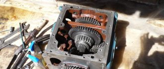
Moving the driven shaft gear forward engages first gear. 2nd gear is engaged by moving the synchronizer clutch back. If you move the synchronizer clutch forward, 3rd gear will engage. By moving synchronizer clutch 2 back, 4th gear is engaged. If you move the same synchronous clutch forward, 5th gear will engage. The intermediate shaft does not participate in the transmission of torque. Reverse gear is engaged by moving the 1st gear gear until it engages with the reverse gear unit.
A gearbox in which a change in torque is produced by changing the gear ratio. The most widespread are the stepped ones:
Gear shift diagram
gearboxes, where the gear ratio is changed by increasing or decreasing the gear ratio. Mechanisms that change the gear ratio continuously within certain limits are called continuously variable transmissions.
» The following types of continuously variable transmissions are used in cars: hydraulic (hydrodynamic and hydrostatic, otherwise called hydrostatic), mechanical (friction and pulse) and electric.
The most widely used continuously variable transmissions are hydrodynamic torque converters, which are usually installed in combination with stepped or planetary gearboxes. Such transmissions are called hydromechanical.
Step boxes are relatively simple in design and cheaper than continuously variable transmissions, but they have a limited number of gear ratios from three to five.
On off-road and heavy-duty vehicles, the number of gears increases due to the use of an additional gearbox. The higher the gear ratio of the gears in mesh, the greater the torque.
ZIL-130 gearbox diagram
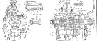
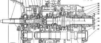
Step-by-step transmissions have forced manual control, while planetary and continuously variable transmissions are mostly semi-automatic and automatic. The five-speed gearbox is shown in Fig. 131. Primary (drive) shaft 1 is connected to the engine crankshaft through the clutch. The secondary (driven) shaft is, as it were, a continuation of the primary shaft and is located on the same axis with it.
One end of the secondary shaft is mounted on a roller bearing 10 mounted at the end of the primary shaft, so the secondary shaft can rotate independently of the primary; the second end of the shaft is installed in a ball bearing 8.
Gears are mounted on the intermediate shaft 9. All of them, except for the first gear gear, are made separately and secured to it with keys. To reduce noise during operation and increase durability, the gears that are in constant mesh are helical.
A design feature of the ZIL-130 car gearbox is the presence of constant mesh gears on the secondary shaft. These gears, thanks to special treatment (phosphating) of the mating surfaces of the shaft and the gears of their lubrication grooves, are installed on the shaft without special bushings and bearings.
Checkpoint diagram
In a MAZ-500 type gearbox, the needle bearings of the secondary shaft gears, which are in constant mesh, are lubricated with oil ... under pressure. To do this, a gear oil pump is installed against the front end of the intermediate shaft on the outside of the gearbox housing, driven into rotation from the front end of the intermediate shaft.
shaft The gears are engaged by moving the gear along the splines of the shaft. But in this case, the impact of the teeth is inevitable, since the peripheral speeds of the gears are different. For easy and shock-free gear shifting, it is necessary that the peripheral speeds of the gears being engaged are the same.
The peripheral speed of a gear depends on the number of revolutions of the shaft on which it is mounted and on its diameter: the larger the diameter of the gear and the number of revolutions of the shaft, the greater its peripheral speed. To equalize the peripheral speeds of the gears before engaging them, a special synchronizer mechanism is used, which ensures their silent and shock-free engagement.
Main features of the power unit and transmission of the ZIL-131
ZIL-131 is a domestic three-axle off-road truck. It was produced by the Likhachev plant from 1966 to 2002. The bulk of the vehicles produced were for army needs. The car contained many useful and progressive technical solutions for that time.
Operating order of ZIL-131 cylinders
The truck used a carburetor V-shaped eight-cylinder engine with ignition based on an electronic switch.
The engine camshaft and ignition system provide the following order of operation of the ZIL-131 cylinders: 1-5-4-2-6-3-7-8. Engine power output is at least 150 hp at 3200 rpm.
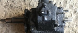
PTO power take-off.
Its name hints at the fact that it takes part of the engine torque and transfers it to special mechanisms. This could be a hydraulic pump or a utility equipment attachment. The PTO works in close conjunction with the gearbox, and is activated from the vehicle cabin. A huge amount of load and work falls on this small device.
Therefore, they always strive to make it strong and durable. There are 2 types of PTO, clutch dependent and clutch independent. The first one works when the engine is idling. Dependent PTO is lightweight, easy to install and requires almost no maintenance. They are mounted on a manual transmission and activated by the driver from the cab. An independent PTO can work with both manual and automatic transmissions.
It is installed on concrete mixers, road cleaning equipment, and agricultural machines. The place where the PTO is registered can be a gearbox, transfer case, engine, or the space between the engine and gearbox. KOM is a highly durable unit, but even it can break.
Often, breakdowns are immediately visible; the PTO either stops turning on normally or begins to make loud noise. Problems are solved in different ways, starting with simply tightening the nuts and ending with complete disassembly of the PTO. In any case, without the appropriate knowledge and skills, independent repair of the PTO is not recommended by the manufacturer.
WATCH THE VIDEO
Gear diagram
Primary shaft
The input shaft is made of steel 25 KhGM, the depth of the nitrocarburized layer is 0.6...0.8 mm, the hardness of the surface layer is HRCe 61...66, the hardness of the core is HRCe 37...46.
Basic data on shaft seats, permissible wear of splines, journals and shaft seats for bearings, as well as data on gears.
Thickness of straight spline teeth - 5, 805…5, 855
The diameter of the roller bearing seat is 43.980…44.007
The diameter of the shaft journal for the ball bearing is 60.003…60.023
Shaft end journal diameter - 24.975...24.995
Secondary shaft
The secondary shaft is made of steel 25 KhGM, nitrocarburization depth 0.8...1.1 mm, surface layer hardness HRCe 61...66, core hardness HRCe 37...46.
The runout of the secondary shaft journals relative to the axis is allowed no more than 0.05 mm. The use of necks on crumbled cemented layers of a fatigue nature is not permitted.
Parameters of the secondary shaft journal splines
The diameter of the journal of the front end of the shaft for the roller bearing is 29.939..29.960
The diameter of the journal for the ball bearing is 50.003…50.020
The diameter of the journal for the bushing of the constant mesh gear of the fourth gear is 47.003...47.020
The diameter of the journal for the second gear constant mesh helical gear is 60.920…60.940
Thickness of the tooth of the splined part of the shaft for the synchronizer:
second and third gears - 8.88...8.94
fourth and fifth gears - 10.90...10.95
The tooth thickness of the splined part of the shaft for the first gear gear is 10.88…10.94
Tooth thickness of the splined part of the shaft for the flange - 5.99...5.94
Intermediate shaft
The intermediate shaft is made of steel 25KhGM, nitrocarburization depth is 0.8...1.1 mm, surface layer hardness HRCe 58...61, core hardness HRCe 35...45.
The runout of the intermediate shaft journals relative to the axis is allowed no more than 0.04 mm. Faulty shaft journals can be repaired by chrome plating and then machined to their nominal dimensions.
Transmission repair needed
Signs of a ZIL 130 box failure:
the appearance of a characteristic hum while driving. In this case, you need to inspect the condition of the bearings and gears;
https://youtube.com/watch?v=VWyLgqqriM4
- Extraneous sounds are heard from the manual transmission. Typically due to wear on the retaining rings;
- Difficulty shifting gears is noted. This manifestation may indicate a reduced amount of transmission oil.
- transmission failure. In this case, you need to check the condition of the clutch and gear;
- Vibration began to be felt at a specific speed (it is advisable to check the fastening of the gearbox, cardan, and inspect the bearing).
Working fluid is poured into the inside of the crankcase
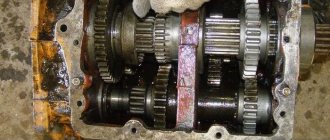
When disassembling the gearbox, it is important to prevent dirt from getting into it. Otherwise, the gears associated with the driven shaft may become jammed.
The oil level should be checked and topped up during maintenance 2. Kerosene should not be used to flush the gearbox; a special flushing fluid should be used. Only after this fresh oil is poured into the crankcase.
How does the gearbox of the ZIL 130 car work?
ZIL 130 and 131 cars are equipped with a three-way five-speed manual gearbox. The gearbox of this vehicle allows the driver to move forward at five speeds and backward at one. You can find a drawing of the device below. As can be seen in the diagram, the ZIL 130 and 131 gearbox is equipped with two inertial synchronizers, which include the second and third, as well as the fourth and fifth.
The drive shaft, together with the gear and ring gear to activate the fifth (direct) speed, is installed in the crankcase on bearings. In addition, a cylindrical roller bearing is mounted in the bore of the pulley itself, and the secondary pulley, in turn, rests on it. The intermediate shaft in the ZIL 130 and 131 box is mounted in the lower compartment of the crankcase. There is another gear installed on this shaft, which is in regular mesh with the input shaft (ID) disk. Here, the developers of models 130 and 131 decided to install wheels of second, third and fourth speeds.
Sectional diagram of the unit with all symbols
Identification of all transmission components
In addition, spur gears are mounted on the cardan, designed to activate reverse (reverse) gear and first gear. Also, activation of these modes is provided by a spur gear and synchronizer components mounted on the splines of the secondary pulley.
In addition, additional gears are mounted on the secondary shaft:
- to engage second gear;
- to activate the third mode;
- to turn on the fourth.
And these gear rings, when operating, are in constant engagement with the wheels mounted on the intermediate disk. The reverse movement unit is mounted on special roller bearings, which are located on an axis in the crankcase. Here they are installed quite securely. The reverse drive cardan also works in conjunction with the idler pulley through additional wheels.
As for the inside of the crankcase, the working fluid is poured here, so this part is always closed from debris and dust. The switching mechanism itself is installed here. It should be noted that the gearbox switching mechanism on ZIL 130 and 131 is designed in the same way as on GAZ 53.
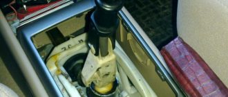
Switching circuit
The switching diagram for the ZIL 130 and 131 gearboxes is presented below. In general, the scheme is original, but if you believe the words of ZILovodov, then you can get used to it very quickly.
How the transmission lever shifts
Prevention of breakdowns with gearboxes
To avoid serious damage, vehicles should be diagnosed. When changing gearbox oil, you should use fuel that matches the vehicle system. When the gearbox is drained, you need to clean the magnet that is on the plug. Add new fluid to the inspection hole. The breather located on the crankcase hatch cover must be cleaned.
Thus, the ZIL 131 gearbox must be serviced periodically. This will be a guarantee that vehicles will not quickly lose their working properties.
How does the gearbox of a car of this brand work?
When the first speed is activated on the gearbox of a car model 130 and 131, the gear wheel begins to move along the grooves and engages with the cardan of the first gearbox mode on the intermediate shaft. In this case, the torque begins to transfer from the primary pulley through gears and other auxiliary elements to the secondary disk. The gear ratio is 7.44.
When the driver engages second speed, the clutch mounted on the synchronizer begins to act on the gear teeth of this transmission. As a result of the fact that this component is already functioning from the components of the intermediate gear, the torque begins to transfer from the primary element to the secondary element. In this case, the moment passes through all the wheels with teeth, as well as the synchronizer cardan. In this case, the gear ratio will be 4.1.
When the driver activates third speed, the synchronizer disc stops affecting the parts and elements of the second gear. The clutch will move along the splines and engage with the third-mode component of the gearbox of models 130 or 131. And this element, in turn, is already engaged with the third-speed wheel of the intermediate cardan. Thus, the torque begins to transfer from the primary pulley through auxiliary elements and the clutch to the secondary pulley. The gear ratio is 2.29.
Synchronizer operation
When a synchronized gear is engaged, the following occurs: the synchronizer carriage 2 together with the fork 9 or 10 moves towards the gear being engaged. In this case, the movement of the carriage through three clamps is transmitted to the cone rings 3, which are rigidly connected to each other using three locking pins 1, until they stop at the gear cone.
Due to the difference in the peripheral speeds of the engaged elements (gear and synchronizer carriage) and the axial pressure transmitted through the clamps that hold the carriage from free axial movement, a friction moment occurs on the conical surfaces. Under the influence of the friction moment, the carriage shifts relative to the block of conical rings until it stops at the locking surface of the pins 1, which prevents the free axial movement of the carriage. As a result, the peripheral speeds of the switched elements are equalized (synchronization occurs).
After equalizing the peripheral speeds of the switched elements, the locking surfaces of the fingers will not interfere with the axial movement of the carriage and the selected gear will be engaged without noise or shock.
For normal operation of ZIL-130 synchronizers and to prevent premature wear of the rings, it is necessary to correctly and timely adjust the free play of the clutch pedal. If the clutch “leads”, changing gears becomes difficult. If synchronized gears are turned on with noise, the cause of the malfunction must be immediately found out and eliminated.