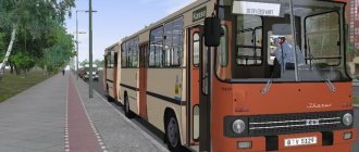
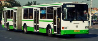
Since 1997, the Minsk Automobile Plant (Belarus) began producing a new model, the MAZ 105. This is a bus with a soft accordion-shaped joint in the middle part. Sufficient capacity is provided by the additional rear section. The length of the bus is 17.98 m, width – 2.5 m, height – 3.13 m. Due to the fact that the car has a large capacity, it is an almost ideal solution for cities with large passenger flows. The four doors of the model are quite wide, and the floor is low, which is very convenient; there is also a ladder and a special place with a mount for a wheelchair.
History of creation
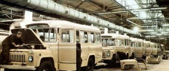
The year of birth of bus production at the Minsk Automobile Plant can be considered 1992, when a license agreement was signed with Neoplan (Germany, now the company belongs to the MAN concern). As a result, only five licensed buses were built in “pure form” (their price was prohibitive, about $200,000). And then the plant began to introduce domestic components, at the same time adapting the design to our conditions. For example, the plant was unable to organize the production of a portal drive axle and therefore had to make the bridge simpler, and at the same time raise the floor in the rear part of the cabin by 8 cm. Today, the share of imports - excluding the power unit - does not exceed 8 percent (these are glue, varnishes, paints, plastic, brake equipment, door opening mechanisms). The price of low-floor MAZ-103 buses in the basic configuration is about 40% of the original price.
Bus MAZ-105. Photo MAZ
The bus has been produced since 2000. The first prototype was built in 1997 , and over the next two years mass production of this model was prepared. A number of exhibition examples were built. Serial production began in 2000 . In 2002, the height of the engine compartment was reduced (previously it occupied space from floor to ceiling). In January 2009, a restyling was carried out, mainly affecting the front mask of the body. In 2014, production of MAZ-105 was discontinued; the last batch arrived in the summer of 2014 in Baranovichi. But the plant still had six body frames for this bus model, which were assembled at the end of autumn 2022. The buses produced after a three-year break arrived again in Baranovichi.
Detailed description, device
Body and interior. The body is all-metal, carriage type, load-bearing, articulated. The sides and roof are made of seamless galvanized steel sheet, the front part is made of fiberglass. The technology for producing the body under license was borrowed from the German ]Neoplan[/anchor] - the frame is welded from box profiles and then sheathed with steel sheet. Frame blanks - galvanized rectangular pipes - are fixed on a large sheet in special jigs. This is how the sides, floor and ceiling are welded. On the slipway they are combined into a single whole. The wheel arches and part of the floor are covered with stainless steel sheets. Paint – polyurethane multicomponent. They mix it in their own laboratory. The color is selected at the request of the customer from a huge number of colors and combinations.
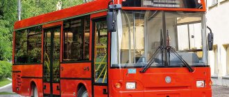
At the end of 2008, the MAZ-105 received new front and rear outer body panels. Blocks of vertically located round lights will appear at the rear, and at the front, the glazing area of the route indicator will increase, and instead of rectangular headlights, several “spot” headlights from Hella will be installed horizontally, similar to the restyling of the MAZ-103.
Articulated bus MAZ-105. Photo Wikipedia
The glass is glued in, which has a positive effect on the rigidity of the body. It has four sliding doors (two double-leaf doors for passengers, the rear half of the front door, the front half of the front door for the driver).
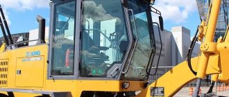
The driver's cabin is fenced off from the passenger compartment as standard. It is possible to equip with a partition with an entrance to the driver's cabin from the passenger compartment. The driver's cabin is quite spacious . The controls are located well and do not overlap each other. In front of the driver there is an instrument panel on which there is a speedometer (VDO), voltage indicator, pressure gauges, tachometers, coolant temperature and oil pressure indicators, as well as a buzzer. To the right of the instrument panel there are buttons for controlling lights, doors, announcing current/next stops, controlling the transmission (if automatic is installed), differential locking, stopping brake control, and an hazard warning button. On the left are control buttons for light, ventilation and other systems.
The bus is equipped with a movement lock when the doors are open, which is disabled by a button with the symbol (B) on the front panel in the driver’s cabin.
On models of the MAZ family, two types of route indicators - an electronic board and route indicators with replaceable route signs. The front route indicator is located on the front of the bus above the windshield, the side indicator is located above the side windows between the front and middle doors, the rear route indicator is located on the rear of the structure above the rear window.
The MAZ-105 is equipped with non-removable hard passenger seats. two types of hard seat fastenings used on buses . In the first case, the stand is screwed to the wheel arch or to the step of the engine compartment. In the second case, the stand mount is mounted with one side on the side wall, and the other side through the stand to the floor. Handrails are made of metal pipes coated with powder paint. The handrail pipes are connected with aluminum brackets.
Buses until 2001 had a floor-to-ceiling engine compartment opposite the second door, after which the engine compartment was significantly reduced.
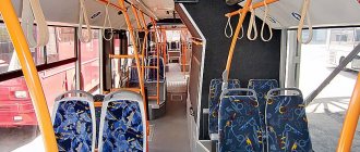
The seats are arranged in a three-row pattern, which makes the interior spacious for seated passengers. On the left side there are double seats . On the starboard side - single . Opposite the middle door there is a large storage area. The total passenger capacity is 160-175 people. The number of seats is 30-36.
The door drive is pneumatic, manufactured by Festo or Camozzi. The drive is equipped with an emergency opening valve inside the bus above the door and an emergency opening valve outside, on the side of the doors.
Power unit. MAZ-105 has a number of interesting features. Unlike many low-floor buses, the engine is not located in the rear overhang, but within the wheelbase of the “tractor”. The engine compartment is located on the left opposite the second door and occupies the entire space from floor to ceiling in the case of Renault engines; the space from the floor to the sill line in the case of a Mercedes engine . Buses produced in 1997-2004 were equipped with Renault MIDR engines and a Praga gearbox. Renault MIDR engines 250 hp turned out to be much more reliable than domestic engines (modification MAZ-105.041). In addition, drivers liked the high torque and impressive power. However, since 2002, the MAZ-105 has received Mercedes-Benz and Voith automatic transmissions . Since the end of 2004, only this modification has been produced.
Articulated city bus MAZ-105. Photo Wikipedia
The power unit is located on the left side at an angle of 7° to the longitudinal axis of the bus. It is attached to the frame at three points (one front and two side). In addition, there is transmission support When the engine is not running, the rear support should not bear the load. To fulfill this condition in operation, it is possible to adjust the rear support. This is done to prevent the occurrence of large stresses in the crankcase parts of the power unit. Buses with French engines had an engine compartment the entire height of the cabin: on the side there was a radiator for the cooling system and a large hydraulically driven fan. On buses with German engines, they are shifted lower and forward, which made it possible to make the engine compartment lower.
The bus is equipped with an engine brake flap , which serves to increase the service life of the main brake system, being a mechanism of the auxiliary brake system. When the engine is running, the damper is installed along the exhaust gas flow; when the engine brake is applied, it is perpendicular to the gas flow, creating a certain backpressure at the exhaust. At the same time, the fuel supply is turned off using a pneumatic cylinder connected to the engine stop bracket.
The split type fuel supply system for the engine consists of a fuel tank, low and high pressure fuel lines, a coarse filter, a fuel priming pump, a fine filter, a high pressure fuel pump and injectors. The fuel tank is installed on the right side along the bus in a niche and is attached to the frame with clamps. Polyamide low-pressure fuel lines are placed in protective shells and secured with clamps to the frame. At the customer's request, electric fuel heating can be installed in the engine fuel supply system.
The fuel supply control drive is electronic remote. The fuel pedal has an induction sensor , the signal from which is sent to the electronic engine control unit.
supply system consists of an intake connected to the air filter by a corner pipe and an air duct connecting the air filter and the engine intake manifold. To monitor the clogging of the air filter element, there is a clogging warning sensor. The engines have a turbine for pumping air. The air filter used in this system is dry type, two-stage, with a dust collection hopper and a replaceable cardboard filter element.
The cooling system is liquid, closed type, with forced circulation of coolant, designed for the use of low-freezing coolant. The engine cooling system is combined with a heating system for the passenger compartment and driver's workplace. The optimal coolant temperature in the system when the engine is running (80-98 °C) is maintained automatically by thermostats and fan performance that varies depending on the coolant temperature.
Interior of the MAZ-105 bus. Photo MAZ
The radiators of the engine cooling system and intercooling of the charge air are located in the upper part of the engine compartment directly above the engine and are installed along the left wall of the car. The fan is hydraulically driven, since a belt drive would be even more difficult. The pump is a high-pressure gear type. The pump converts the rotational movement of the input shaft into the energy of the flow of working fluid. At the rear on the left side there is an air intake for the cooling system, on the rear wall there is a place for the air outlet blown by the fans. Additionally, there is an opening hatch on top of the engine compartment. Thus, at the same time as the radiators are cooled, the engine compartment is also ventilated.
The oil radiator is tubular-plate, air-cooled, located in front of the water radiator. Liquid heaters Thermo 90S (Webasto) can be installed on buses. Liquid heaters are designed for pre-heating of the engine , which facilitates cold starting of the engine, as well as for long-term automatic maintenance of the thermal state of the idle engine, passenger compartment and driver's seat. The heater is supplied with fuel through separate fuel lines from the main fuel tank. The power supply system for fuel heaters can, at the customer's request, be equipped with an electric fuel heating system (supply voltage 24 V DC). heating system consists of an electric heater, a fuel intake, fuel lines and a fuel filter.
The Sachs clutch is a dry, friction, single-disc clutch with a diaphragm extension spring. The buses were equipped with a 5-speed Praga 5PS 114 gearbox. The manual transmission control drive is remote, mechanical. It consists of a gear shift lever mounted on the floor of the bus and a transmission mechanism, including a shaft line suspended on sliding spherical supports, reaction rods and a device for coordinating the movements of the gear shift lever and the movements of the gear shift mechanism shaft. To engage a gear, two movements must be made - the selection movement and the gear engagement movement.
Since 2004, buses have been produced only with a hydromechanical transmission from the German company Voith . It has three gears, the first using a torque converter. Gears are switched automatically; shifting can be forced to be limited according to the principle of “no higher than second” or “only first”. Modes are switched using buttons on the front panel.
Restyled bus MAZ-105. Photo Wikipedia
Bridges and suspension. MAZ-105 – articulated, three-axle. Its front part (“tractor”) has a front axle, a rear drive axle, and the “trailer” is equipped with one non-drive axle.
The rear drive axle is made according to the classical design with a double spaced main gear and a bevel gear offset from the transverse axis of the bridge. It consists of a crankcase, a central bevel gear, a differential lock, planetary wheel gears and shoe brakes. To ensure a low floor in the cabin, the rear axle gear housing is shifted as far as possible towards the left wheel.
Until 2004, MAZ-105s were equipped with a differential lock (a rather unusual thing for the global bus industry), which allows you to easily start from a stop on densely packed snow or ice. It is activated and deactivated by a button on the front panel. The blocking is controlled using an electric pneumatic valve.
The rear suspension of the “tractor” is dependent, pneumatic on 4 air springs with four shock absorbers and one body position adjuster. The rear axle is hinged to the body by a reaction rod system consisting of two lower reaction rods and one upper V-shaped reaction rod. Reaction rods perceive forces from reaction and braking moments and transmit traction force. The upper reaction rod is V-shaped and consists of a head, on the cylindrical surfaces of which the ends of the pipes are mounted and welded, and the heads are screwed onto the other ends of the pipes. To dampen vibrations that occur when the bus moves over uneven roads, the suspension is equipped with four collapsible double-acting telescopic hydraulic shock absorbers. The rear axle of the “trailer” is similar in design to the rear axle of the “tractor”.
The front axle consists of two suspension arms and wheel-hub assemblies attached to them through a kingpin. The second ends of the suspension arms are attached through a pin and rubber bushings to the bus frame. The steering knuckle is mounted on a kingpin on bronze bushings, closed on the side of the suspension arms with O-rings.
The front suspension is dependent, pneumatic on 2 air springs with two shock absorbers and one body position adjuster. Installation of the front axle perpendicular to the longitudinal axis of the bus and adjustment of the longitudinal angle of inclination of the kingpin is ensured by changing the lengths of the reaction rods. The front axle suspension consists of supports, a reaction rod system, two shock absorbers, two air springs and a body position regulator.
The front axle is pivotally connected to the body by a reaction rod system consisting of two upper reaction rods, two lower reaction rods and a transverse reaction rod. The upper and lower reaction rods perceive forces from the reaction and braking torques. The transverse reaction rod absorbs lateral loads. The transverse reaction rod (Panhard rod) ensures the stability of the bus when driving on roads with a side slope and when turning.
Model MAZ-105 before restyling. Photo Wikipedia
double-acting telescopic hydraulic shock absorbers are installed in the suspension The shock absorbers are mounted at one end on the front axle support brackets, and at the other end - on the bus frame brackets.
The vertical load from the weight of the bus is transmitted through four air cylinders. To maintain the floor level in a horizontal position at a certain height, two body position regulators , which are connected to the rear axle by levers and adjusting rods.
Pneumatic system receivers are reliably protected from the worst enemy - corrosion. They are located under the roof on the left side. All pipelines are made of polyamide: cheaper than copper and more durable than steel. The connections of the pneumatic lines are very reliable, so that the compressed air does not escape unnecessarily into the atmosphere. The control leads are arranged in one place – the pneumatic equipment diagnostics unit.
Wheels and tires. Wheels - disc, adapted for tubeless tires, rim flange inclination 15°. Centering the wheel on the hub is done along the central hole of the wheel disk. The front wheels are single, the rear wheels are double.
For ease of tire inflation, the rear inner wheels are equipped with a valve extension, which is secured with a union nut on the wheel valve stem. The wheels are secured to the hubs with nuts and conical pressure washers. The buses are equipped with model 11/70 R 22.5 D-7M tires.
The steering control of MAZ vehicles is developed on the basis of components and assemblies of serial MAZ vehicles. The steering mechanism with a built-in distributor consists of a screw and a ball rack nut that meshes with a gear sector. Semicircular threaded grooves on the screw and rack nut form a spiral channel, which is filled with balls when assembling the steering mechanism. The gear sector is mounted on double needle bearings in eccentric bushings with a number of holes at the ends of the outer surfaces of the bushings, offset relative to the axis of the bearing holes, which makes it possible to adjust the sector-rack gearing by turning the bushings.
YaMZ engines are equipped with NSh-32 hydraulic booster pumps with a belt drive from the crankshaft, completely similar to those used on MAZ vehicles.
Bus MAZ-105 on the road. Photo Wikipedia
Articulation node. The design of a reliable articulation unit was largely determined by the location of the engine in the front part of the bus and the planned operating conditions. The joint between the first and second sections consists of a coupling unit, a frame position stabilizer, a frame rotation mechanism, a flexible joint and a turntable with a guard.
The coupling unit transmits the pulling force from the first section to the second, ensures the angular movement of the sections relative to each other in the horizontal and vertical planes, and also guarantees the mutual twisting of the sections relative to the longitudinal axis of the bus and the movement of the articulation frame. The frame position stabilizer serves to orient the rotating frame in space so that the folding and skew (torsion) angles between the first and second sections are divided in half by the frame. The joint assembly is lined with a flexible joint with an “accordion” made of foreign-made polyester materials.
On buses manufactured before 2001, frame rotation mechanisms using ShS-30 spherical bearings are installed. Since the beginning of 2001, frame rotation mechanisms have been used using ball pins similar in design to steering rods with ball pins.
The turntable of the cabin is designed for the safe movement of passengers between the cabins of the first and second sections. The turntable consists of two semicircular turntables connected by hinges to supports. The rotating plates are supported by 8 support rollers. The vertical movement of the plates is limited by four rollers mounted on eccentrics. For the safety of passengers on the turntable, a metal fence is attached to the frame.
Brake system. The buses are equipped with working, parking, spare, auxiliary brake systems and a stopping brake, as well as outputs for monitoring and diagnosing the pneumatic system and supplying other consumers with compressed air. The service brake system acts on the brake mechanisms of all wheels. The service brake system is equipped with an anti-lock braking system (ABS). The rear circuit can be equipped, upon customer request, with an additional anti-slip system (ASR). The parking and spare brake systems act on the brake mechanisms of the rear axle, which are driven by brake chambers with spring energy accumulators. The drive of spring energy accumulators is pneumatic, double-circuit.
Articulated low-floor city buses MAZ-105. Photo Wikipedia
The parking brake system serves as a spare one. It is designed to brake the bus in the event of a complete or partial failure of the service brake system. When the parking brake system is activated, the control valve handle is set to its extreme fixed position . The compressed air that compresses the power springs of the energy accumulators is released into the atmosphere, and the springs activate the brake mechanisms. When the emergency brake system is engaged, the parking brake control valve handle is held in any intermediate non-fixed position . As the angle of rotation of the handle increases, the braking intensity increases due to a decrease in air pressure compressing the springs of the energy accumulators.
The stopping brake acts on the brake mechanisms of the rear axle. When you turn on the stopping brake with a button located on the instrument panel, or automatically when opening any of the bus doors, pressurized air is supplied to the brake chambers of the rear axle.
Auxiliary braking system - a remote-controlled engine brake, a flap in the exhaust system and a pneumatic drive to shut off the fuel supply. When the power unit is equipped with a hydromechanical gearbox, the functions of the auxiliary brake are performed by a hydraulic retarder. The auxiliary braking system is designed to slow down the bus on long descents.
brakes with two internal pads and an easily removable drum. The brake linings are asbestos-free, crescent-shaped, and are attached to the block with steel hollow rivets. The brake drum is bolted to the wheel hub.
Electrical equipment. The buses have a 24-volt electrical system, which is made according to a single-wire connection diagram. The minus is the bus frame connected to the minus of the batteries. A distinctive feature of the system is that the connection of wiring harnesses and the connection of a significant part of its products is carried out using plug connections.
Bus MAZ-105 on the streets of Minsk. Photo Wikipedia
On buses, 6ST-190A batteries The generator is self-excited from permanent magnets, the rated voltage of the generators is 28 V, and the rectified current is 108 A. Various types of generators depending on the engine. The RENAULT MIDR 06.02.26 engine is equipped with two VALEO A14N196M generators with a rated voltage of 28 V and a rectified current of 60 A each. Bosch generators are installed on buses with German Mercedes-Benz engines.
Starters are installed on buses Bosch, JF 24 (RENAULT MIDR 06.02.26 Y 41), D13HP605 (MIDR 06.20.45 R 41).
The exterior lighting system includes headlights, rectangular halogen HI fog lights, front marker lights, front turn signals, side turn signal lights, side marker lights, tail lights and license plate lights. The headlights are turned on using a key switch on the instrument panel. The fog lights turn on only after the side lights are turned on.
Interior lighting includes interior lighting, driver's workplace lighting, doorway lighting and engine compartment lighting. The interior lighting system includes plug sockets with a portable lamp. The interior and driver's seat lighting are LAS24-18 type fluorescent lamps with a rated voltage of 24 V and a lamp power of 18 W.
The switching unit is located in the partition behind the driver's seat. The switching block contains fuses, intermediate relays, turn relays, a windshield wiper pulse relay, a starter relay and diode assemblies, the designation and purpose of which are indicated on the block.
Fire extinguishing system. For the safety of passengers in the event of a fire hazard, MAZ vehicles can be equipped with an automatic fire extinguishing system in the engine compartment. In general, the finishing materials for the interior and engine compartment, in particular, are fire-resistant.
Articulated bus MAZ-105. Photo Wikipedia
The fire extinguishing system is based on the use of flameless powder with the addition of special inhibitors that extinguish the flame when the powder charge is fired. The device is triggered if a flame enters the interior via a fireproof cord or an electrical signal is generated by the emergency button. Triggering also occurs when the temperature in the engine compartment rises to 170 °C. The fire extinguishing aerosol streams out. The flame draws in a cloud containing inhibitors, and combustion stops. In this case, it is prohibited to open the engine compartment hatches within 5 minutes after the system is activated to prevent the resumption of combustion.
Heating system. Double circuit. to heat the air . The first circuit of the heating system, which heats the driver’s workplace, consists of a pipeline valve and a heater. The air heated in the heater is directed through a system of air ducts into the air supply box, and from it through the air openings of the front panel - onto the windshield and into the niche at the driver’s feet. The heater has two radiators and two fan drives. Air is taken from the driver's cabin.
The second circuit of the heating system, heating the interior, consists of a pass-through valve for pipelines, convectors and heaters OS1...OSZ (installed from 1 to 4 pieces). The heaters have one radiator and one fan drive. The heating system also includes an air separating tank. When a heating system is equipped with electro-pneumatic valves, they and the fan drives are controlled using keys on the instrument panel.
The heating system is arranged as follows . Radiators connected to the engine water jacket stretch along the entire cabin. Two wind blowers create a thermal curtain at the doors, and another one generates heat for the driver. The side windows of its cabin and all exterior mirrors are naturally heated. Moreover, on buses manufactured in 2004-2005. radiators have been enlarged.
Catalog of spare parts for MAZ-105 (2011) (103, 105, 105040, 105041, 105042, 105060, 105065, 105465):
Our catalog contains all the spare parts used in the MAZ-105 (2011).
Select the node you need. To make it easier to find spare parts for the MAZ-105 (2011), you can use the quick filter. Quick Filter by nodes:
- Body
Cladding and hatchesInstallation of floor hatch covers 105-5113010
- External covers, grilles and roof hatches for MAZ 105000
- Location of covers, grilles and roof hatches on the body of MAZ 105460 buses
- Installation of the buffer and front facing parts
- Installation of front facing 105460-5300020
- Installation of manhole covers with gas spring
- Installing manhole covers with stops
- Installation of emergency hatches 101-5713003
- Emergency hatch 101-5713012
- Ventilation hatch 103-5713412
- Installing protection on the bottom (bottom view)
- Door installation 105-6100003
- Glazing with valve windows
- Installing handrails (right)
- Installation of a heating system in the cabin (1 section) 105-8100008-60
- Installation of articulation unit 105-2707001-10
- Engine
Installation of the power unit
Installation of power unit 105-1000003-40
- Installation of power unit 105065-1000003
- Installation of heater 105-1000022-40
- Installation of air cleaner and charge cooler 105-1100020-40
- Motor control drive 101-1108002-41
- Installation of exhaust system 105-1200001-40
- Installation of cooling system 105-1300005-40
- Transmission
Installation of gearbox drive 105-1703002-90
- Installing the driveshaft (before 2004)
- Leading bridge 105-2400012
- Axle of the second section 105-2410007
- Suspension
Installation of front suspension 105-2900001
- Front axle 152-3000015
- Installation of wheels and mudguards
- Steering
Installation of steering gear components. Steering mechanism with amplifier and rods 152-3400001 (until September 2006)
- Front axle brake 152-3501005
- Electrical equipment
Battery installation (before 2003)
- Applications
Pneumatic connections
Spare parts diagrams and components are presented on the website for reference purposes! We do not sell all spare parts for MAZ-105 (2011) presented in this list, but many of them.
Basic information, characteristics
- Manufacturer/manufacturer where the equipment is produced/manufactured. OJSC Minsk Automobile Plant (MAZ) is a managing Soviet and Belarusian automobile manufacturing company specializing in the production of heavy-duty automobiles, as well as buses, trolleybuses and trailers.
- Purpose. Urban, suitable for commuter routes.
- Class. Especially big.
- Body type. All-metal, carriage type, load-bearing, articulated.
Specifications
- Fuel type. Diesel.
- Fuel tank capacity, l. 220.
- Curb and technically permissible weight, kg. 30,255 and 28,000.
- Load on the front and rear axles based on the technically permissible weight, kg. 7100 and 11300/9500.
- Minimum outer turning radius, m. 12.
- Maximum incline overcome by a bus with full weight, %, not less. 30.
- Steering type. With a built-in distributor, it consists of a screw and a ball nut-rack that meshes with the gear sector.
- Brake system. Working. Pneumatic, with automatic adjustment of gaps between pads and drums, with ABS and ASR Parking. On the rear axle mechanisms.
Modern and safe bus. MAZ is an alternative to overseas manufacturers
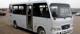
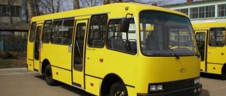
Surely everyone remembers the time when old LiAZs, LAZs and Ikaruses plied along the roads of cities and suburbs, carrying passengers in a variety of directions. However, they are not only outdated, but also completely do not meet modern safety and comfort requirements, which means that the vehicle fleet needs to be updated. MAZ buses are an alternative way out of the situation.
Thanks to modern developments, designers
created a whole range of MAZ buses, which today are in great demand due to their modern design, level of comfort and compliance with all passenger safety requirements. After the collapse of the Land of Soviets, the once eminent automobile manufacturer experienced very difficult times. Along with this, there was a need to completely renew the vehicle fleet that provided passenger transportation services. And in 1996, the first MAZ bus rolled off the assembly line, which became a replacement for the morally and technically outdated Ikarus.
The first model, although it met all the requirements, was far from ideal and was constantly improved over time. Along with it, new options were developed, which, thanks to their quality, gained trust and became widespread both at home and in the post-Soviet expanses.
Engine/powertrain characteristics
- Brand. Mercedes-Benz OM906LA.
- Type. Diesel.
- Number and arrangement of cylinders. 6 and in-line.
- Environmental safety standards. Euro-3.
- Working volume, l. 6,37.
- Engine power, kW (hp)/min. 279 (205) at 2200 rpm.
- Maximum torque, Nm/min. 1100 at 1200-1600 rpm.
- Engine location. Front.
- Checkpoint. Voith Diwa D851.3E, automatic hydraulic transmission, 3-speed, with hydrodynamic brake retarder
- Front-rear axle suspension. Dependent, pneumatic, two-cylinder with two body position regulators - Dependent, pneumatic, four-cylinder with two body position regulators.
- Control fuel consumption at 60 km/h, l/100 km. 28-30.
- Maximum speed, km/h. 75.
- Acceleration time to 60 km/h at nominal load, s. No more than 50.
- Pre-heating. Present.
Modifications[ | ]
List of modifications
| Name | Purpose | Gearbox type | Gearbox model | Engine model | Ecostandard | Years of manufacture | Note |
| MAZ-105.000 | urban | mechanical | Prague 5PS | MMZ-D260.5 | Euro-0 | 1997 | One copy |
| MAZ-105.040 | urban | mechanical | ZF 6S-85 | Renault MIDR 06.20.45 | Euro 1 | 1999 | |
| MAZ-105.041 | urban | mechanical | Prague 5PS | Renault MIDR 06.20.45 | Euro 1 | 2000 — 2004 | |
| MAZ-105.042 | urban | automatic | Voith D851.2 | Renault MIDR 06.20.45 | Euro 1 | 2000 — 2002 | |
| MAZ-105.060 | urban | automatic | Voith D851.3E | OM906LA | Euro 2 | 2001 — 2006 | |
| MAZ-105.065 | urban | automatic | Voith D851.3E | OM906LA | Euro-3 | 2006 — 2009 | |
| MAZ-105.465 | urban | automatic | Voith D851.3E | OM906LA | Euro-3 | 2008 — 2014 2017 | Restyling |
Equipment
- Independent liquid engine heater 30 kW Webasto, used for engine preheating and interior heating
- Independent air heater for driver's cabin 2.0-2.2 kW
- Anti-lock braking system ABS
- Traction control system ASR
- Radio equipment without radio: microphone, amplifier and 4 loudspeakers
- Tinted glass with valve windows
- Set of exterior mirrors, manufactured in the Republic of Belarus
- Driver's seat with air cushion, adjustable, manufactured by MAZ OJSC
- Thermal and noise insulating ceiling coating
- Anti-corrosion treatment of the bottom and hidden cavities
- Folding ramp for wheelchair access
- Equipment and mounting for one wheelchair
- Forced body tilt system Kniling
- Information system with interior display, manufactured in the Russian Federation or the Republic of Belarus
- Wear-resistant coating Grabiol
- Galvanized sheet on sides and roof
- Fog lights